Motor Laminations 101: Materials, Manufacturing, and How They Shape Motor Performance
Every design engineer runs into the same balancing act. You need higher motor efficiency without driving up cost. You want lower noise and heat yet you’ve got real packaging limits. If you’re weighing trade-offs between lamination materials, thickness, and processes while trying to hit performance and budget targets, you’re in the right place.
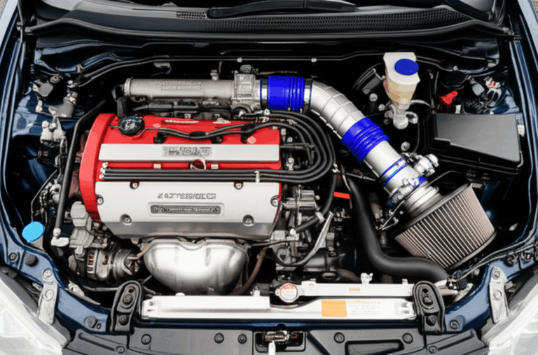
I’ll walk you through the fundamentals in plain language. You’ll see how lamination choices cut core loss and boost torque density. Then we’ll compare material and process options without bias, so you can pick the right path for your application. Finally, because many field failures get misdiagnosed as “bad laminations” when the real culprit is a motor capacitor, I’ve included a comprehensive appendix on how to check a motor capacitor with a multimeter. That way your team can separate magnetic core problems from power electronics issues with confidence.
In This Article
- Why Lamination Material Choice Is Critical
- Understanding Core Losses: Eddy Currents and Hysteresis
- Material Considerations for Motor Core Laminations
- Manufacturing and Assembly Processes That Matter
- Which Application Is This For? Selecting Best-Fit Solutions
- Quality, Tolerances, and Metrology: What Procurement Should Demand
- Troubleshooting Performance: Laminations vs. Capacitor Issues
- Appendix: How to Check a Motor Capacitor (A Step-by-Step DIY Guide)
- Engineering Takeaways and Next Steps
Why Lamination Material Choice Is Critical
The motor core quietly does the hard work. Laminations channel magnetic flux through the stator and rotor, set the torque constant, and shape efficiency. Good choices save watts and shed heat. Poor choices burn watts and cook windings.
- Thinner laminations reduce eddy current loss which helps at higher frequencies or with VFDs.
- Better steel grades lower hysteresis loss which lifts efficiency and keeps temperatures in check.
- Correct coatings prevent interlamination shorts which protects the stacking factor and cuts stray core loss.
- Clean punching processes reduce burrs which keeps insulation intact and preserves performance.
A lamination stack turns electromagnetic intent into mechanical output. Think of it as the motor’s “magnetic plumbing.” If the pipes are smooth and the valves are efficient, the flow does what you want with little waste.
Understanding Core Losses: Eddy Currents and Hysteresis
Let’s break this down simply.
- Eddy currents: Picture a river with little whirlpools. A changing magnetic field induces circulating currents in conductive steel that behave like those whirlpools. They waste energy as heat. Thinner, insulated laminations break up those loops into smaller, weaker swirls which cuts loss.
- Hysteresis: The material’s magnetic domains resist flipping with each AC cycle. That resistance creates loss. Steels with lower coercivity (resistance to demagnetization) reduce this. The B-H curve describes how flux density relates to magnetizing force. A slimmer loop means lower hysteresis loss.
Important levers you control:
- Lamination thickness: 0.50 mm, 0.35 mm, 0.27 mm, even 0.20 mm for higher frequency operation.
- Electrical steel grade: Higher silicon content or cobalt alloys lower loss and raise saturation.
- Coating class: Organic or inorganic coatings provide surface insulation and impact stacking factor.
- Flux density and frequency: The higher the flux swing and frequency, the more losses spike.
Rules of thumb help:
- Eddy current loss scales roughly with thickness squared and frequency squared.
- Hysteresis loss scales roughly with frequency and the area of the hysteresis loop.
In inverter-driven motors the effective electrical spectrum includes harmonics. You may design for 50/60 Hz yet your VFD introduces higher frequency components. Thinner laminations and higher grade steels help you mitigate those harmonics.
Relevant standards you can lean on:
- IEC 60404 for magnetic property measurements.
- ASTM A677 for non-oriented electrical steel sheet and strip.
- ASTM A683 for oriented electrical steel.
- IEEE Std 112 Method B for motor efficiency testing.
- NEMA MG 1 for design classification and performance.
Material Considerations for Motor Core Laminations
You have several families of materials. Each brings a different balance of saturation flux density, core loss, and cost.
- Non-oriented Silicon Steel (NOES, M-grades)
- Use cases: General purpose motors, compressors, pumps, fans, appliances.
- Pros: Good balance of cost and performance, available in common thicknesses, predictable behavior at 50/60 Hz and moderate inverter duty.
- Cons: Higher losses than premium grades at high frequency, saturation around 1.5–2.0 T depending on composition.
- Examples: M19, M27, M36, M45. Lower M numbers generally indicate lower loss grades.
- Grain-Oriented Silicon Steel (GOES, CRGO)
- Use cases: Transformers where flux prefers one direction.
- Pros: Very low loss in rolling direction for transformer cores.
- Cons: Not ideal for rotating machines since flux rotates. You lose the directional advantage inside stator and rotor laminations.
- High Silicon NOES and Low Loss Grades
- Use cases: High efficiency motors, higher speed or VFD applications.
- Pros: Lower hysteresis and eddy current losses, better performance at elevated frequencies.
- Cons: Higher cost, sometimes more brittle for processing.
- Cobalt-Iron Alloys (e.g., 49–50% Co)
- Use cases: Aerospace, high power density, high temperature, and very high speed machines.
- Pros: High saturation flux density which allows more torque or smaller cores, good mechanical strength, low loss at moderate frequency.
- Cons: Expensive, more demanding to process, may need specialized heat treatments.
- Soft Magnetic Composites (SMC)
- Use cases: Complex 3D flux paths, certain BLDC and axial flux machines.
- Pros: Isotropic magnetic properties, low eddy current loss due to insulating binder, enables shapes not possible with sheet laminations.
- Cons: Lower saturation than steel, different mechanical properties, design and manufacturing learning curve.
- Amorphous Metals
- Use cases: High frequency transformers and specialty machines.
- Pros: Very low core loss at high frequency.
- Cons: Cost, handling complexity, limited availability for traditional motor geometries.
If you need a deeper catalog overview with visuals and parameters, explore options like electrical steel laminations to see how grades, thicknesses, and coatings stack up.
What thickness should you pick
- 0.50 mm (0.020 in): Robust and cost-effective for 50/60 Hz induction motors with moderate VFD duty.
- 0.35 mm (0.014 in): Popular for higher efficiency builds and VFD-driven equipment.
- 0.27–0.20 mm: Useful when switching losses climb due to high carrier frequencies or when you push speed envelopes.
As frequency or harmonic content climbs you shift to thinner laminations to keep eddy currents in check. You also move to lower loss grades to cut hysteresis without starving torque.
Manufacturing and Assembly Processes That Matter
Material is half the story. How you cut, stack, and join laminations can make or break performance.
- Cutting methods
- Progressive die stamping: Best for volume. Low cost per part. Requires tight tool control, burr minimization, and stable lubrication. Watch die wear which increases burr height and can short laminations.
- Laser cutting: Excellent for prototypes and small runs. No tooling lead time. Heat-affected zone can alter local magnetic properties which pushes you to post-process annealing for the best results.
- Wire EDM: High precision with minimal burrs. Slower and costlier. Useful for critical features and trials.
- Burr control and edge quality
- Keep burrs below insulation thickness. Excess burrs puncture coatings and create interlamination shorts which drive up core loss.
- Deburring or light brushing helps. Do not remove too much material or smear coatings.
- Insulation coatings
- Inorganic and organic coatings provide surface resistivity. They impact stacking factor and lamination adhesion.
- Choose a coating that tolerates your bonding or welding process and your operating temperature.
- UL recognized coatings can simplify system approvals.
- Stacking and joining
- Interlocking: Tabs and notches snap laminations together like LEGO bricks which eliminates welding heat input and simplifies assembly.
- Bonding: Adhesive bonding creates a solid core with high rigidity and low noise. It improves heat transfer and reduces vibration.
- Riveting or cleating: Simple mechanical methods that suit some geometries and volumes.
- Welding: Use cautiously. Local heat degrades magnetic properties. When needed, control heat input and position welds away from high flux regions.
- Heat treatment and annealing
- Laser cut or heavily stamped parts may benefit from stress relief. Annealing restores magnetic performance by reducing residual stresses that widen the hysteresis loop.
- Follow supplier recommendations for time and temperature. Avoid decarburization or oxidation that hurts surface insulation.
- Rotor manufacturing
- Induction rotors: Die-cast aluminum is common and cost effective. Copper die-cast rotors offer lower rotor resistance for higher efficiency yet need specialized casting.
- Skew and bar design: Skew reduces cogging and noise. Bar geometry impacts starting torque and efficiency trade-offs.
You can dive deeper into specific subassemblies here:
- Stator design choices impact slot fill, losses, and cooling. See stator core lamination.
- Rotor geometry changes torque ripple and starting performance. Explore rotor core lamination.
- If you want the overall lamination stack perspective across motor types, visit motor core laminations.
Which Application Is This For? Selecting Best-Fit Solutions
Context shapes the right answer. Use the decision cues below to narrow your options.
- 50/60 Hz induction motors on across-the-line starters
- Material: NOES such as M27 or M36 with 0.35–0.50 mm thickness.
- Process: Progressive die stamping with tight burr control, interlocking or bonding stack.
- Notes: Focus on cost, quality control, and heat rise. Avoid over-spec that does not move the efficiency needle in your duty cycle.
- VFD-driven industrial motors with high switching frequencies
- Material: Lower loss NOES with 0.27–0.35 mm laminations. Consider premium silicon content grades for reduced hysteresis.
- Process: Bonding to improve damping and minimize audible noise driven by PWM ripple. Skew strategies for torque ripple.
- Notes: Harmonics push eddy losses up. Thinner laminations pay off here.
- High speed compressors or aerospace actuators
- Material: Cobalt-iron alloys for higher saturation which shrinks stack height or lifts torque density.
- Process: Precision cutting, post-cut annealing, and high-integrity bonding. Close control of tolerances and balance.
- Notes: Cost rises yet so do power density and thermal margins.
- BLDC and PMSM motors for appliances and e-mobility
- Material: Low loss NOES in thin gauges for higher electrical frequencies. SMCs in select 3D flux designs.
- Process: Segmental stators for automated needle winding. Adhesive bonding to boost rigidity and reduce acoustic noise.
- Notes: Consider ripple current in the DC bus and magnet temperature limits.
- Prototyping and complex geometries
- Material: Start with accessible low loss NOES for quick learning cycles.
- Process: Laser cutting and bonding let you iterate fast. Plan for a change to progressive die when you scale.
- Notes: Be honest about your volumes. Stamping shines at scale. Laser shines when the ink is not yet dry.
Here is a simple truth. Laser cutting offers precision and speed for early design. It scales poorly on cost. Progressive stamping asks for upfront tooling. It rewards you tenfold when you go to volume with consistent quality and tight cost control.
Quality, Tolerances, and Metrology: What Procurement Should Demand
What you buy should match what engineering specified. Align your quality language with recognized standards and measurable metrics.
- Material certifications
- Chemical composition and mechanical properties per ASTM or EN specifications.
- Magnetic property data per IEC 60404 including core loss at specified B and frequency.
- Coating callouts
- Coating class and thickness. Surface resistivity targets if applicable.
- UL or equivalent recognition if you want to streamline system approvals.
- Dimensional tolerances
- Critical features for slot geometry, OD/ID concentricity, and tab positions.
- Burr height limits relative to insulation thickness.
- Stack quality
- Stacking factor targets and measurement method.
- Bond line integrity or interlock pull tests. Vibration and noise assessments when relevant.
- Process controls
- Tool wear tracking and preventive maintenance.
- Annealing records and atmosphere control if used.
- Lot traceability with MTRs and PPAP level suited to your industry.
- Verification testing
- Epstein frame or SST measurements on sample material.
- Core loss testing on finished stacks if your application is sensitive.
- Motor efficiency validation per IEEE Std 112 Method B.
Procurement wins when suppliers show consistency, not just catalog promises. Ask for sample data that reflects your specific B and frequency conditions. That prevents surprises when the first production run lands on your dyno.
Troubleshooting Performance: Laminations vs. Capacitor Issues
Field issues often arrive as vague symptoms. The fan is weak. The compressor hums. The motor runs hot. Teams replace laminations or the entire motor when the real issue is a failing motor capacitor. A clear split-view helps.
When a lamination problem is likely:
- Elevated no-load current or temperature that does not trace to winding resistance or mechanical load suggests excessive core loss. Possible causes include poor grade substitution, interlamination shorts from burrs, or damage from welding heat.
- Audible noise and vibration that increases after a change in stacking or bonding can indicate poor stack integrity.
- Efficiency drop across the entire operating range that holds even after capacitor or inverter checks.
When a capacitor problem is likely:
- The motor hums but will not start on single-phase systems. A bad start capacitor or run capacitor is a common culprit in HVAC systems, well pumps, washing machines, and refrigerator compressors.
- Intermittent motor operation, slow start, or overheating with otherwise healthy mechanical components points to weak capacitance.
- Visual signs on the capacitor like bulging or leaking oil.
If your search led you here because you typed “motor hums but won’t start,” you probably need to test your motor capacitor. The appendix below gives you a complete, step-by-step guide that covers HVAC capacitor test methods, AC unit capacitor checks, fan motor capacitor checks, and more. It walks through multimeter capacitor functions, capacitance meter use, and safe discharge methods with clear cautions on electrical shock hazards.
This distinction saves time and money. Replacing a faulty capacitor might cost $10 to $50. Replacing a motor because of a misdiagnosis can cost hundreds or thousands.
Appendix: How to Check a Motor Capacitor (A Step-by-Step DIY Guide)
This section equips engineers, product designers, facility techs, and advanced DIYers to run a safe and accurate capacitor health check. You can use it for air conditioner capacitor testing, furnace capacitor tests, well pump capacitor tests, washing machine capacitor tests, and refrigerator compressor capacitor checks.
Introduction: Why Your Motor Capacitor Is Critical for Appliance Health
Motor capacitors boost starting torque and improve running efficiency in single-phase motors such as PSC motors (Permanent Split Capacitor) and CSIR or CSCR motors. A failing start capacitor or run capacitor can cause humming motors, slow starts, intermittent operation, overheating, and weak fans. Before you replace a motor or suspect laminations, run an accurate capacitor microfarad test and interpret the readings against the desired microfarad rating.
Safety First: Essential Precautions Before Testing
- Disconnect power at the circuit breaker or power supply. Verify with a non-contact voltage tester.
- Wear safety glasses and electrical gloves. Treat every capacitor like it is charged.
- Understand the electrical shock hazard. Capacitors can store a dangerous charge even when the AC voltage is off.
Tools You’ll Need for an Accurate Test
- Digital multimeter with capacitance (µF) function. A dedicated capacitance meter works too.
- Insulated screwdriver or a dedicated capacitor discharge tool with a resistor.
- Needle-nose pliers, marker, and paper for wiring notes and readings.
- Optional: ESR meter if you want to measure equivalent series resistance and ripple current behavior in detail.
Step-by-Step Guide: How to Safely Test a Motor Capacitor
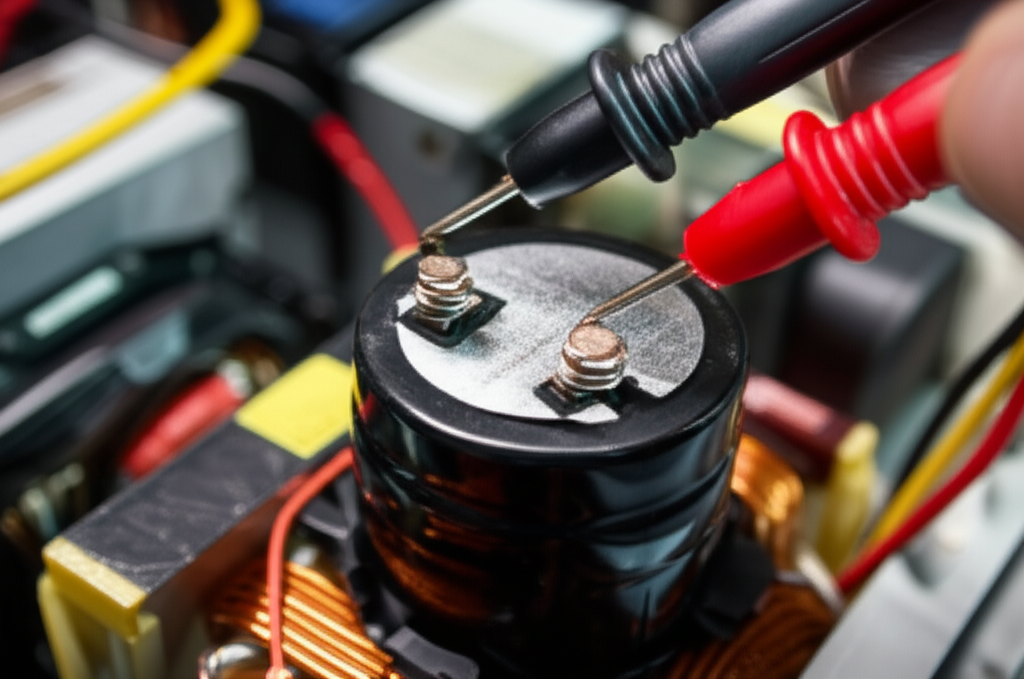
Step 1: Locate and Safely Access the Capacitor
Find the capacitor in your HVAC system, AC unit, blower motor, compressor compartment, or appliance motor housing. You’ll see start capacitors, run capacitors, and dual run capacitors in HVAC units labeled with “C,” “HERM,” and “FAN” terminals. Take a photo of wiring and refer to the wiring diagram before disconnecting anything.
Step 2: Discharge the Capacitor
- Method A: Insulated screwdriver
- Touch the metal shaft across the terminals to short them briefly. Expect a spark. For dual run capacitors, discharge each pair that includes the common terminal to HERM and FAN.
- Method B: Resistor discharge tool
- Use a high-wattage resistor with alligator clips to discharge more gently. This is safer for both you and the capacitor.
- Verification
- Set the multimeter to DC voltage. Confirm the residual voltage is near zero. Below 50 V DC is generally safe to handle. Aim for 0 V.
Step 3: Remove the Capacitor From the Motor Circuit
Carefully disconnect wires from the terminals with insulated pliers. Do not bend terminals. Note terminal labels and wire colors to avoid miswiring later.
Step 4: Perform a Visual Inspection
Look for:
- Bulging or dome-shaped tops and bottoms.
- Leaking oil or fluid.
- Burn marks, discoloration, melting, or corroded terminals.
Any physical damage means replace it even if it passes a capacitance test.
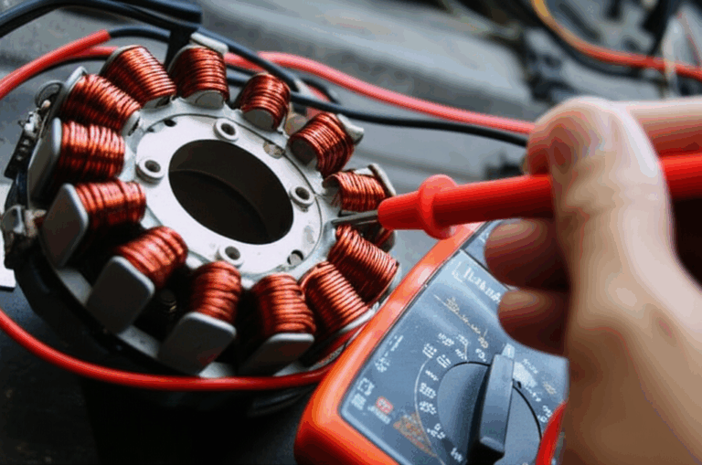
Step 5: Test Capacitance With a Multimeter
- Multimeter setup: Set to capacitance (µF or nF). Use auto-ranging or select a range higher than the printed microfarad rating.
- Connecting probes: Polarity is not a concern for AC motor capacitors. Place one probe on each terminal.
- Reading interpretation:
- Compare the reading to the printed label. Example: A dual run capacitor might read “35/5 µF.”
- Account for tolerance. Many motor capacitors list ±5% or ±10%. A 35 µF capacitor at ±5% should read between 33.25 and 36.75 µF.
- Good reading: Within tolerance.
- Bad reading: Significantly lower than stated, zero (open circuit), or “OL” on the meter indicating an open circuit.
Optional Step 6: Test for Short Circuit or Continuity With an Ohmmeter
- Set the multimeter to Ohms.
- Connect probes to terminals.
- A good capacitor may show a brief low resistance then rise to “OL” as the meter’s battery charges the dielectric.
- A continuous low resistance or zero indicates an internal short circuit.
Understanding Your Test Results: Good, Weak, or Failed
- Within tolerance: The capacitor is likely good. Look for other causes such as a seized bearing, high friction, wrong wiring on terminals, or an issue upstream.
- Significantly lower µF: The capacitor is weak and the motor draws higher current with reduced torque. Replace it.
- Zero µF or “OL”: The capacitor is open and cannot support starting torque. Replace it.
- Short circuit: Replace immediately.
- Physical damage: Replace on sight.
What to Do if Your Capacitor Is Bad (Replacement Guide)
- Match the µF value exactly for start capacitors and run capacitors.
- Match or exceed the VAC voltage rating. Do not pick a lower voltage rating.
- Match dimensions if space is tight. Consider dual run capacitors in HVAC systems where one can serve both blower motor and compressor.
- Confirm non-polarized types for AC motors. Polarity does not apply to these motor capacitors.
- Installation tips: Clean terminals, ensure tight connections, and secure the capacitor to prevent vibration-related failures.
- When to call a professional: If wiring is complex or you still have issues after replacement.
Application Notes for Common Use Cases
- HVAC capacitor test and AC unit capacitor check
- Dual run capacitors labeled “C,” “HERM,” and “FAN” support the compressor and fan motor. Incorrect wiring leads to immediate issues or blown fuses.
- Blower motor, fan motor capacitor check
- Symptoms include low airflow and overheating. A capacitor health check clears the doubt before you suspect a blower relay or contactor.
- Well pump capacitor test
- Humming and tripped breakers often point to start capacitor failure. Check both capacitor and control box components like the relay.
- Washing machine capacitor test
- Slow or no spin can be a failing capacitor or a motor winding issue. Use the ohmmeter to rule out an open or shorted winding if the capacitor checks out.
- Refrigerator compressor capacitor check
- Intermittent starting can be a weak run capacitor. If capacitance is within range yet issues persist, inspect the start relay.
Deeper Diagnostics for the Curious
- ESR test and ripple current
- An ESR meter tells you about internal losses. High ESR means more heat which shortens life. It is great for DC capacitors. For AC motor capacitors the µF reading plus visual inspection solves most cases.
- Temperature and environment
- High ambient temperature, frequent cycling, and voltage fluctuations accelerate capacitor degradation. For every 10°C rise above rating you roughly halve life.
Relevant Data, Case Studies, and Statistics
Quick Troubleshooting Tips and Terms You’ll See
- Bad capacitor symptoms include motor not starting, humming motor no start, intermittent motor operation, and reduced performance such as weak fan or slow wash cycle.
- Use a digital multimeter or analog multimeter for a quick capacitor check. Many DMMs have a dedicated multimeter capacitor function.
- You can perform a check capacitor with ohmmeter test to screen for shorts or opens when the meter lacks µF measurement.
- Understand capacitance units and tolerances. Farad vs microfarad matters. Most motor capacitors sit in the microfarad range with MFD reading accuracy driven by your meter’s spec.
- Watch for common capacitor failures like open capacitor test fails, shorted capacitor test fails, ground fault capacitor issues in control boxes, and leaky capacitor checks.
- Remember safety precautions and electrical safety guidelines. Use a capacitor discharge resistor when possible rather than only the screwdriver method.
- If the capacitor is out of specification replace it. A DIY capacitor check saves you from guessing and avoids replacing the entire electric motor or compressor.
Terminology and entities you’ll run into:
- Motor Capacitor, Start Capacitor, Run Capacitor, Dual Run Capacitor, Electrolytic Capacitor, Film Capacitor, Ceramic Capacitor.
- Multimeter, Capacitance Meter, Ohmmeter, Digital Multimeter, Analog Multimeter, ESR Meter.
- HVAC System, AC Unit, Compressor, Fan Motor, Blower Motor, Well Pump, Washing Machine, Refrigerator Compressor, Hermetic Compressor, PSC Motor, CSIR Motor, CSCR Motor.
- Microfarad (µF/MFD), Farad (F), Voltage (V), Ohm (Ω), Resistance, Capacitance, AC Voltage, DC Voltage.
- Circuit Breaker, Power Supply, Contactor, Relay, Wiring Diagram, Winding, Terminal, Capacitor Bank, Circuit Board.
- Safety Glasses, Insulated Screwdriver, Alligator Clips, Discharge Resistor, Insulated Pliers, Gloves.
If your capacitor checks out you may have other system issues such as a motor winding fault, an incorrect voltage rating capacitor, or a relay or contactor problem. If your system runs on a VFD you may also see symptoms tied to harmonics and not just the capacitor.
Engineering Takeaways and Next Steps
Here is the short list you can take to your next design review or supplier call.
- Focus on core losses first. Eddy currents shrink with thinner laminations and good insulation. Hysteresis falls with better grades and stress relief.
- Match your lamination thickness and grade to your frequency content. 50/60 Hz with no inverter duty calls for cost optimization. VFD-driven applications justify thinner gauges and premium grades.
- Control the process. Burrs, welding heat, and poor bonding can negate material advantages. Specify and verify burr height, coating class, stacking factor, and annealing when applicable.
- Choose manufacturing to fit your phase. Laser cut for development then stamp for scale. Be honest about volumes and timelines.
- Align quality with standards. Ask for IEC 60404 magnetic data and ASTM or EN material certifications. Validate with IEEE Std 112 motor testing where needed.
- Do not misdiagnose field failures. Many “motor” problems come from bad capacitors. Use the appendix to run a capacitance test before you blame the laminations.
If you want to benchmark materials and stack configurations quickly, review what’s commonly available for electrical steel laminations then compare how your application’s frequency and torque targets point to a specific path. For stator and rotor geometry discussions you can explore stator core lamination and rotor core lamination. For a broader overview of stack options and motor types you can consult motor core laminations.
When you are ready, bring a short brief to your supplier:
- Target speed and frequency content including VFD switching.
- Efficiency goal and thermal limits.
- Envelope constraints and weight targets.
- Expected volumes and manufacturing preferences.
With those inputs a good lamination partner can recommend a shortlist of materials and processes, estimate achievable loss and torque, and map a path from prototype to production. You reduce risk and hit your targets with fewer iterations.
Safe testing and smart design both start with clarity. You have it now.