Motor Laminations 101: A Practical Guide to Materials, Manufacturing, and Performance
Every design engineer faces the same challenge. You want higher motor efficiency without blowing the budget or the schedule. You also want to reduce heat, cut noise, and make assembly painless. The core of all those goals sits right in front of you. Motor laminations. Get the material and manufacturing right, and your motor runs cooler and lasts longer. Miss the details, and losses creep in while costs stack up.
This guide explains the fundamentals in clear terms. You will see how lamination thickness, material choice, and manufacturing methods shape efficiency, torque ripple, noise, and total cost. You will also get practical decision frameworks you can use today. Think of this as a conversation with a seasoned engineering partner who wants you to ship a great design.
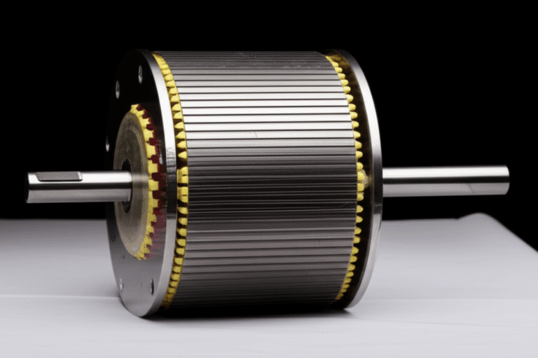
In case you are new to the topic, a quick definition helps. Motor laminations are thin sheets of electrical steel stacked to form the stator and rotor cores. The thin sheets reduce eddy currents by breaking up the conductive path. Coatings between the sheets provide electrical insulation. That is the simple picture. The details under the hood make or break performance.
In this Article
- Why Lamination Choice Is Critical to Efficiency, Heat, and Cost
- The Fundamentals: Core Losses and How Laminations Reduce Them
- Material Considerations: Steels, Alloys, Coatings, and Thickness
- Manufacturing and Assembly Processes: Pros, Cons, and Trade-offs
- Stator vs. Rotor Design Choices That Matter
- Tolerances, Burrs, Stacking Factor, and Quality Control
- Thermal and Mechanical Considerations in Real Motors
- Matching Solutions to Applications: Induction, PMSM, BLDC, EV, and More
- Cost, Procurement, and Supplier Collaboration
- Measurement and Verification: Proving Performance
- Common Pitfalls and How to Avoid Them
- Your Engineering Takeaway and Next Steps
Why Lamination Choice Is Critical to Efficiency, Heat, and Cost
You do not design laminations in a vacuum. You design them to hit your system goals. Efficiency. Torque density. Thermal limits. Acoustic targets. Cost. Schedule. The lamination stack sits at the center of all those constraints because it sets your magnetic circuit’s performance envelope.
- Efficiency ties directly to core losses. Those losses become heat. That heat drives insulation class choice, cooling strategy, and bearing life.
- Torque density depends on magnetic properties and saturation behavior. The B-H curve of your steel sets how much flux you can push before diminishing returns.
- Acoustic noise often traces back to magnetostriction in the steel and slotting choices that interact with the lamination geometry.
- Manufacturing choices ripple into performance. Burrs raise local losses. Heat-affected zones from cutting stiffen the B-H curve. Poor stacking pressure or inconsistent coatings raise eddy currents.
You want to pick materials and processes that meet your electrical frequency, flux density, and geometry needs. You also want to avoid over-speccing. The most expensive steel is not always the best fit. Sometimes a modest upgrade in thickness or coating beats a jump to a premium alloy. Sometimes a change in slot skew or stack bonding wins more than a material swap.
If you want a broad overview of lamination options and use cases, start with an overview of motor core laminations. It frames the range of choices you have.
The Fundamentals: Core Losses and How Laminations Reduce Them
At the heart of lamination design sits one idea. We want the magnetic circuit to carry flux efficiently while we starve unwanted currents that turn into heat.
Think in Whirlpools, Not Equations
Eddy currents act like small whirlpools in a river. The changing magnetic field induces circular currents inside the steel. Those currents waste energy as heat. Thinner, insulated laminations break up the big whirlpools into tiny ones. Smaller loops mean less heat.
Hysteresis loss is the price you pay each time the material’s magnetic domains flip direction as the field cycles. Imagine bending a paperclip back and forth. It warms up and work is lost on every bend. Magnetic domains do the same dance. Materials with lower coercivity waste less energy per cycle.
Engineers often use the Steinmetz model to estimate core losses as a function of frequency and flux density. You do not need the math here. The takeaway is simple. Loss rises with frequency. Loss rises with flux density. Different materials have different coefficients.
The Three Big Loss Buckets
- Eddy current loss: Dominates at higher frequencies. You control it with thinner laminations, better insulation coatings, and low-resistivity-path geometry.
- Hysteresis loss: Material dependent. Tied to coercivity and the shape of the B-H curve. Lower coercivity materials cut this loss.
- Excess or anomalous loss: Caused by domain wall motion and microstructural effects. This sits between the other two categories. Manufacturing stress and grain structure influence it.
How Thickness and Coating Help
- Thickness: Halve the thickness and you usually cut eddy current loss roughly by a factor of four for the same material and frequency. Real numbers vary but the trend holds. You can chase thinner gauges to fight eddy currents. You pay more per kilogram and you may see higher handling and tooling costs.
- Coating: Each lamination carries an insulating coating. The coating raises interlaminar resistance which starves those circulating currents. The coating also influences punching quality, weldability, and bonding.
Material Considerations: Steels, Alloys, Coatings, and Thickness
Electrical steels give you the best performance-to-cost ratio for most motors. They combine reasonable saturation, good resistivity, and reliable supply with standards that let you specify performance.
Non-Oriented Silicon Steel (CRNGO)
Use CRNGO when your motor sees rotating fields in all directions. The magnetic properties do not depend on a single rolling direction. That makes CRNGO ideal for induction motors and many PMSM/BLDC designs. You can source CRNGO in gauges like 0.50 mm, 0.35 mm, and down to 0.20 mm for higher-frequency work. As you thin the gauge you reduce eddy current losses and raise cost. You also improve stamping precision needs.
CRNGO grades vary by core loss at defined flux density and frequency. Standards like ASTM A677 and IEC 60404 define how to measure. Ask vendors for Epstein frame or single sheet test data at your target induction and frequency, not just catalog points.
If you want a quick refresher on the category see this overview of silicon steel laminations.
Grain-Oriented Silicon Steel (CRGO)
CRGO offers excellent performance along the rolling direction. Transformers love it because flux mostly travels in one direction around the core. Motors run rotating fields, so CRGO rarely helps. Some specialized axial-flux machines or unipolar sections can benefit from directional properties. Be cautious. If your flux path rotates, CRGO will not deliver its rated advantage.
High-Silicon Steels, Cobalt Alloys, and Nickel-Iron
- High-silicon electrical steels: More silicon increases resistivity and reduces losses. It also raises brittleness. That affects stamping and handling. You must plan for die wear and burr control.
- Cobalt-iron alloys (e.g., 49–50% Co): Cobalt offers high saturation induction and good high-frequency behavior. Use it when you push power density hard like in aerospace or high-speed machines. Price sits far above silicon steel. Evaluate system-level ROI before you jump.
- Nickel-iron alloys (Permalloys): These alloys excel at very low coercivity and high permeability at moderate inductions. They shine in sensors or low-loss applications at lower flux density. They cost more. Saturation sits lower than cobalt or silicon steel.
Coating Types and Why They Matter
Electrical steel comes with core plate coatings that control interlaminar resistance and surface behavior. ASTM A976 defines several coating classes. The most common types include:
- Inorganic coatings (e.g., C-2): Thin, heat resistant, good insulation. Suitable when you plan welding or high-temperature processes.
- Organic or semi-organic coatings (e.g., C-3 types): Higher insulation, good punchability, and bond with adhesives. Lower temperature resistance than fully inorganic classes.
- Phosphate-based coatings (e.g., C-5 types): Good insulation and punchability. Stable during stress-relief annealing.
Pick a coating that fits your manufacturing path. If you plan to laser cut and then stress-relief anneal, you need a coating that survives the heat. If you plan adhesive bonding, pick a coating that supports bond strength without squeeze-out that short-circuits layers.
Lamination Thickness: When to Go Thin
- 50/60 Hz industrial motors: 0.50 mm or 0.35 mm gauges handle most designs well. You can still spec 0.27 mm for premium efficiency.
- High-frequency or high-speed machines: Consider 0.27 mm down to 0.20 mm or thinner. As electrical frequency climbs, eddy current loss dominates. Thin gauges pay off.
- Prototype vs. production: In early feasibility work you can start with 0.35 mm to manage cost. Move thinner only if testing shows a clear win for your duty cycle.
Manufacturing and Assembly Processes: Pros, Cons, and Trade-offs
Great designs stumble when the manufacturing route undermines magnetic performance or blows up costs. Match the process to volume, geometry, and performance targets.
Stamping: The Workhorse for Volume
Progressive die stamping rules high-volume production. It offers excellent repeatability and low cost per part after you amortize the die. You will see tight dimensional control and good edge quality when the die and process are tuned.
- Pros: Best cost at scale. Strong dimensional repeatability. Compatible with interlocks and other stack features.
- Cons: Upfront tooling cost. Burrs if the die wears or the material is not optimized. Press tonnage and die stress increase with thin gauges.
Burrs matter. They create leakage paths between laminations which raise eddy currents. They can also cut the winding enamel. Specify max burr height. Inspect dies on a maintenance schedule. Account for burr orientation in stacking.
Laser Cutting, Waterjet, and Wire EDM: Precision and Flexibility
Laser cutting shines for prototyping and low-volume builds. You can iterate geometry without waiting on tooling. You can also resolve tight features. The trade-off is the heat-affected zone. The HAZ changes local microstructure and raises loss unless you stress-relief anneal.
- Laser cutting: Fast and flexible. HAZ on the cut edge requires mitigation for high-performance builds.
- Waterjet: No HAZ. Slower and can struggle with tiny features or edge taper.
- Wire EDM: Excellent precision and clean edges. Slowest of the three. Perfect for test coupons and small batches.
If you must laser cut for pilot runs then anneal before final stacking to recover losses. Use an inert or controlled atmosphere to protect the coating.
Assembly and Bonding: Interlocks, Welding, Rivets, or Adhesives
You have several ways to turn laminations into a rigid stack.
- Interlocking tabs: Think LEGO bricks. Tabs form during stamping and press together to lock sheets. You avoid adhesives or welding. You maintain insulation between layers. You also add local deformation which can raise local loss if overused.
- Welding: TIG or laser welds can provide high strength. The weld zone short-circuits laminations and adds HAZ. Use sparingly and away from peak flux paths.
- Rivets and cleats: Simple and reliable. They add assembly steps and may disturb local flux paths.
- Adhesive bonding or resin bonding: Excellent mechanical stability with minimal shorting. Can deliver very low vibration and noise. Requires clean surfaces and cure control.
Pick the method that fits your acoustic and mechanical targets. If you chase low noise you often end up with bonded stacks. If you need rugged mass production with minimal added steps you often prefer interlocks.
Stator vs. Rotor Design Choices That Matter
Stator and rotor cores face different constraints and failure modes. Design with those realities in mind.
- Stators: Slots and tooth geometry drive winding factors and thermal behavior. Slot fill, wedge choice, and insulation class define current density. End turns add copper loss. Skew helps reduce cogging and torque ripple. You want tight stack tolerances to maintain air-gap concentricity.
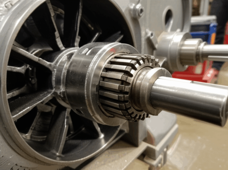
- Rotors: Rotor laminations carry slotting that interacts with the stator field. Skew can help reduce slot harmonics and acoustic noise. Rotor balance and mechanical integrity matter at speed. Shorting between laminations raises rotor heating fast.
For a deeper look at stator geometry and its implications see stator core lamination. If you are tuning rotor features, including skew and slot geometry, this overview of rotor core lamination helps frame the trade-offs.
Tolerances, Burrs, Stacking Factor, and Quality Control
Great drawings save programs. Define what matters and verify it consistently.
- Stacking factor: This is the ratio of effective steel height to the overall stack height. Coatings and micro-gaps reduce the factor. A stacking factor of 0.95 means 95% steel and 5% insulation/voids in height. It directly affects slot geometry and magnetic path length. Specify the target stacking factor and measure it on real stacks.
- Burr control: Call out maximum burr height and preferred burr direction. Ask for inspection at stake points in the die life. A small burr can undo a lot of good material choices if it bridges layers.
- Slot dimensions and position: Tolerances on slot width, tooth width, and slot pitch directly affect winding and torque ripple. Specify roundness and runout for the bore and OD to control air-gap quality.
- Insulation continuity: Test interlaminar resistance. Look for shorts across stacks, especially near interlocks, welds, or rivets.
- After-cut stress relief: If you laser cut or EDM material then consider stress-relief annealing. It recovers magnetic properties by relaxing stresses. Protect surface coatings during the heat cycle.
Standards like ISO 286 for fits, IEC 60034 for rotating machines, and IATF 16949 for automotive quality systems anchor your spec. Ask for material certs and core loss test data per IEC 60404 methods.
Thermal and Mechanical Considerations in Real Motors
Losses turn into heat. Heat raises winding resistance which increases copper loss and raises junction temperatures in power electronics. This feedback loop can eat your efficiency margins.
- Core loss distribution: Expect higher local losses at teeth and near slot openings. Those local hot spots drive insulation selection and slot liner design.
- Saturation behavior: Push B too high and hysteresis loss climbs while you lose effective inductance. You can also raise acoustic noise as the magnetostriction swings widen.
- Mechanical stresses: Press fits, shrink fits, and shaft assembly create stress. Stress shifts the B-H curve and raises loss. Limit press interference on the stator bore where the peak flux flows.
- Vibration and noise: Lamination choices and bonding methods matter. Soft bonding and full-surface adhesives can damp vibration. Interlock-only stacks may ring unless you add wedges or back iron damping.
- Speed and rotor dynamics: At high speeds the rotor stack end-face integrity matters. Adhesive bonding provides even load transfer. Rivets or welds concentrate stress.
A good thermal model includes core loss maps, not just a lumped number. Validate early using a stripped stator test with excitation that matches your real electrical frequency and induction levels.
Matching Solutions to Applications: Induction, PMSM, BLDC, EV, and More
No single stack fits all. Match the material and process to your application.
- 50/60 Hz industrial induction motors: CRNGO at 0.50 mm or 0.35 mm gauges hits IE2–IE3 level performance well. Go 0.27 mm to push IE4–IE5 with better steel and optimized slots. Progressive die stamping with interlocks gives good cost and performance.
- High-speed spindles and aerospace: Thin gauge CRNGO or cobalt alloys can pay for themselves in loss savings and weight. Favor adhesive bonding for low noise and mechanical stability. Laser-cut prototypes with anneal then migrate to stamping for volume.
- EV traction motors (PMSM/IPM): Electrical frequency rises with speed. Eddy currents become a headache in both stator and rotor. Use thinner gauges like 0.27 mm. Consider segmenting the rotor to reduce eddy currents in bridges and magnets. Choose bonding to control NVH and enable skewed stacks.
- BLDC and concentrated windings: Tooth tips see high local flux. Thin gauges and high-quality coatings reduce local heating. Skew or fractional-slot designs can suppress torque ripple. If you are designing a BLDC prototype or low-volume product, review this focused overview of bldc stator core.
Transformers operate at different duty and field orientation which is why they often use grain-oriented steels. If you also source transformer parts, this difference matters. Motors want non-oriented behavior. Transformers want directional performance and minimal magnetostriction.
Cost, Procurement, and Supplier Collaboration
You care about total cost, not just unit price.
- Tooling and amortization: Progressive dies cost money up front. They save you on part cost as volume climbs. Work with suppliers on break-even analysis between laser cutting and stamping.
- Material yield and scrap: Lamination blanks can waste material if the layout is not optimized. Ask for nesting studies. Minor geometry tweaks can lift yield.
- Coating compatibility and bonding: Adhesives and coatings must play well. Ask for bond strength and insulation resistance data on the exact coating.
- Quality systems and documentation: Look for suppliers with IATF 16949 or ISO 9001 and experience with PPAP. Ask for core loss certs at your target B and frequency per IEC 60404 or ASTM A343 methods.
- Logistics and rust prevention: Coated electrical steel resists rust better than bare steel but still needs protection. Specify packaging. Control humidity. Store indoors.
Procurement works best when engineering and suppliers speak the same language. Share your duty cycle, target flux density, and acoustic goals. Suppliers can recommend a coating or a stacking method that saves you iterations.
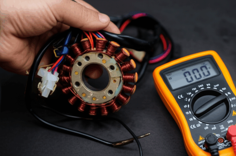
Measurement and Verification: Proving Performance
Trust but verify. Measure core loss and magnetic properties on samples and production parts.
- Single Sheet Tester (SST) and Epstein frame: Standardized methods to measure core loss and permeability at defined B and frequency. IEC 60404-2 covers the Epstein method. Ask for data near your operating points.
- Ring test or toroidal cores: Useful for quick checks but geometry differs from real teeth and slots.
- Stator core test: Drive the stator with a dedicated yoke and excitation to measure core loss at realistic flux distribution. Map temperature rise with IR imaging to locate hot spots.
- B-H loop measurements: Useful to confirm coercivity and saturation behavior. You can spot stress-induced changes after cutting or pressing.
Use the same test method across development to make apples-to-apples comparisons. Document the excitation waveform. Harmonics inflate losses, especially at higher flux densities.
Common Pitfalls and How to Avoid Them
- Picking CRGO for a rotating field: Grain-oriented steel underperforms when the field rotates. Choose non-oriented for motors.
- Ignoring coating choice: A great steel with the wrong coating can increase shorting and noise. Specify the coating early.
- Overlooking heat-affected zones: Laser-cut edges carry higher loss unless you anneal. Do not skip stress relief when performance matters.
- Under-specifying burrs: Burrs short laminations and can nick windings. Set a burr limit and check it often.
- Forgetting stacking factor: This drives geometric accuracy and magnetic path length. Include it in your design calculations.
- Over-saturating to chase torque: High B may give small torque gains with big loss penalties. Validate at real operating points.
- Not planning skew or slot geometry for NVH: Cogging and slot harmonics can spoil a great efficiency story. Small geometric tweaks can fix them.
Engineering Examples and Simple Rules of Thumb
- At 50/60 Hz, moving from 0.50 mm to 0.35 mm laminations often yields a noticeable drop in eddy current loss without a massive cost penalty. You also get better slot accuracy due to thinner stock.
- If your electrical frequency exceeds 1 kHz (common in high-speed machines), consider 0.27 mm or thinner gauges. Then watch the process window on stamping and annealing.
- Adhesive-bonded stacks reduce vibration and noise. They also improve dimensional stability during machining. Expect slightly higher process complexity and cure time.
- If your prototype uses laser cut laminations, plan a stress-relief anneal. Verify the coating survives. Measure loss before and after anneal to quantify the recovery.
A Note on Stator and Rotor Procurement
When you source both stator and rotor cores from a single supplier you streamline stack-up tolerances and skew alignment. It also simplifies communication about slot geometry interactions. Many teams standardize on a supplier that can produce both stator core lamination and rotor core lamination to reduce risk and speed up PPAP.
References and Standards You Can Trust
- IEC 60034 series: Rotating electrical machines.
- IEC 60404 series: Magnetic materials. Measurement methods for core loss and magnetic properties.
- ASTM A677 and ASTM A343: Specifications and test methods for electrical steel and core loss.
- ASTM A976: Classification of electrical steel coatings.
- ISO 286: Geometrical product specifications for limits and fits.
- IATF 16949 and ISO 9001: Quality management standards for automotive and general manufacturing.
You do not need to memorize these. You do need to recognize them in supplier quotes and data sheets. Standards anchor conversations and keep comparisons fair.
Your Engineering Takeaway and Next Steps
Here is the short list you can pin to your monitor:
- Define your electrical frequency and target flux density first. Those two numbers drive most material and thickness choices.
- Use non-oriented silicon steel for rotating fields. Pick gauge based on frequency and efficiency goals.
- Match manufacturing to volume. Stamp for production. Laser cut or EDM for prototypes. Anneal as needed to recover properties.
- Specify coating, burr limits, stacking factor, and skew in your drawings. Those details protect performance.
- Bonding method changes NVH and mechanical behavior. Interlocks win on speed. Adhesives win on stability and noise.
- Validate with real measurements at your operating points. Ask for SST/Epstein data at your B and frequency.
If you want a compact overview you can share with your team, start with this introduction to motor core laminations. If you are weighing steel choices for cost and performance, this snapshot of silicon steel laminations helps put the trade-offs in context. For BLDC or PMSM designs that use concentrated windings and skewed teeth, review bldc stator core. Finally, align stator and rotor decisions early with stator core lamination and rotor core lamination, especially if you plan skew or advanced bonding.
You now have the core concepts. You know what to ask for and what to watch. The next step is simple. Define your electrical frequency and flux density targets. Pick a gauge that makes sense. Choose a coating that fits your process. Then schedule a short technical consult with your lamination supplier to confirm the manufacturing route and tolerances. You will save yourself rework, and your motor will run cooler, quieter, and longer.