Motor Laminations 101: A Practical Guide for Engineers, Designers, and Procurement
Every motor designer faces the same hard trade-off. You want higher efficiency and lower heat. You also want repeatable manufacturing, sensible tooling costs, and on-time supply. If you’ve ever asked “How thin should my laminations be for this frequency?” or “Which steel grade gives me the best loss budget at my working flux density?” you’re in the right place.
In this guide, I’ll strip away jargon and give you the engineering fundamentals you need to make smart choices on motor laminations. We’ll walk through materials, thickness, manufacturing processes, and assembly methods. I’ll call out where each approach shines and where it bites. Then I’ll wrap with clear steps you can take to de-risk your next design and to have a sharper conversation with your lamination supplier.
Before we dive in, one quick promise. I’ll keep the math light and the explanations honest. If a topic has a caveat, I’ll spell it out. If an approach costs more for only marginal gains, I’ll say that too.
In This Article
- Why Lamination Choice Is Critical
- The Engineering Fundamentals: Core Losses and Magnetic Behavior
- Material Options for Motor Laminations
- Manufacturing and Assembly Processes: Trade-offs That Matter
- Matching the Right Solution to Your Application
- Design Details That Move the Needle
- Quality, Inspection, and Applicable Standards
- Cost, Lead Time, and Supply Risk
- Your Engineering Takeaway and Next Steps
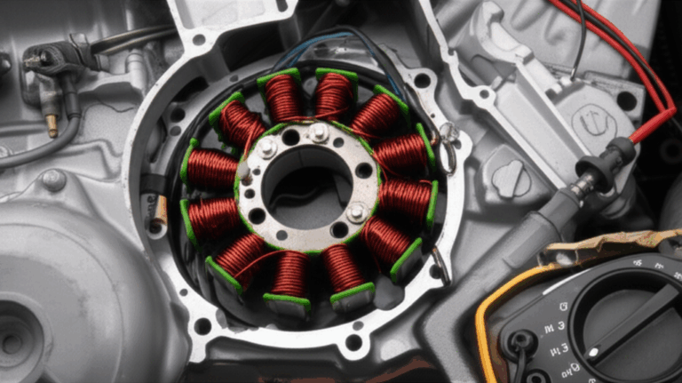
Why Lamination Choice Is Critical
Laminations are the backbone of your motor’s electromagnetic performance. They set the floor for core loss and the ceiling for power density. They influence noise and vibration. They even determine how forgiving your production line will be when you push speed or stack height.
Here’s the problem you’re solving:
- You must minimize core loss across your operating speed range.
- You must retain enough permeability to deliver torque without excessive magnetizing current.
- You must hold tight mechanical tolerances without pushing costs through the roof.
- You must choose a manufacturing route that scales from prototype to production without nasty surprises.
This isn’t theoretical. A mismatched steel grade or the wrong lamination thickness can swing efficiency by several points, which raises winding temperature and throttles output. Poor burr control can widen your airgap and spike acoustic noise. In short, the lamination stack can make or break your design.
If you need a quick orientation to the core elements before we dig deep, this primer on motor core laminations sets the stage.
The Engineering Fundamentals: Core Losses and Magnetic Behavior
Let’s unpack what’s really going on inside your steel. You have three main buckets of core loss. Think of them like three thieves that steal efficiency in different ways.
1) Eddy current loss
- Picture a river full of tiny whirlpools. Changing magnetic fields induce circular currents inside conductive steel. Those currents turn into heat. Thinner, insulated laminations chop large whirlpools into tiny eddies that waste far less energy.
- Eddy loss scales roughly with the square of both frequency and lamination thickness. Double the frequency and you quadruple this loss. Cut thickness in half and you quarter it, which is why high-frequency machines lean hard on 0.20–0.27 mm sheets.
2) Hysteresis loss
- This is the energy you pay to flip the material’s magnetic domains back and forth every cycle. It depends on the area of the B-H loop. Materials with lower coercivity (resistance to demagnetization) produce smaller loops and lower hysteresis loss.
- Hysteresis loss rises nearly linearly with frequency at a given peak flux density, which matters for high-speed motors even if you’ve already trimmed eddy currents with thin laminations.
3) Excess (or anomalous) loss
- Real materials have microstructure features, stress, and grain boundaries. These cause additional loss beyond the tidy eddy plus hysteresis model. Punching damage and coatings can nudge this up or down, which is why process control matters.
Key material properties that drive these losses and your torque:
- Magnetic permeability: How easily flux lines pass through the material. High permeability helps you achieve target flux at lower magnetizing current. Think of permeability like the sponge’s thirst for water. Thirsty sponge, easy flux.
- Saturation flux density (Bs): The top end of how much flux the material can carry. Higher Bs lets you push power density in iron-dense designs before you hit the wall.
- Coercivity (Hc): The material’s resistance to changing magnetization. Lower Hc usually means lower hysteresis loss.
- Electrical resistivity: Higher resistivity reduces eddy currents. Silicon raises resistivity in iron. So does temperature to a point.
A quick word on frequency. The electrical frequency that matters to the steel equals pole pairs times mechanical rotational speed. A 10-pole machine at 8,000 rpm sees 667 Hz electrical. That’s why small, high-speed BLDC and traction motors often need 0.20–0.35 mm laminations even if they never touch the grid at 50/60 Hz.
Stacking factor and interlamination insulation matter too:
- Stacking factor (fill factor): The ratio of steel to total stack height. Coatings, roughness, and burrs reduce this factor. Lower stacking factor means less iron per millimeter, so you may need more stack height to hit the same flux.
- Insulation coatings: Very thin inorganic or organic layers on each sheet raise interlamination resistance. This curbs eddy currents that try to sneak across layers. Coating class, cure, and pressure during stacking affect real-world loss.
Finally, stress is not your friend. Punching, laser heat affected zones, and welding all add mechanical stress. Stress raises loss and lowers permeability. This is why burr control, die maintenance, and post-process annealing (when suitable) can pay dividends.
Material Options for Motor Laminations
You’ve got a spectrum of choices. Pick the material that fits your frequency, flux density, temperature, and cost targets. No single alloy wins every category.
Non-Oriented Electrical Steel (NOES), Fe-Si (M-Grades)
The workhorse. Used in most rotating machines from fans to EV traction motors.
- Typical silicon content: ~2.0–3.2%. Silicon boosts resistivity and reduces hysteresis.
- Thickness options: Commonly 0.50 mm, 0.35 mm, 0.27 mm, and 0.20 mm.
- Grades: Often referenced as M19, M27, M36 etc, though modern standards differ by region. Lower numbers usually mean lower loss at a specified thickness.
- Strengths:
- Balanced loss and cost at medium flux densities.
- Broad supply base. Predictable performance. Good mechanical integrity for stamping.
- Watch-outs:
- Loss rises quickly at higher frequencies if you don’t thin the gauge.
- Residual stress from punching degrades loss more than datasheets imply. Tooling quality matters.
- Where it fits:
- General industrial motors at 50/60 Hz.
- Servo and traction motors in 200–800 Hz electrical ranges when using thinner gauges.
Learn more about the base material family here: electrical steel laminations.
Grain-Oriented Electrical Steel (GOES), CRGO
Optimized for unidirectional flux. It shines in transformers with steady, aligned magnetic paths.
- Strengths:
- Very low loss along the rolling direction at 50/60 Hz. Great for transformers and reactors.
- Watch-outs:
- Poor off-axis properties. Rotating machines move flux in multiple directions through teeth and yokes. GOES loses its edge and can underperform in motors.
- Where it fits:
- Power transformers and specialty directionally biased components. Not typical for motors.
Cobalt-Iron Alloys (Fe-Co)
The power density play. When you push flux density hard and want a higher saturation point, Fe-Co steps up.
- Saturation flux density: Up to ~2.35 T or more vs ~1.9–2.1 T for Fe-Si.
- Strengths:
- Higher Bs lets you run compact stator teeth and yokes at elevated flux density.
- Suitable for high-speed, high-power-density machines like aerospace or advanced traction.
- Watch-outs:
- Much more expensive than Fe-Si. Tooling wear can be higher. Annealing often required to restore magnetic properties after stamping.
- Thinner gauges help with eddy loss, which compounds cost.
- Where it fits:
- High-performance aerospace, turbo-machinery, and premium traction motors.
Nickel-Iron Alloys (Ni-Fe, Permalloy family)
The low-loss, high-permeability option at modest flux densities.
- Strengths:
- Exceptional permeability and low hysteresis loss in specific compositions.
- Watch-outs:
- Lower saturation flux density than Fe-Co or Fe-Si. Cost is significant. Mechanical robustness can limit stamping speed.
- Where it fits:
- Niche sensors, magnetic bearings, or low-flux-density machines. Less common in mainstream motors.
Amorphous and Nanocrystalline Alloys
Ultra-low loss at high frequency in transformers. Rotating machines sometimes trial them.
- Strengths:
- Very low eddy and hysteresis losses at high frequency due to unique microstructure.
- Watch-outs:
- Brittle. Challenging to stamp. Assembly can be complex. Expensive. Surface roughness and stacking factor can be unfavorable.
- Where it fits:
- Emerging high-frequency applications with very specialized designs. Not a drop-in for general motors.
Coating Systems and Insulation
The coating you choose affects interlamination resistance, stacking factor, bonding, and weldability.
- Inorganic phosphate or oxide coatings: Thin, robust, high interlam resistance. Common for stamped stacks with mechanical interlocks.
- Organic coatings and backlack: Thermosetting adhesives allow bonding during bake cycles. They create rigid stacks with excellent interlam resistance and low noise. Process control is critical.
- Standard practice:
- Select coating to match process. If you plan laser welding, choose a coating that tolerates it. If you plan bonding, pick a backlack compatible with your cure schedule.
- Reference ASTM A976 for coating classifications and properties.
If you need a quick material recap with practical context, this page on silicon steel laminations covers the essentials.
Manufacturing and Assembly Processes: Trade-offs That Matter
You have more than one way to get precise laminations into a tight stack. Each method trades speed, cost, edge quality, and magnetic damage differently.
Blanking and Cutting Methods
- Progressive die stamping
- Best for volume. Lowest cost per part at scale. High repeatability.
- Risks and controls: Burr height, die wear, and residual stress. Maintain sharp tools and tight die clearances. Target burr height well under 10% of sheet thickness for tight airgaps and smooth stacking.
- Design for manufacturability: Radii at stress risers, avoid thin webs that deform during blanking, and nest efficiently to reduce scrap.
- Compound die stamping
- Suited for medium volumes or complex profiles that benefit from single-hit tolerances.
- Similar risk profile to progressive with slower throughput.
- Laser cutting
- Ideal for prototypes and low-volume, rapidly iterated designs. No tooling cost. Complex shapes and quick design spins.
- Watch the heat affected zone (HAZ). HAZ introduces local stress and can raise loss. Use optimized parameters and post-process cleaning to reduce oxidation.
- Edge roughness is higher than stamping unless carefully tuned.
- Wire EDM
- Excellent precision and edge quality with minimal mechanical stress. Great for very fine features and R&D.
- Slow and costly for production volumes.
- Waterjet
- No HAZ. Flexible. Surface quality and taper can be a challenge. Slower than stamping. Less common for production stacks.
Stacking and Assembly Methods
- Loose stacking with through-bolts or bands
- Simple and serviceable. Some vibration and potential for interlam slippage.
- Lower assembly cost. Acceptable for larger machines and lower NVH demands.
- Interlocking (self-riveting features)
- Tabs formed during stamping snap laminations together. Think LEGO bricks for steel.
- No adhesives or welds. Good stack rigidity. Slightly lower stacking factor due to interlocks. Tooling must control tab geometry tightly.
- Adhesive bonding (backlack)
- Laminations stack, then bake to cure adhesive layers into a solid core. Excellent rigidity and NVH performance. High interlam resistance.
- Requires controlled press pressure and temperature profile. Rework is limited, so process discipline matters.
- Welding (stitch, laser, TIG)
- Adds strength in select locations. Useful for rotors with pockets or bridges that need reinforcement.
- Creates local HAZ and stress. Plan weld placement to minimize magnetic harm. Pre-qualify welding parameters.
- Riveting or cleating
- Mechanical fasteners that add stiffness without heat. Watch for local mechanical distortion or stack bulge.
Stator and rotor assembly can each benefit from different approaches. If you’re weighing options for the stator in particular, this overview on stator core lamination is a helpful primer. For rotors with bridges, magnet pockets, or skew, this resource on rotor core lamination covers the unique mechanical and magnetic constraints at play.
Matching the Right Solution to Your Application
Let’s get specific. Here’s how I’d frame the choice set by application type and operating conditions.
- 50/60 Hz industrial induction motors
- Material: NOES Fe-Si at 0.50 or 0.35 mm depending on size and efficiency target.
- Process: Progressive die stamping for volume. Interlock or bolt for stator stacks. Rotor skew by several slot pitches to reduce noise and torque ripple.
- Priority: Low loss at 50/60 Hz and robust mechanical strength.
- High-speed BLDC or PMSM (electrical 200–1,000+ Hz)
- Material: NOES Fe-Si in 0.35, 0.27, or 0.20 mm. Consider Fe-Co where flux density and power density justify cost.
- Process: Stamping with high-precision dies once the design freezes. Laser cutting for early prototypes. Adhesive bonding for NVH and rigidity in stators. Rotor bridges sized for burst speed with minimal flux choke.
- Priority: Eddy loss control through thin gauge and clean edges. Tight tolerances on tooth tips and airgap. Secure magnet retention.
- Traction motors for EV/HEV
- Material: Premium low-loss NOES at thin gauges. Fe-Co in niche, high power density designs.
- Process: High-volume stamping and bonding for stator. Rotor designs vary by interior vs surface PM, each with unique pocket and bridge requirements. Skew or fractional-slot windings to reduce cogging.
- Priority: Efficiency across a wide speed range. NVH control. Supply chain stability for steel and magnets.
- Aerospace and 400 Hz systems
- Material: Thin-gauge NOES or Fe-Co depending on flux density and envelope. Often 0.20–0.27 mm.
- Process: Precise stamping with post-process stress relief for Fe-Co. Bonded stator stacks favored for weight and NVH.
- Priority: Power density and thermal stability under strict safety standards.
- Specialty low-flux, high-sensitivity applications
- Material: Ni-Fe alloys in select sensor or magnetic bearing contexts.
- Process: EDM or carefully controlled stamping. Bonded stacks where rigidity and noise matter.
- Priority: Ultra-low hysteresis and high permeability.
If you’re working in BLDC or PMSM and need a focused perspective on stator-specific constraints, this BLDC-focused page on bldc stator core is a concise reference.
Design Details That Move the Needle
A handful of small decisions add up. This is where good designs separate from great ones.
- Lamination thickness vs frequency
- Rule of thumb:
- ≤100 Hz: 0.50–0.35 mm works in many cases.
- 100–400 Hz: 0.35–0.27 mm is a strong sweet spot.
- 400–1,000+ Hz: 0.27–0.20 mm earns its keep.
- Validate with your loss budget and flux density. Use vendor loss curves for your exact grade and thickness. Then add a margin for manufacturing stress.
- Flux density targets
- Running at 1.4–1.6 T in stator back iron is common for NOES. Teeth often run higher for short dwell times, but watch rising hysteresis and acoustic noise.
- Fe-Co allows higher peaks, which reduces copper mass and stack length. It might raise core losses if you don’t rein in thickness and stress.
- Tooth tip and slot geometry
- Tooth-tip radius and yoke relief shape your local flux. Small chamfers or notches can cut local saturation and reduce noise. Finite element analysis helps but always sanity-check with manufacturability in mind.
- Skew
- Skew reduces cogging and torque ripple. It also complicates stacking and can cut peak torque. Heavy skew makes rotor balancing harder. Use just enough to meet your ripple spec.
- Burr control and edge quality
- Burrs raise interlam contact points and reduce interlam resistance. They can widen the airgap if not removed or controlled. Use sharp tooling, proper die clearance, and de-burr as needed. Never let burrs face the airgap side.
- Stacking factor and pressure
- Higher stacking factor gives more iron per length, which helps flux. Excessive pressure during bonding can squeeze out adhesive and reduce interlam insulation. Find the sweet spot through controlled process trials.
- Rotor bridges and pocket geometry (for PM rotors)
- Bridges prevent magnet blowout at high speed but choke flux. Balance structural safety at burst speed with magnetic performance. Non-magnetic sleeves add another knob to turn for retention and NVH.
- Thermal path and coating selection
- Coatings influence heat flow between laminations. Adhesive layers add thermal resistance. That can be good for NVH and bad for heat extraction. Design your cooling with the actual stack-up in mind, not a textbook cross-section.
Quality, Inspection, and Applicable Standards
What you measure, you improve. Plan how you’ll verify that lamination performance on paper survives manufacturing.
- Incoming material verification
- Confirm thickness, coating class, and mechanical properties. Check heat numbers and certification.
- Sample magnetic loss and permeability data when critical. Vendor single-sheet test data should match your grade expectations.
- Dimensional control
- Use tight GD&T on key features: airgap critical edges, tooth tips, slot width, and stack height. Validate burr height routinely.
- Check skew angles and stack flatness after assembly.
- Magnetic property verification on stacks
- Single-sheet tests set a baseline. Full-stack tests catch real process effects. Epstein frame or single sheet testers define base properties per IEC 60404 series. Use representative laminations and real coatings when testing.
- If you bond or weld stacks, run before/after loss comparisons at a relevant induction and frequency.
- Coating and insulation checks
- Measure interlamination resistance and coat weight per ASTM A976 classification guidance. Confirm cure conditions for backlack adhesives and shear strength of the bonded stack.
- Applicable standards and references
- ASTM A677: Specifications for non-oriented electrical steel.
- ASTM A683: Specifications for grain-oriented electrical steel.
- ASTM A976: Classification of insulating coatings on electrical steels.
- IEC 60404 series: Methods for magnetic measurements, including loss and permeability.
- IEEE publications: Numerous papers on punching-induced stress, loss modeling, and material characterization in rotating machines.
Document your acceptance criteria in the control plan. Match inspection frequency to risk and to the stage of your ramp.
Cost, Lead Time, and Supply Risk
Great designs die in the real world if supply cannot keep up. Bake these realities into your plan.
- Tooling economics
- Progressive dies cost real money and time. They deliver the best cost per part at volume. Laser or EDM is your friend in prototyping and early pilot builds.
- Plan for a design-freeze milestone when you shift from laser to stamping. A small change after die build can cost more than the change is worth.
- Material availability
- Premium thin-gauge NOES and Fe-Co have longer lead times. EV demand can tighten supply. Qualify at least two grades or mills when possible.
- Keep a cross-grade mapping with impact on loss and saturation. This lets you pivot if a mill allocation moves.
- Scrap and yield
- Nested layout efficiency hits your cost. Complex geometries with lots of internal cutouts increase scrap percentage. Design with nesting in mind and ask your lamination partner for an optimization pass early.
- Process speed vs quality
- Stamping speed raises throughput and burr risk. Bonding cure time sets takt time for stack assembly. If you need volume, align cure cycles with line flow from the start.
- Compliance and sustainability
- Confirm RoHS and REACH status for coatings and adhesives. Cobalt content in Fe-Co raises cost volatility and ESG scrutiny. Keep stakeholders in the loop on material choices.
If you’re looking for a quick market-to-technology snapshot and a place to start a technical conversation with a supplier, this overview of motor core laminations is a practical jumping-off point.
Problem – Explain – Guide – Empower: A Quick Recap
- The problem
- You need to hit efficiency and power density targets without blowing up cost, lead time, or manufacturability. Lamination thickness, material grade, and assembly process decide that outcome.
- The explanation
- Core losses split into eddy, hysteresis, and excess components. Eddy loss loves thick laminations and high frequency. Hysteresis loss tracks frequency and coercivity. Stress and coatings swing real-world results.
- The guide
- Choose NOES Fe-Si for most motors and thin the gauge as frequency rises. Consider Fe-Co for high power density. Pick manufacturing methods to match volume, complexity, and NVH. Control burrs, stress, and stacking pressure. Verify performance with stack-level tests, not just datasheets.
- The empowerment
- Build a short, defensible spec: frequency range, target Bpk, allowable loss, lamination thickness, coating class, stacking method, and verification plan. Get quotes early for both laser-cut prototypes and progressive-die production. Ask for data at your operating induction and frequency, not just catalog test points.
Your Engineering Takeaway and Next Steps
Here are the high points you can act on today:
- Choose thickness to match frequency
- ≤100 Hz: 0.35–0.50 mm typically suffices.
- 100–400 Hz: 0.27–0.35 mm reduces eddy loss sharply.
- 400–1,000+ Hz: 0.20–0.27 mm deserves a hard look.
- Match material to your flux and budget
- NOES Fe-Si is the default for most motors. Use premium low-loss grades for efficiency programs. Consider Fe-Co when you need higher saturation and can justify the spend.
- Control the process, never just the print
- Sharp dies, low burrs, and minimal stress preserve magnetic properties. If you bond, optimize pressure and cure. If you weld, keep heat away from critical flux paths.
- Validate at the stack level
- Test loss at your operating induction and frequency before you lock the design. Verify interlam resistance and stacking factor on real parts.
- Plan for scale
- Prototype with laser or EDM. Transition to stamping once geometry stabilizes. Align adhesive cure cycles with your takt time. Qualify dual sources for critical materials.
If you want to fast-track your evaluation, share your target frequency range, peak induction, and envelope constraints with a lamination partner. Ask for a side-by-side on two gauges and two grades at your actual operating points. You’ll see the trade-offs in black and white.
And if you’re reviewing material choices or stack architectures, these resources will help you go deeper:
- Overview of electrical steel laminations
- Practical details on stator core lamination
- Mechanical and magnetic considerations for rotor core lamination
- Material pointers for silicon steel laminations
We’re happy to act as a sounding board. Bring us your frequency, Bpk, stack height, and NVH goals. We’ll help you narrow choices and derisk your path from prototype to production.
References and standards you can cite in internal reviews:
- ASTM A677: Non-Oriented Electrical Steel Specifications
- ASTM A683: Grain-Oriented Electrical Steel Specifications
- ASTM A976: Classification of Insulating Coatings on Electrical Steels
- IEC 60404 series: Magnetic Materials Measurement Methods
- Selected IEEE Transactions on Magnetics papers on punching-induced loss, single-sheet testing, and loss modeling in rotating machines
Final note. Don’t let perfect be the enemy of shipped. Start with a simple thickness and grade matrix. Run quick tests at your working induction and frequency. Then tighten the loop. That’s how high-efficiency motors get built on time and on budget.