Integrated Drive Units: Stator Packaging and Rotor Size Trade-offs
Every engineer working on electric vehicles, robotics, or advanced industrial automation faces a formidable challenge: squeezing more power out of a smaller, lighter package without breaking the bank or creating a thermal nightmare. If you’ve ever found yourself deep in CAD models, weighing the complex trade-offs between stator winding techniques and rotor geometry, you understand this delicate balancing act. You’re trying to design a system that’s not just powerful but also efficient, quiet, and reliable.
The heart of this challenge lies within the Integrated Drive Unit (IDU), a marvel of mechatronic design that combines the motor, power electronics, and gearbox into a single, compact housing. But this integration, while solving many problems, creates a new set of intricate engineering puzzles. The two most critical and interdependent of these are stator packaging and rotor sizing. How you wind the stator directly impacts the rotor’s potential and how you size the rotor dictates the stator’s design constraints.
Mastering this intricate relationship is no longer just an academic exercise; it’s the key to unlocking the next generation of high-performance electric drive systems. This guide will break down the fundamental principles, explore the critical trade-offs, and provide actionable insights to help you navigate these complex design decisions with confidence.
What We’ll Cover
- Understanding Integrated Drive Units (IDUs) in Context: A look at the components, benefits, and unique challenges of IDUs.
- The Critical Role of Stator Packaging in IDUs: How winding techniques, slot fill, and thermal design influence performance.
- Rotor Sizing: Diameter, Length, and Performance Parameters: Exploring the profound impact of the rotor’s shape and size.
- Navigating the Core Trade-offs in IDU Design: Balancing power density, efficiency, thermal management, NVH, and cost.
- Advanced Strategies and Future Trends in IDU Optimization: A glimpse into the future with new materials, simulation tools, and manufacturing methods.
Understanding Integrated Drive Units (IDUs) in Context
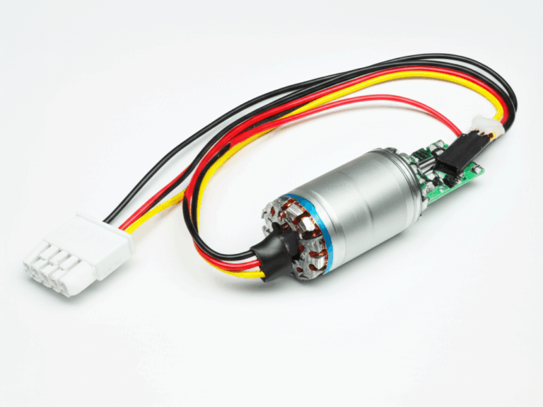
At its core, an Integrated Drive Unit, often called an e-axle in the automotive world, is a highly consolidated electric powertrain. Instead of having a separate motor, inverter (the electronic brain that converts DC battery power to AC for the motor), and gearbox connected by bulky high-voltage cables, an IDU brings them all together into one sleek, efficient package.
The primary advantages of this integration are compelling:
- Compactness & Power Density: By eliminating external connections and housings, IDUs achieve a much higher power density. This means more power in less space, a critical factor for everything from creating more passenger room in a BEV to designing a more agile robotic arm.
- Weight Reduction: Fewer housings, shorter cables, and integrated cooling loops lead to significant system weight reduction, which directly improves vehicle range or the payload capacity of a machine.
- Simplified Assembly: For an OEM, installing a single, pre-tested IDU is far simpler and faster on the assembly line than plumbing and connecting three separate components.
- Improved Efficiency and NVH: Shorter high-voltage paths between the inverter and motor reduce electromagnetic interference (EMI) and power losses. A single, rigid housing also allows for better management of noise, vibration, and harshness (NVH), resulting in a quieter, smoother operation.
However, this tight integration isn’t without its engineering headaches. When you pack heat-generating components—the motor’s copper windings and the inverter’s power switches—into a shared space, thermal management becomes exponentially more complex. A hotspot in one area can quickly affect the performance and reliability of another, creating a complex puzzle of multi-physics interactions that designers must solve.
The Critical Role of Stator Packaging in IDUs
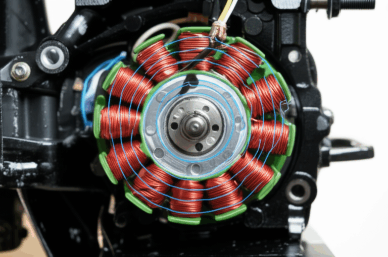
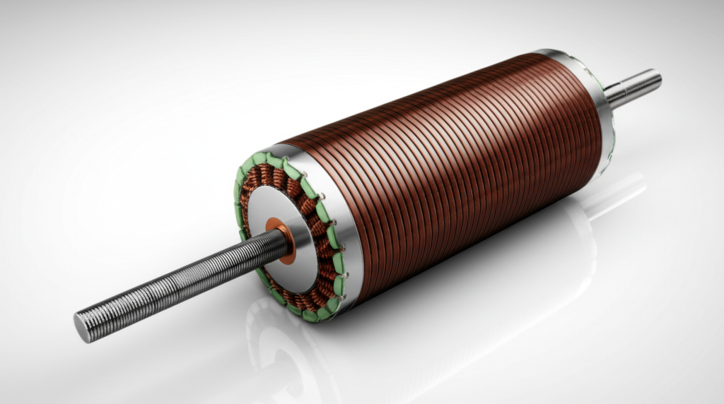
The stator is the stationary part of the electric motor, and its design is a masterclass in compromise. It’s essentially a laminated steel core with slots cut into it to hold copper windings. When electricity flows through these windings, it creates a rotating magnetic field that drives the rotor. How you “package” that copper into the stator is one of the most consequential decisions in IDU design.
Winding Topologies and Their Impact
The method used to insert copper into the stator slots dramatically affects performance. For years, random-wound windings—where round copper wires are essentially bundled and pushed into the slots—were the standard. This method is flexible but leaves significant air gaps, leading to a poor “slot fill factor.”
Enter hairpin windings. This technique uses pre-formed, rectangular copper conductors that look like hairpins. They are inserted into the slots and then bent and welded at the ends. The advantages are transformative for IDUs:
- Massively Improved Slot Fill Factor: Hairpin windings can boost the slot fill from a typical 40-55% for random-wound to over 70%. This is like upgrading from tossing clothes into a suitcase to neatly folding and rolling them—you fit far more in the same space.
- Higher Current Density: More copper means the motor can handle more current, which translates directly to higher torque output.
- Better Thermal Performance: The flat surfaces of the rectangular conductors provide a much larger contact area with the stator laminations, creating a more effective pathway for heat to escape.
While concentrated windings have their place, particularly in lower-speed, high-torque applications, the high power density demands of modern IDUs have made hairpin windings the go-to solution for major automotive OEMs.
Optimizing Slot Fill Factor for Power Density
Slot fill factor is a direct measure of how much of the available slot area is filled with conductive copper versus insulation and air. A higher slot fill allows you to push more current through the stator for a given size, increasing magnetic loading and generating more torque. As one industry benchmark shows, moving to an advanced winding technique like hairpin can yield a 15-20% increase in continuous torque density for the same motor volume.
This doesn’t come for free. Achieving a high slot fill requires extremely tight manufacturing tolerances, advanced insulation systems that are both thin and robust, and sophisticated impregnation techniques (using epoxy resins to fill remaining gaps) to ensure thermal conductivity and structural integrity.
Thermal Management within the Stator
The two primary heat sources in a motor are copper losses (I²R losses from current flowing through windings) and iron losses (from the changing magnetic field in the stator core lamination). In a densely packed stator, this heat has to go somewhere.
Modern IDUs employ sophisticated cooling strategies to manage this thermal load:
- Direct Oil Spray/Jet Cooling: High-velocity jets of oil are sprayed directly onto the end windings—the hottest part of the stator—to carry heat away efficiently.
- Integrated Water-Glycol Jackets: Channels are cast directly into the IDU housing, allowing a coolant mixture to circulate around the stator, drawing heat out.
- Potting Compounds: Thermally conductive epoxies are used to encapsulate the windings, eliminating air voids and creating a solid path for heat to transfer to the cooled housing.
Optimized stator packaging, with its excellent thermal pathways, can reduce winding hot spot temperatures by 5-10°C. This is critical because of the Arrhenius law, which dictates that for every 10°C you reduce the temperature of the insulation, you roughly double its operational life.
Rotor Sizing: Diameter, Length, and Performance Parameters
If the stator is one side of the coin, the rotor—the rotating part—is the other. Its geometry is defined primarily by two dimensions: its diameter (D) and its active magnetic length (L). The ratio between these two (D:L) has a profound effect on nearly every performance characteristic of the motor.
Impact of Rotor Diameter on Performance
A larger diameter rotor, often called a “pancake” design, offers several key benefits. Think of torque as force applied at a distance (the lever arm). A larger diameter increases this lever arm, allowing the motor to produce higher peak torque. The larger surface area also provides more space for cooling and can accommodate more or larger permanent magnets in a PMSM design.
However, the drawbacks are significant. The moment of inertia of a solid cylinder is proportional to its radius to the fourth power (r⁴). This means that doubling the rotor diameter increases its inertia by a factor of 16 (or 4 for a hollow cylinder), not 2. This high inertia makes the motor slower to accelerate and decelerate, hurting its dynamic response. Furthermore, the outer edge of a large-diameter rotor experiences immense centrifugal forces at high speeds, which can threaten to dislodge magnets or deform the structure, thus limiting the motor’s maximum RPM.
Impact of Rotor Length on Performance
A longer, smaller-diameter rotor, sometimes called a “sausage” design, has the opposite characteristics. It offers lower inertia for an equivalent volume, enabling faster acceleration and higher maximum speeds. It’s often easier to manufacture and balance a longer, thinner rotor.
The trade-off is that it produces less peak torque for its size compared to a large-diameter design. A very long rotor also requires a much stiffer shaft and more robust bearings to prevent bending and to avoid hitting critical resonant speeds that can cause catastrophic vibrations. This can add weight and complexity, counteracting some of the benefits.
Academic research and industry practice have shown that for many automotive traction applications, a D:L ratio of approximately 1.0 to 1.2 often provides the best balance of peak torque, high-speed efficiency, and dynamic response for a typical drive cycle.
Rotor Type Specific Considerations
The ideal sizing also depends on the motor technology:
- Permanent Magnet Synchronous Motors (PMSM): These are the dominant type in high-performance EVs. Rotor design must carefully balance the volume of expensive rare-earth magnets (like NdFeB) against the risk of demagnetization from high temperatures or opposing magnetic fields during flux-weakening operation (a control strategy to extend high-speed performance).
- Induction Motors (IM): Used by some automakers for their robustness and lack of costly magnets, the design of the rotor core lamination and the material of the squirrel cage bars (copper vs. aluminum) are critical for managing efficiency and slip.
Navigating the Core Trade-offs in IDU Design
The design of an IDU is not a series of independent choices but a web of interconnected compromises. Changing one parameter, like the stator slot depth, creates ripple effects that impact thermal performance, rotor inertia, and manufacturing cost.
Power Density vs. Efficiency
The relentless push for higher power density often comes at the expense of peak efficiency. To get more power from a small package, engineers increase current density in the windings and magnetic loading in the core. Both actions inevitably lead to higher copper and iron losses, generating more waste heat. An ultra-compact motor might be incredibly powerful, but its efficiency might suffer, especially during low-load conditions like city driving, ultimately impacting vehicle range. The key is to design for optimal efficiency across the most common operating points of a given drive cycle (e.g., WLTP, EPA).
Thermal Management Challenges
This is the central battleground in IDU design. The compact packaging that improves power density also makes it harder to get heat out. A small air gap between the stator and rotor improves magnetic coupling but restricts airflow. A high slot fill factor packs the copper tightly but can trap heat if not managed with advanced impregnation and cooling. This is why holistic thermal modeling using tools like Computational Fluid Dynamics (CFD) is no longer a luxury but a necessity to predict and mitigate hotspots before a single part is machined.
NVH (Noise, Vibration, Harshness) Considerations
Every electromagnetic decision has an acoustic consequence. The specific combination of stator slots and rotor poles, the shape of the magnetic fields, and any slight imbalance in the rotor can create unwanted noise and vibration. These forces, known as torque ripple, can be amplified in a rigid, integrated housing. Advanced design techniques like rotor skewing or optimizing slot/pole combinations can reduce electromagnetic noise by 5-10 dB(A), a difference that is easily perceptible to the human ear and critical for the premium feel of a modern EV.
Manufacturability and Cost Implications
An engineer can design the “perfect” motor in a simulation, but it has to be buildable at scale and within budget.
- Material Costs: High-performance NdFeB magnets and advanced, low-loss electrical steel laminations are expensive. Substituting with lower-cost materials can slash the price but often requires a 15-25% larger motor to achieve the same performance.
- Process Complexity: Hairpin winding requires a significant upfront investment in complex tooling and automation compared to random winding. Precision machining for tight-tolerance components adds cost.
Every design choice must be weighed against its impact on the final unit cost and the scalability of its manufacturing process.
Advanced Strategies and Future Trends in IDU Optimization
The challenge of optimizing IDUs is driving incredible innovation in materials, simulation, and manufacturing.
Multi-Objective Optimization Techniques
Engineers no longer design for a single goal. They use powerful software tools, often leveraging Finite Element Analysis (FEA) and AI-driven genetic algorithms, to run thousands of design variations. This multi-objective optimization can simultaneously solve for competing targets—like maximizing efficiency, minimizing weight, reducing noise, and staying within a cost budget—to find a truly holistic, balanced design that would be impossible to discover through manual iteration.
Innovative Materials
- Next-Gen Electrical Steels: New grades of silicon steel offer significantly lower iron losses at the high frequencies common in modern, high-speed motors, enabling better efficiency and thermal performance.
- High-Temperature Magnets: Research into new magnet formulations (e.g., samarium-cobalt or doped neodymium) promises to increase the temperature at which magnets begin to lose their strength, providing a larger thermal safety margin.
- Soft Magnetic Composites (SMCs): These materials, made of iron particles coated with an insulating layer, can be molded into complex 3D shapes, potentially enabling novel motor topologies like axial flux motors that are difficult to build with traditional laminations.
Additive Manufacturing
While not yet ready for mass production of entire motor cores, additive manufacturing (3D printing) is revolutionizing prototyping and specific components. It allows engineers to create incredibly complex, optimized geometries for things like cooling channels within a housing or lightweight structural brackets, designs that are simply impossible with traditional casting or machining.
Modular and Scalable Design Approaches
Finally, leading Tier 1 suppliers are developing modular IDU platforms. By creating a base design, they can scale the power and torque output for different vehicle applications simply by adjusting the D:L ratio (i.e., changing the stack length of the stator and rotor) and modifying the winding configuration. This approach drastically reduces development time and cost, allowing for rapid deployment across a wide range of products.
Your Engineering Takeaway
The design of a modern Integrated Drive Unit is a story of tightly coupled trade-offs. The choices you make in stator packaging fundamentally enable or constrain the possibilities for your rotor design, and vice versa. There is no single “best” design, only the optimal design for a specific set of application requirements.
To summarize the key takeaways:
- Integration is a Double-Edged Sword: It offers incredible benefits in power density and packaging but creates immense thermal and NVH challenges that demand a holistic, system-level approach.
- Stator Packaging is King for Density: Advanced techniques like hairpin windings are essential for achieving the high slot fill factors needed for today’s power-dense IDUs, but they require a parallel focus on sophisticated thermal management.
- Rotor Sizing Defines the Personality: The D:L ratio is the primary lever for tuning a motor’s performance curve, balancing the trade-off between peak torque, dynamic response, and maximum speed.
- Success Requires Multi-Physics Simulation: You cannot optimize these systems in isolation. A successful design process relies heavily on FEA and CFD tools to model the complex interplay between electromagnetic, thermal, and structural forces.
As electric propulsion continues to expand into every industry, from automotive to aerospace, the engineers and designers who can expertly navigate these intricate trade-offs will be the ones who create the next breakthrough in performance and efficiency. By meticulously considering these interdependent factors, you can move forward with confidence in developing robust, powerful, and cost-effective integrated drive solutions.