How Variable Stator Vanes Work: Unlocking Engine Efficiency & Performance
Short summary: In this guide I show you how variable stator vanes work in turbos and jet engines. You see how they cut turbo lag, boost torque, stop surge, and raise fuel economy. You also learn what parts do the job and how smart controls make it all run smooth. If you care about engines this is worth your time.
Table of Contents
- What Is a Stator Vane and Why Should You Care?
- What Problem Do Variable Vanes Solve?
- How Do Variable Stator Vanes Control Airflow?
- How Does a VGT or VNT Work Step by Step?
- Where Do We Use VSVs in Cars and Jets?
- What Gains Do You Get in Power, Torque, and Fuel Economy?
- How Do Sensors and the ECU or FADEC Control the Vanes?
- Fixed vs Variable Stator Vanes: What’s the Difference?
- What Can Go Wrong and How Do You Maintain VSVs?
- What About Design Details, Materials, and Actuators?
- Data, Case Studies, and Results You Can Use
- What’s Next for Variable Vane Tech?
- FAQs
- Key Takeaways
- References
What Is a Stator Vane and Why Should You Care?
Problem: Engines do not breathe the same at all speeds. Airflow changes at idle and at high rpm. A fixed part can be great at one point yet weak at another. That hurts engine performance.
Agitate: You feel turbo lag. You hear compressor surge. You burn more fuel. Your car or jet needs power but the flow fights back.
Solution: Variable stator vanes (VSV) change their angle to guide air or exhaust gas. Think of them like tiny adjustable blinds in a window. They steer flow to fit the moment. In a turbo you may hear the term variable geometry turbocharger (VGT) or variable nozzle turbocharger (VNT). In a jet engine you see variable inlet guide vanes (VIGV) and multi‑stage variable stators. These vanes act like smart aerofoils. They set the angle of attack for the flow. They cut loss. They boost compressor and turbine aerodynamic efficiency.
Let’s define the parts. A stator vane sits still in the flow path. In VSVs each vane pivots on a shaft. A linkage mechanism ties them together. An actuator moves the linkage. An Engine Control Unit (ECU) or FADEC commands the actuator. The system shifts the vane angle. This adjusts the effective inlet area or nozzle area. It also adds pre‑swirl to the air. That lifts pressure ratio and mass flow rate in the sweet spot. It also avoids the surge line and the choke line on the compressor map.
What Problem Do Variable Vanes Solve?
Problem: Fixed geometry locks you to one narrow best point. Off that point you get turbo lag and low-speed flat spots. At high speed you may hit compressor stall or surge. You may get poor transient response when you stab the throttle.
Agitate: You press the pedal. The boost comes late. The engine bucks. The exhaust gas flow wastes energy. Fuel economy suffers and emissions rise. NOx and soot fight your goals. The engine does not feel right.
Solution: VSVs tune the flow. At low rpm they narrow the passage. This raises exhaust gas velocity and turbine speed. You get faster boost pressure control and stronger low-speed torque. At high rpm they open up. This keeps back pressure down and protects turbine inlet temperature. In compressors they trim pre‑swirl and guide direction. That keeps airflow stable. It stops compressor surge. It raises the useful steady-state operation range and improves transient response. You get better engine response and smoother engine performance across the curve.
How Do Variable Stator Vanes Control Airflow?
Let’s zoom in on the core mechanism.
- Key components of a VSV system:
- Stator vanes as airfoils. Each vane has a chord line and aerofoil contour. Blade angle adjustment changes the angle of attack.
- An actuator. It can be an electric actuator or a pneumatic actuator. The actuator uses a vane actuation rod and a linkage mechanism to move all vanes in sync.
- An ECU or FADEC. It reads sensors and runs a control strategy. Many systems use a PID controller in closed-loop control. Some use open-loop control for parts of the map.
- Principle of operation:
- Vane angle adjustment shifts how the flow enters the rotor blades. In a turbo turbine that directs exhaust gas onto the turbine wheel. In a compressor it directs intake air into the rotor.
- Impact on velocity and direction. The vanes can add pre‑swirl. They can speed up or slow down the flow. That steers the pressure ratio and mass flow rate.
- Controlling inlet or nozzle area. The vanes act like a variable area nozzle. The system changes passage size. That reshapes the compressor map and turbine map to your needs.
You do not need a PhD to feel this. Close the vanes and the turbo spins sooner. Open them and you keep top-end power. VSVs give you both low-speed torque and high-speed power.
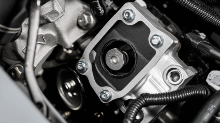
How Does a VGT or VNT Work Step by Step?
Let’s take a variable geometry turbocharger as a simple example.
1) Sensing engine conditions. The ECU watches engine speed and load. It also reads a boost pressure sensor. It reads an exhaust gas temperature sensor. It may read an engine speed sensor on the turbo shaft. It knows desired charge air pressure and air‑fuel ratio.
2) Actuator command. Based on that data the ECU sends a signal to a VGT electronic actuator or a pneumatic actuator VGT. The actuator moves the linkage.
3) Vane movement. The vane actuation rod turns the variable turbine vanes around the nozzle ring. In some designs you also see variable compressor vanes or compressor inlet guide vanes (CIGV).
4) Flow optimization. At low rpm the vanes close. Exhaust gas hits the turbine wheel at a sharper angle and higher speed. At high rpm they open. Back pressure falls and exhaust manifold pressure drops.
5) Result. Boost pressure control gets precise. Turbo lag reduction is strong. Compressor stall prevention improves. The engine runs in optimal points more often. You feel clean pull and better engine response.
You may ask about wastegate vs VGT. A wastegate bypasses exhaust around a fixed turbine to limit boost. A VGT instead changes turbine geometry. It controls turbine speed directly with the vanes. VGT gives finer control over transient response and steady boost. Many diesel engine technology platforms rely on VGT for this reason. Modern gasoline engine turbocharging uses it too with the right materials.
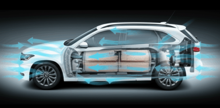
Where Do We Use VSVs in Cars and Jets?
You find variable vane tech in many fields.
- Automotive variable geometry or nozzle turbochargers (VGT or VNT):
- Diesel engines love VGT. You get strong low‑speed torque. You also get better EGR control to reduce emissions. Brands like Garrett VGT, BorgWarner VGT, Holset VGT, Honeywell VGT, and Siemens VGT show this at scale. Makers such as IHI and Mitsubishi Heavy Industries build systems too.
- Modern gasoline engines use VGT or VNT with high‑temp materials. That brings efficiency and power without twin turbos.
- Aircraft jet engines:
- Axial flow compressor stages use variable inlet guide vanes (VIGV) and multi‑stage stators. They adjust for takeoff, climb, cruise, and descent. This prevents compressor stall during rapid throttle changes and at varied altitudes.
- Many turbofan engines shape flow with variable diffuser vanes as well. Jet engine compressors need a wide surge margin. VSVs deliver that.
- Industrial gas turbines:
- Power generation and oil and gas sites use VSVs in gas turbines. You get better part‑load efficiency and faster ramp-up and ramp-down. That helps combined cycle power plants meet grid swings.
Jet engines and gas turbines share the same basics. The compressor and the turbine care about airflow dynamics and aerodynamic forces. VSVs let them work smart across a broad map.
What Gains Do You Get in Power, Torque, and Fuel Economy?
Problem: You want both quick launch and strong top end. You also need lower fuel use and lower emissions. Fixed systems force a trade.
Agitate: A heavy car feels lazy out of a turn. A truck strains up a hill. A plane risks surge on climb. The engine burns extra fuel and runs hot. Emissions go up.
Solution: VSVs open the door to both. Here is what you can expect when you tune and size it right.
- Enhanced engine performance
- Reduced turbo lag. Faster spool at low rpm gives you that snap. Tests show up to 50% faster spool-up time in some VGT diesel engines.
- Increased low-speed torque. Gains of 10–25% at about 1500 rpm are common in VGT equipped passenger car engines.
- Optimized high-end power. The system keeps boost steady at high engine speeds. High-speed power stays strong.
- Improved fuel efficiency
- Better use of exhaust energy in turbines. You boost turbocharger efficiency. That trims specific fuel consumption by 3–7% in many cases.
- Optimal compressor operation across loads. You extend the useful compressor map by 15–25% so the engine lives near its best points more often.
- Reduced emissions
- Precise air‑fuel ratio control and better combustion. CO2 falls with fuel use. Cuts can reach up to 10% indirectly.
- Better EGR match. With a VGT you can set exhaust manifold pressure to drive exhaust gas recirculation. That reduces NOx by lowering burn temperature.
- Preventing compressor surge and stall
- Variable stators hold stable airflow. They guard the surge line during transients. They also push the choke line out a bit. That extends the engine’s usable range.
You gain on all fronts. Power. Torque. Fuel economy. Emissions reduction. That is rare in engine work. VSVs make it real.
How Do Sensors and the ECU or FADEC Control the Vanes?
Smart control makes the hardware shine.
- The engine management system reads the world:
- Engine speed sensor tracks rpm.
- Boost pressure sensor tracks charge air pressure.
- Exhaust gas temperature sensor protects the turbine inlet temperature.
- Load input maps the driver’s demand or the pilot’s throttle.
- The ECU or FADEC runs a strategy:
- In closed-loop control the ECU compares desired boost pressure with actual. A PID controller corrects error fast without overshoot.
- At times open-loop control handles quick steps to improve transient response. The code then blends back to closed loop for precision.
- The actuator moves the vanes:
- VGT electronic actuators use compact motors and gears. They give fine position control.
- Pneumatic actuators use air pressure and a spring. They are simple and robust.
- The linkage mechanism ensures synchronized movement of all vanes. This keeps the nozzle ring and the variable area nozzle accurate under load and heat.
With tight control you keep the compressor inlet area and the turbine outlet area where you want them. You guide exhaust flow characteristics and intake air flow optimization in real time. That yields stable engine operation points and smooth engine performance curves you can count on.
Fixed vs Variable Stator Vanes: What’s the Difference?
Problem: Fixed geometry does one thing well at one point. Many drivers and pilots need more than that.
Agitate: You either size the turbo large and live with low-end lag or size it small and lose high-end power. You accept surge risk or you limit the throttle. You carry extra hardware like twin-turbo systems.
Solution: Variable vanes give you range. They act like a transmission for airflow. Fixed stators set direction and cannot adjust. Variable stators change blade angle. They steer flow to match engine speed and load. With VSVs you can:
- Shape pressure ratio and mass flow rate to a wider map range.
- Guard the compressor against stall and surge. You keep a healthy surge margin.
- Cut turbo lag without a wastegate bleed. You avoid dumping exhaust energy for control.
Fixed geometry still works in many cases. It is cheap and simple. Yet when you need flexibility and efficiency across the drive cycle VSVs win on results.
What Can Go Wrong and How Do You Maintain VSVs?
Problem: Moving parts live in hot gas. Soot and heat cause problems.
Agitate: Vanes stick. Linkage wears. Actuators fail. The turbo goes into limp mode. You get DTC codes and poor drivability.
Solution: Know the issues and plan service.
- Carbon buildup in VGT units can make sticky vanes. This hits many older diesel engines above 100K miles. You may need VGT cleaning or turbo replacement.
- Actuator malfunctions are rarer yet still happen. Electronic actuators can fail from water or heat. Pneumatic units can leak.
- Linkage wear causes imprecise vane positioning. That hurts boost pressure control and may trigger VGT recalibration.
- Complexity and cost are higher than fixed units. The trade pays off with performance and fuel savings. Keep clean oil and good fuel. Run proper warm-up and cool-down. These habits extend life.
When you fix the cause you save the turbo. You also keep emissions devices happy. EGR works better when the VGT sets back pressure with care.
What About Design Details, Materials, and Actuators?
Design choices make or break a VSV system.
- Compressor and turbine basics:
- Axial flow compressor stages use rows of stators and rotors. Centrifugal compressor stages use radial flow. Both use guide vanes to trim inlet direction and velocity.
- Variable diffuser vanes can tune diffusion to avoid stall and to shape the compressor map.
- Aero details:
- Vane aerofoil shape and chord line set lift and drag on the flow. Blade angle adjustment sets the angle of attack. That controls airflow dynamics and aerodynamic forces.
- The nozzle ring frames the path for the variable turbine vanes. It must resist heat and wear.
- Actuator and control hardware:
- Many VGTs use electric actuators with gearboxes. The ECU watches position sensors and runs a PID controller. This gives smooth vane movement.
- Pneumatic actuators need good vacuum or pressure supply. They are simple to service.
- A robust vane actuation rod and linkage keeps all blades aligned under load.
- Materials:
- High grade alloys stand up to turbine inlet temperature. Coatings fight carbon buildup.
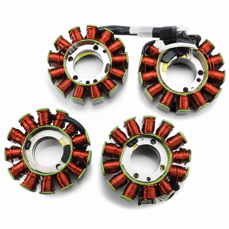
- Electric actuator motors and sensors use precision laminations in their cores. The quality of the stator core lamination inside those motors can impact accuracy and heat. For complex drives you may also require tight‑tolerance motor core laminations and balanced rotor core lamination. All of these rely on stable electrical steel laminations to cut loss and improve control.
Strong hardware and smart control work together. When both sides shine the turbo breathes like an athlete.
Data, Case Studies, and Results You Can Use
Here is a quick table with typical impacts across fields. Real numbers vary by engine and duty cycle. These figures reflect common results reported by OEMs and in open literature.
| Category / Metric | Description / Typical Impact | Context / Application | Notes |
|---|---|---|---|
| Turbo lag reduction | Up to 50% faster spool | VGT diesel engines vs fixed turbo | Better low-end response and drivability |
| Low-end torque | 10–25% gain at ~1500 rpm | VGT gasoline and diesel | Small engines mimic larger ones |
| Compressor map range | 15–25% wider useful range | Single turbo setups | Less need for twin-turbo |
| Specific fuel consumption | 3–7% reduction | VGT/VNT in road engines | Better exhaust energy recovery |
| CO2 emission | Up to 10% down indirectly | Linked to fuel economy | Meets strict regs like Euro 6 and EPA Tier 3 |
| NOx control | Higher EGR rates enabled | Back-pressure control via VGT | Lower combustion temperature |
| Surge margin | Significantly increased | Axial compressors in turbofans | Safe operation across altitudes and transients |
| Overall engine efficiency | 2–4% improvement | Turbofans with VIGV and variable stators | Lower fuel burn per passenger mile |
| Part-load efficiency | 5–10% better at 50–75% load | Industrial gas turbines | Better economics and flexibility |
| Operational flexibility | Faster ramp-up/down | Combined cycle plants | Improved start-up and shutdown |
| Carbon buildup impact | 15–20% of older units >100K mi | Diesel VGTs | Sticky vanes and limp mode |
| Actuator failure rate | <5% over lifespan | Electronic actuators | Less common than sticking issues |
Note how these gains tie back to core ideas. VSVs reshape the pressure ratio and mass flow rate relationship. They push back the surge line and avoid the choke line. They improve turbocharger sizing freedom. You can pick a wheel size that works with the variable nozzle to hit both transient response and steady-state operation goals.
What’s Next for Variable Vane Tech?
Problem: Engines keep pushing for more. Tougher emissions. Lower fuel burn. Quicker transient response. Lighter weight.
Agitate: Fixed hardware cannot keep up. Old control code wastes potential. Materials face heat and stress. Costs climb.
Solution: The future is bright.
- Integration with hybrid powertrains. VSVs will blend with e‑boost and motor assist. That lets the engine downsized yet lively.
- Advanced materials for durability and lighter designs. New alloys and coatings resist heat and carbon buildup. Lighter linkages cut inertia and improve control.
- Smarter control algorithms. Model‑based and adaptive strategies can switch between open-loop control and closed-loop control as needed. Better maps use engine speed, load, exhaust manifold pressure, and charge air pressure to pick vane angles on the fly.
- Broader use in aerospace jet engines and industrial gas turbines. Expect tighter FADEC links, deeper stall margin control, and higher aerodynamic efficiency without a surge penalty.
When design meets control the result feels like magic. You press the pedal and the engine answers now.
FAQs
Q: Are VNT and VGT the same thing
A: Both describe variable geometry in the turbo. VNT stands for variable nozzle turbocharger. VGT stands for variable geometry turbocharger. Many people use them interchangeably.
Q: Do variable stator vanes help gasoline engines
A: Yes. With the right materials you can run VGT on gasoline. You gain transient response and high-end power. You also improve fuel economy.
Q: What stops compressor surge
A: Smart vane angles direct flow and hold a safe surge margin. The ECU or FADEC uses a PID controller to keep boost stable during fast throttle moves.
Key Takeaways
- Variable stator vanes act like adjustable blinds for airflow. They change angle to guide exhaust gas or air.
- VGT and VNT cut turbo lag. They boost low-speed torque and hold high-speed power.
- VIGV and variable stators in axial compressors prevent stall and expand the surge margin.
- Smart control with sensors and a PID controller keeps boost pressure on target.
- VSVs improve specific fuel consumption and reduce CO2 and NOx via better EGR.
- Maintenance matters. Clean oil and proper duty cycles reduce carbon buildup and sticky vanes.
- Design choices like aerofoil shape, chord line, and vane actuation rod quality affect life and performance.
- Quality laminations inside electric actuators help precise vane control. Good stator and rotor cores reduce heat and loss.
- Fixed geometry is simple yet narrow. Variable geometry gives range and efficiency.
- The future blends VSVs with hybrid systems, new materials, and smarter code.
References
- Garrett Motion. Turbocharger Fundamentals and VNT/VGT Technical Guides.
- BorgWarner. Variable Turbine Geometry Product Literature.
- Cummins Holset. VGT Technology White Papers.
- Rolls-Royce. The Jet Engine. Technical handbook on axial compressors and turbines.
- SAE International. Papers on compressor surge, stall margin, and VIGV control.
- GE Aviation and Pratt & Whitney open technical briefs on FADEC and compressor variable geometry.
Bonus: How All the Key Ideas Fit Together in Real Engines
Let’s tie a bow on the many parts we covered. A turbocharger has a compressor and a turbine. The compressor may be a centrifugal compressor with a radial flow compressor wheel. The turbine housing directs exhaust gas flow to the wheel. Variable turbine vanes and a nozzle ring live in that housing. The actuator and the linkage mechanism adjust vane angles. The ECU watches engine speed and load. It reads boost pressure control targets and protects turbine inlet temperature. The system picks vane angles to match engine operation points.
Inside an axial compressor such as in a turbofan jet engine the variable inlet guide vanes and variable stator vanes set airflow dynamics into each rotor blade row. They adjust angle of attack so the rotor sees the right direction and velocity. They improve aerodynamic efficiency across all flight phases. They also help prevent compressor surge during transients and raise the steady-state operation range. The FADEC runs a control strategy that may use a PID controller and sensor feedback for engine speed and temperature. This keeps mass flow rate and pressure ratio in a safe band far from the surge line or choke line.
Modern turbocharging borrows from aerospace jet engines and industrial gas turbines. Wastegate vs VGT is a key choice in diesel engine technology and gasoline engine turbocharging. VGT gives transient response and strong low-end torque while fixed geometry with a wastegate is simpler. VGTs from Garrett Motion, BorgWarner, Holset, Honeywell, Siemens, IHI, and Mitsubishi Heavy Industries show many forms. Some add compressor inlet guide vanes or variable diffuser vanes for even tighter control. Others focus on turbine speed control and exhaust energy recovery in power generation turbines.
In every case the secret lies in how variable vane geometry shapes the compressor map and the turbine map. By tuning the compressor inlet area and the turbine outlet area you bend the engine performance curve to your benefit. You raise engine power output when you need it. You lower specific fuel consumption when you cruise. You cut emissions with better air‑fuel ratio control and a strong partner to exhaust gas recirculation. You keep exhaust manifold pressure in the right window. You also reduce turbocharger failure modes tied to surge and overspeed.
Yes you must care for the system. Carbon buildup can cause sticky vanes in older diesel engines. Plan VGT cleaning as needed. Watch for VGT actuator problems and linkage wear. Keep software current for VGT recalibration after service. Use sensors like the engine speed sensor, boost pressure sensor, and exhaust gas temperature sensor to catch issues early. With good care you enjoy optimal turbo performance for a long time.
Finally a word on the motors inside electric actuators. They need precise magnetic paths to hit position targets. This is where the quality of laminations matters. Tight stack tolerances, low core loss, and stable magnetic properties improve actuator response and heat control. If you source or design actuators you will want to look into high quality stator and rotor stacks. You can start with proven suppliers who focus on performance and consistency. Explore modern options in stator core lamination, premium motor core laminations, balanced rotor core lamination, and low‑loss electrical steel laminations. When the core parts are right the vane moves right. That is how you meet the need and position your product as the trusted solution.