How to Wire a Stator to Charge a Battery: A Comprehensive DIY Guide
Table of Contents
- Introduction: Why I Built and Rewired Stator Charging Systems
- Charging System Basics You Must Know
- What a stator does
- Rectifier vs regulator
- AC vs DC in plain English
- Single-phase vs three-phase stators
- How the stator and rotor actually make power
- Essential Components and Tools I Use
- Safety First: Crucial Precautions Before You Start
- Step-by-Step Wiring: From Stator to Rectifier/Regulator to Battery
- Step 1: Identify your stator wires
- Step 2: Connect stator to rectifier/regulator (AC input)
- Step 3: Connect rectifier/regulator to battery (DC output)
- Step 4: Grounding and mounting best practices
- Step 5: Secure and insulate everything
- Testing Your Work With a Multimeter
- Pre-start checks
- Stator AC output test
- Regulator DC output test at the battery
- Load testing and ripple voltage
- Troubleshooting: No Charge, Overcharge, and Flicker Problems
- Battery not charging
- Battery overcharging
- Flickering lights or intermittent charging
- Finding shorts, opens, and bad grounds
- Real-World Examples From My Bench
- Motorcycle with three yellow wires and a MOSFET upgrade
- Small engine two-wire stator on a lawn mower
- Wire Gauge, Fuses, and Heat Management Tips
- Maintenance for Longevity and Reliability
- Quick Reference: Common Questions and Must-Know Numbers
- Conclusion: Wire it once, charge it right
Introduction: Why I Built and Rewired Stator Charging Systems
I started wiring stators because my own bikes and small engines kept killing batteries. One motorcycle overcharged like a runaway train. Another barely trickled. I learned to read a stator wiring diagram, test a rectifier regulator, and pick the right fuse and wire gauge. This guide distills those lessons. I’ll show you how to connect a stator to a rectifier/regulator, then to your battery, and how to test it so you know it works. You don’t need to be an electrical engineer. You do need to follow a few rules, use a multimeter, and respect AC and DC.
Charging System Basics You Must Know
What a stator does
A stator is a set of stationary coils that sits around a spinning rotor or flywheel. Magnets pass by the coils and the stator generates AC voltage. The faster the engine spins the higher the AC voltage climbs. In motorcycles, ATVs, UTVs, snowmobiles, outboard motors, and lawn mowers this “magneto” or alternator setup forms the backbone of the charging system. Some use permanent magnets. Others use excited field systems.
Rectifier vs regulator
The rectifier turns AC into DC. The voltage regulator keeps that DC within a safe window so your 12V battery charges without boiling or starving. Many units combine both functions into a single rectifier/regulator. You’ll often see this called a shunt regulator, series regulator, or MOSFET regulator. Each has pros and cons. Shunt types bleed off extra power as heat. Series types limit current upstream. Modern MOSFET units run cooler and hold voltage steadier.
AC vs DC in plain English
AC from the stator swings positive and negative. Your battery needs DC which sits above zero. That’s why you must run stator output into a rectifier regulator before it touches the battery. If you try to connect the stator directly to a battery you’ll have a bad day.
Single-phase vs three-phase stators
- Single-phase stators usually have two output wires. Often both are yellow. You connect both to the AC inputs of the rectifier/regulator.
- Three-phase stators usually have three output wires. Commonly three yellow leads. You connect all three to the AC inputs labeled “AC” or “Y” on a three-phase rectifier/regulator. There is no positive or negative on the AC side. Phase order doesn’t matter for rectification.
- Some older small engines use a two-wire stator with an internal ground. Some include a separate lighting coil. Know what you have before you crimp a single terminal.
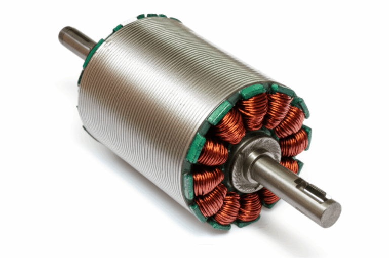
How the stator and rotor actually make power
A rotor packed with magnets spins past the stator windings. Magnetic fields induce current in the coils. Those thin copper windings sit in laminated steel to direct flux and reduce eddy current losses. Good lamination design matters because heat is the stator’s worst enemy. If you ever rebuild or spec components you’ll see how the quality of the stator core lamination and the matching rotor core lamination affects efficiency and durability. Manufacturers stack precise motor core laminations from low-loss electrical steel laminations for better performance and cooler operation.
Essential Components and Tools I Use
Key components
- Stator: Existing or new. Single-phase or three-phase.
- Rectifier/Voltage Regulator: Combined unit for your stator type. MOSFET, shunt, or series regulator options.
- 12V Battery: Lead-acid or lithium-ion with a proper BMS that supports charging from vehicle systems.
- Appropriate Gauge Wire: 12–16 AWG for main charging lines depending on length and current.
- Inline Fuse Holder and Fuse: Size to protect the wire and system. I use 15–30A on many 12V charging systems.
- Electrical Connectors: Quality ring terminals, spade connectors, sealed crimp connectors. Use proper crimp tool. Solder where needed.
- Mounting Hardware: Bolts, lock washers, and a solid heat sink surface for the regulator.
Tools
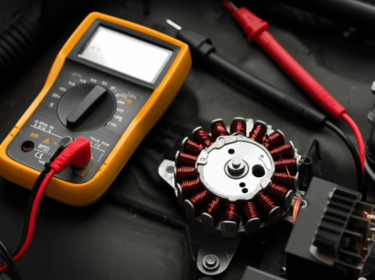
- Multimeter: Volts AC, volts DC, resistance, continuity. Diode testing helps too.
- Wire Strippers and Crimpers: Use good ones. They save headaches.
- Soldering Iron and Heat Gun: For solid connections and heat shrink tubing.
- Electrical Tape and Heat Shrink: Weatherproofing and strain relief.
- Wrenches/Sockets: For terminals and mounting.
- Safety Glasses and Gloves: Batteries and spinning engines bite.
Safety First: Crucial Precautions Before You Start
- Disconnect the battery before any wiring. Remove the negative terminal first.
- Avoid short circuits. Cover exposed wires. Keep tools clear of terminals.
- Work in a ventilated space. Lead-acid batteries vent hydrogen while charging.
- Respect current and voltage. Don’t probe live wires unless you know what you’re measuring.
- Fuse the battery positive output that feeds the harness. The fuse protects the wire and your ride.
- Keep the regulator on a cool, clean surface with airflow. Overheating kills rectifiers.
Step-by-Step Wiring: From Stator to Rectifier/Regulator to Battery
Step 1: Identify your stator wires
I look for two or three wires from the stator. Most are yellow. Two yellows usually mean single-phase. Three yellows point to three-phase. Some stators have a ground wire or a case ground. Verify with a multimeter.
- Continuity test: Each pair of stator wires should have low resistance between them. Expect 0.1–1.0 ohm per phase in many systems. Infinite resistance means an open coil.
- Ground test: Check each stator wire to engine ground. Many permanent magnet stators should not show continuity to ground on the AC leads. If you read a short to ground on an output lead you likely have a failed winding or a design that uses a grounded coil. Confirm with your service manual.
Step 2: Connect stator to rectifier/regulator (AC input)
- Match the stator AC leads to the rectifier/regulator AC inputs. These may be labeled “AC”, “~”, or “Y”.
- Two-wire stator: Connect both to the two AC inputs. Polarity does not matter on AC inputs.
- Three-wire stator: Connect each to one of the three AC inputs on a three-phase rectifier. Order does not matter.
- Use sealed connectors or heat shrink butt splices. You want weatherproof joints on a motorcycle stator wiring harness or an ATV stator wiring harness. Corrosion kills charging systems fast.
- Route wires away from the exhaust and moving parts. Cable ties help. Add abrasion sleeves where wires cross metal edges.
Step 3: Connect rectifier/regulator to battery (DC output)
- Positive (+): Find the regulator’s DC positive output. It’s often a red wire or a post labeled “+” or “B+”.
- Install an inline fuse in the positive line. Place it as close to the battery as practical. A 15–30A fuse works for many setups depending on stator output amps and wire gauge.
- Connect the fused positive lead to the battery positive terminal with a ring terminal and a clean, tight connection.
- Negative (–) or Ground: Find the regulator’s DC negative output. Often black. Sometimes green is chassis ground on certain brands.
- Connect to the battery negative terminal or a verified chassis ground with low resistance back to the battery. Check continuity with the multimeter to be sure.
Step 4: Grounding and mounting best practices
- Some regulators need a separate chassis ground wire. Don’t skip it. A floating or high-resistance ground causes undercharging or erratic voltage.
- Mount the rectifier/regulator on a solid metal surface that acts like a heat sink. Give it airflow. I’ve fixed “dead” charging systems simply by remounting the regulator where it can shed heat.
- Avoid paint under ground lugs. Bare metal gives a better ground path.
Step 5: Secure and insulate everything
- Crimp with the correct die for your connector size. Tug test every crimp.
- Solder if the connector or environment demands it. Then apply heat shrink tubing.
- Wrap harness sections in friction tape or split loom. Keep wires from rubbing on sharp edges.
- Use proper wire routing. Avoid tight bends. Leave service loops where needed.
Testing Your Work With a Multimeter
Pre-start checks
- Double-check polarity. Positive to positive. Negative to negative.
- Confirm the fuse is in place.
- Verify continuity from regulator ground to battery negative.
- Make sure the battery is connected correctly and in good shape. A dead or sulfated lead-acid battery can confuse your testing.
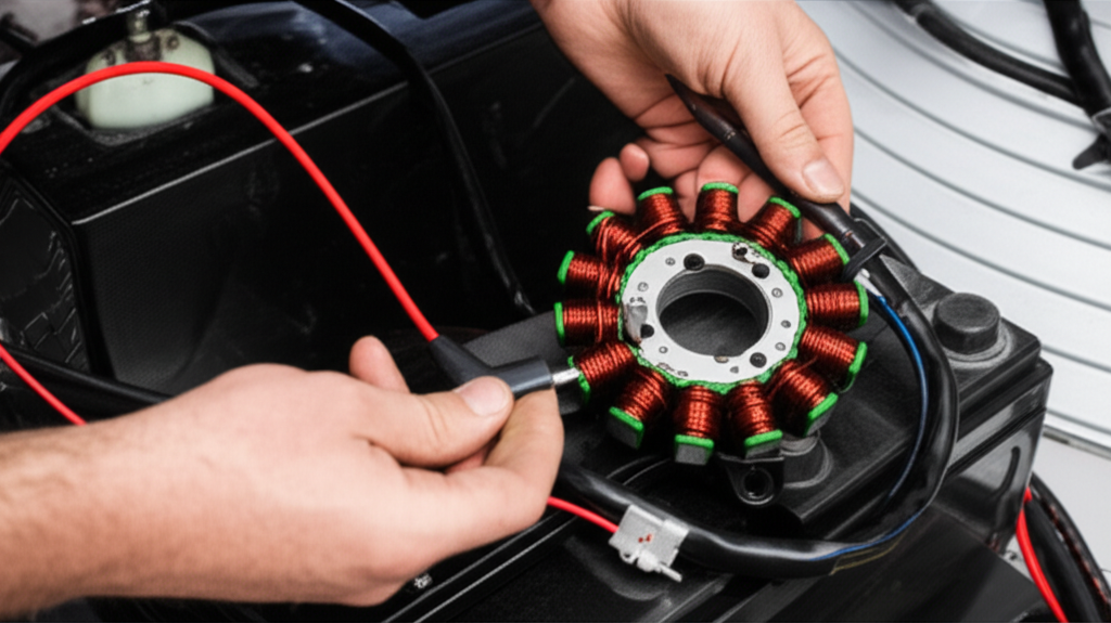
Stator AC output test
- Unplug the stator from the regulator or backprobe at the connector.
- Set the multimeter to AC volts.
- Start the engine. At idle you might see 20–30 VAC on a single-phase stator and 15–40 VAC per phase on a three-phase stator.
- Raise RPM. Healthy systems often produce 20–70 VAC per 1000 RPM with no load. This varies by design and flywheel magnet strength. You’re looking for smooth increases with RPM. A dead phase stays low. A short to ground can drag the reading down.
Regulator DC output test at the battery
- Reconnect the stator to the regulator.
- Set the meter to DC volts.
- Measure across the battery terminals with the engine running.
- At moderate RPM you should see 13.8–14.8 VDC on most 12V lead-acid systems. That range charges well without cooking the battery. Some lithium-ion BMS units prefer tighter control. Check the battery maker’s specs.
Load testing and ripple voltage
- Turn on headlights or accessories. Watch the battery voltage. It should hold near 13.8–14.8 VDC at moderate RPM.
- If you suspect a weak rectifier diode check ripple. Set the meter to AC volts and measure across the battery while the engine runs. You want low ripple. A failing diode creates higher AC ripple and dimming or flicker under load.
- Voltage drop testing helps too. Measure from the regulator positive to the battery positive under load. Anything more than a few tenths of a volt points to undersized wire or a bad connection.
Troubleshooting: No Charge, Overcharge, and Flicker Problems
Battery not charging
- Faulty stator: Check resistance per phase. Look for an open circuit or a short to ground. I’ve found stators with heat-damaged windings that read fine cold yet break down hot. Test at operating temperature if needed.
- Defective rectifier/regulator: If the stator AC checks out yet the battery voltage stays low you likely have a bad regulator. Swap with a known-good unit or bench test if you have the gear.
- Loose or corroded connections: Clean every ring terminal. Check grounds. That includes the regulator case if it acts as ground.
- Blown fuse: Replace with the correct rating. A higher fuse will not fix a short. Find the cause.
- Undersized wire: Voltage drop will steal your charging current. Upgrade to 12–14 AWG on longer runs.
Battery overcharging
- Failed voltage regulator: Classic shunt regulator failure sends voltage into the stratosphere. You’ll see 15.5V or more at the battery. Stop the engine before the battery vents or boils.
- Poor ground: The regulator uses ground as a reference. A weak ground path can make the regulator misread system voltage and overcharge.
Flickering lights or intermittent charging
- Loose connectors or bad crimps: Wiggle test the harness while watching the meter. If the numbers dance you found something.
- Heat-soaked regulator: Poor mounting or no airflow can cause intermittent cutouts.
- Intermittent stator coil: Heat can open cracked windings. Check resistance hot.
Finding shorts, opens, and bad grounds
- Continuity test the ground path with the battery disconnected. You want near-zero ohms from the regulator ground to the battery negative.
- Use the multimeter’s diode test on rectifiers if you can access the pins. A shorted diode reads low in both directions. An open diode reads infinity in both directions.
- To track a short circuit remove loads and check if the fuse still blows. Isolate sections of the harness. Don’t shotgun parts.
Real-World Examples From My Bench
Motorcycle with three yellow wires and a MOSFET upgrade
I had a sportbike that cooked two shunt regulators. The stator tested fine on AC output but the regulator ran hot and the battery saw 15.3V at cruise. I replaced the unit with a MOSFET regulator. I used 12 AWG wire from the regulator to the battery. I mounted it on a metal bracket with airflow. Charging settled at 14.4V and the headlight flicker disappeared. The wiring diagram showed three yellow stator leads into the regulator labeled “Y” and red/black DC outputs to the battery with a 30A fuse. Simple and solid.
Small engine two-wire stator on a lawn mower
A friend’s mower wouldn’t charge after a stator replacement. The two yellow stator wires went to the regulator marked “AC”. The red DC output went to battery positive through a 20A fuse. The black went to ground. It still undercharged at 13.1V. I found a corroded ground lug on the frame. After cleaning to bare metal the battery held 14.2V at mowing RPM. That little fix saved a battery and a Saturday.
Wire Gauge, Fuses, and Heat Management Tips
- Choose wire gauge based on current and length. For most 12V charging lines I use 12–14 AWG. Short runs with lower current can get away with 16 AWG. Use an automotive wire gauge chart if in doubt.
- Fuse rating should protect the wire. A 12 AWG wire typically pairs well with a 25–30A fuse for short runs on charging systems. Size also depends on the stator output amps.
- Mount the regulator where it breathes. Add a small heat sink if the bracket gets hot. Heat kills semiconductors. Keep mud and debris off fins on ATVs and dirt bikes.
- Use quality connectors. Good crimp terminals with heat shrink beat cheap vinyl-insulated ones. Solder splices in high-vibration spots if you can. Finish with heat shrink.
- Secure wire routing. Tie harnesses every few inches. Add abrasion sleeves where wires pass near the frame. Prevent shorts by avoiding sharp bends and hot surfaces.
Maintenance for Longevity and Reliability
- Inspect wiring and connections every oil change. Look for chafed insulation, loose ring terminals, and corrosion.
- Keep the regulator clean. Airflow matters for cooling. Brush off dirt and debris.
- Clean battery terminals. A dab of dielectric grease helps prevent corrosion on exposed connections.
- Check resting battery voltage. A healthy 12V lead-acid battery sits at 12.6–12.8V after resting. Anything much lower suggests discharge or age.
- If the machine sits use a battery maintainer. A smart tender keeps the battery topped without overcharging.
- For lithium-ion batteries verify your regulator’s charging profile. Many lithium packs include a BMS yet they still need proper 13.8–14.4V output and solid grounds.
Quick Reference: Common Questions and Must-Know Numbers
What voltage should I see at the battery when charging
- Aim for 13.8–14.8 VDC at moderate RPM. That range charges lead-acid well without boiling. Lithium systems prefer tighter control so check the BMS specs.
What AC voltage should the stator produce
- It varies by engine and stator. As a rough guide I often see 20–70 VAC per 1000 RPM with no load. Look for voltage that climbs with RPM on every phase.
How do I test a stator with a multimeter
- Resistance: 0.1–1.0 ohm per phase in many systems. Check your service manual if you have exact specs.
- Continuity to ground: Most permanent magnet stators should not show continuity from an AC output lead to ground. Some designs do so confirm with documentation.
- AC output running: Measure between stator leads. Voltage should rise with RPM.
How do I test a rectifier/regulator
- Verify stator AC input is healthy. Then measure DC at the battery. If AC looks good yet the battery voltage stays under 13.5V you likely have a regulator issue.
- Diode test across rectifier leads if you can access them. You should see current flow one way and block the other.
What fuse should I use
- Typical systems use 15–30A fuses on the charging line to the battery. Choose based on wire gauge and stator output. I prefer to err on protecting the wire not the component.
Which regulator type should I choose
- Shunt regulators are common and cheap. They get hot.
- Series regulators run cooler because they limit current instead of burning it off.
- MOSFET regulators deliver steadier voltage and lower heat. They cost more and they’re worth it on bikes that eat regulators.
How do I wire two-wire vs three-wire stators
- Two-wire stator: Both wires to the AC inputs of the rectifier/regulator. Polarity doesn’t matter.
- Three-wire stator: Each of the three wires to one of the three AC inputs on a three-phase rectifier/regulator.
Can I run LED lights from the stator
- Yes through the battery and regulator. Do not connect LEDs directly to raw AC. LEDs prefer stable DC. You can calculate accessory current draw and confirm the stator’s power output can keep up.
What about universal regulator wiring and color codes
- Many aftermarket units follow red for B+, black for B–, and yellow for stator AC leads. Yet color codes vary by brand. Always read the schematic. If in doubt call the manufacturer.
What’s the difference between single-phase vs three-phase rectifiers
- Single-phase rectifiers have two AC inputs and two DC outputs. Three-phase units have three AC inputs and two DC outputs. Three-phase systems charge more smoothly with less ripple.
How do I diagnose parasitic drain
- With the engine off remove the negative battery cable and place the multimeter in series on DC amps. If you see more than a few tens of milliamps on small powersports machines start pulling fuses to isolate the circuit. Some accessories and ECUs draw a little current at rest. Large draws will drain batteries overnight.
Diagrams you may see and what they mean
- “Y” or “AC” on a regulator: Connect stator leads here.
- “B+” or red: Battery positive output from the regulator through a fuse.
- “B–” or black/green: Battery negative or chassis ground.
A Word on Components and Build Quality
I learned the hard way that cheap parts cost more. Poorly wound coils and low-grade steel laminations run hot. They fail early. Bikes with higher output lighting or heated gear need robust stators and steady regulators. When you dig into the guts of an alternator you’ll find laminated steel cores. Better laminations reduce eddy current loss and heat. That matters for reliability. If you ever source or compare components you’ll see the link between lamination quality and charging performance in action.
Integrating Related Concepts Without the Jargon
- Ohm’s Law helps when you size wires and calculate voltage drop. Low resistance connections deliver more current and less heat.
- Kirchhoff’s Laws explain why bad grounds wreak havoc. Every amp that leaves the battery must return. If the return path has high resistance you’ll get weird readings and weak charging.
- Ripple voltage can kill sensitive electronics and cause LED flicker. Three-phase rectifiers and good regulators keep ripple low.
- Use proper wire insulation and heat shrink tubing. Keep moisture out and the harness lasts.
Bringing It All Together: A Walkthrough Checklist
- Identify stator type: two-wire or three-wire. Confirm with a continuity and resistance test.
- Choose the right rectifier/regulator: match phase type and consider a MOSFET or series unit for cooler operation.
- Select wire gauge and fuse: 12–16 AWG and a 15–30A fuse based on output and run length.
- Route and connect AC leads from stator to the regulator.
- Install inline fuse then connect regulator B+ to battery positive.
- Connect regulator negative to battery negative or a proven chassis ground.
- Mount the regulator on a cool surface with airflow. Clean the ground contact.
- Start the engine and test:
- Stator AC rises with RPM.
- Battery sees 13.8–14.8V at moderate RPM.
- Under load the system holds voltage.
- Ripple stays low.
- Fix what the meter tells you. Don’t guess.
Extra Tips I Lean On
- Disconnect the battery before wiring. It saves fuses and nerves.
- Use a battery maintainer if the vehicle sits. Batteries hate being left discharged.
- If you upgrade to lithium confirm your regulator’s voltage window and the battery’s BMS requirements.
- Keep spare fuses on hand. Testing sometimes pops one.
- Consider a small voltmeter on the dash or bars. You’ll know at a glance if the charging system plays nice.
Conclusion: Wire it once, charge it right
Wiring a stator to charge a battery sounds technical. It isn’t magic. You identify the stator output, feed it into the correct rectifier/regulator, then deliver clean DC to the battery through a fused positive and a solid ground. You test your work with a multimeter. You fix what the meter shows you. That’s the entire game.
I’ve wired motorcycles, ATVs, lawn mowers, and small boats using this approach. The details change a little with two-wire versus three-wire stators or shunt versus MOSFET regulators. The principles stay the same. Keep the wiring clean. Keep the regulator cool. Keep the battery protected with a proper fuse. Do that and you’ll ride more and wrench less.