How to Test Your Stator and Rectifier (Regulator) – A Complete DIY Diagnostic Guide
Table of contents
- Introduction: Why your charging system matters
- Safety first: Precautions that protect you and your ride
- Tools and materials I use for charging system diagnostics
- Preliminary checks: Battery and wiring come first
- Stator 101: What it does and how it fails
- How to test the stator step by step
- Rectifier/Regulator 101: What it does and how it fails
- How to test the rectifier/regulator step by step
- Interpreting your results: Fast decision paths
- Advanced checks: Ripple, voltage drop, and intermittent faults
- Common mistakes and pro tips from my bench
- FAQs that save time and money
- Conclusion: Keep your charging system healthy for the long haul
Introduction: Why your charging system matters
I’ve chased charging system gremlins on motorcycles, ATVs, boats, and small engines for years. The story usually starts the same way. The battery dies after a ride. The headlight goes dim at idle. The engine sputters or dies when you turn on extra lights. You think the battery is toast. Sometimes it is. Often it isn’t.
The stator and rectifier/regulator do the heavy lifting behind the scenes. The stator generates AC power. The rectifier converts that AC to DC and regulates voltage so the battery charges safely. When one of those two goes south you get classic symptoms: weak battery, no charge, flickering gauges, overcharging, or random stalling. I’ve seen riders replace a battery three times before realizing the stator had a short to ground. I’ve also seen a regulator cook a battery until it bulged like a loaf of bread.
In this guide I’ll show you exactly how I diagnose a motorcycle charging system. The same method works on ATVs, UTVs, snowmobiles, small boats with PMG charging, and many small engines. I’ll explain the tools, the tests, the expected numbers, and the “what now” decisions. You’ll save time. You’ll save money. You’ll stop guessing.
Safety first: Precautions that protect you and your ride
I love a good diagnostic session, but I respect electricity. You should too. Here’s how I stay safe and avoid creating new problems.
- Disconnect the battery negative terminal first when you’re pulling connectors or moving tools near live circuits. Reconnect it last.
- Wear safety glasses and gloves. You’ll deal with battery acid, sharp edges, and hot parts.
- Work in a well-ventilated space. Charging systems create heat and some batteries vent gas.
- Keep metal jewelry and loose tools away from battery terminals. A wrench across the posts acts like a toaster.
- Understand that stator AC voltage can climb high at RPM. I’ve seen 70 VAC per phase at 5,000 RPM on some three-phase units. Treat it with respect.
- Use a digital multimeter with good leads and intact insulation. A bad lead lies to you.
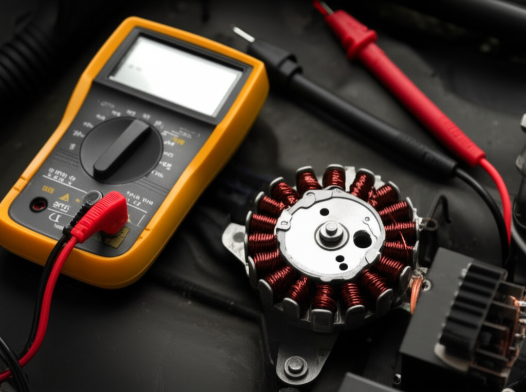
Tools and materials I use for charging system diagnostics
You don’t need a full shop to do this right. I reach for:
- Digital multimeter (DMM) with DC volts, AC volts, ohms, and diode test functions
- Basic hand tools: wrenches, screwdrivers, wire brush
- Battery charger or maintainer
- Service manual or wiring diagram for your model
- Test light for quick continuity checks
- Contact cleaner, dielectric grease, and a small pick for connectors
- Infrared thermometer for heat checks on the regulator
- Inductive current clamp if I want to measure charging current
- Safety glasses and gloves
I also value good components. The quality of the stator core and its laminations affects heat, efficiency, and life. If you want to understand why core material matters you can skim how a stator core lamination stack reduces eddy currents and heat. It’s not just a coil and magnets. The iron matters.
Preliminary checks: Battery and wiring come first
I never start with the stator. I start with the battery and the basic wiring. You should too. It’s the fastest path to a real answer.
1) Battery health assessment
- Visual inspection: I look for bulging, cracks, low electrolyte, and corrosion. White or green fuzz around terminals points to high resistance and voltage drop.
- Static voltage test: With the engine off and the battery at rest I expect about 12.6 V on a healthy fully charged 12‑volt battery. 12.2 V is roughly 50% state of charge. Anything under 12.0 V needs charging before you test the system.
- Load test: If I have a load tester I use it. A battery can show 12.6 V open circuit and still collapse under load. A quick headlight test also helps. Lights on for 2 minutes then crank. Slow cranking and a big voltage dip suggests a weak battery.
2) Wiring and connection inspection
- I check the charging circuit from stator to regulator to battery. I look for chafed wires, melted connectors, and loose pins. Stator leads often carry a lot of current. Heat loosens poor crimps.
- I clean battery terminals and grounds with a wire brush. I coat with dielectric grease after I torque them tight.
- I verify fuses related to charging. Some systems protect the regulator to battery feed with a main fuse.
You can spend an hour testing the stator and miss the real problem. Corroded battery terminals and a loose ground will mimic a bad rectifier every time.
Stator 101: What it does and how it fails
The stator is simply copper windings arranged around an iron core. The flywheel carries magnets. As the engine spins the magnets sweep past the windings and induce AC voltage. On power sports gear the stator often operates as a permanent magnet generator (PMG). You’ll see single-phase (two wires) or three-phase (three wires, usually yellow) stators.
Common stator failures I’ve seen:
- Short to ground from insulation breakdown. Heat and oil contamination accelerate it.
- Open circuit in a winding. A broken connection or burned section kills output on that phase.
- Weak output from heat damage. It passes an ohms test cold yet falls flat under load.
- Contamination on connectors that adds resistance and heat.
The core and lamination quality influence efficiency and heat. If you’re rebuilding or upgrading you can read about motor core laminations and why the steel stack design matters across machines.
How to test the stator step by step
You’ll perform three primary tests. Resistance between windings. Continuity to ground. AC output with the engine running. I’ll walk you through each one.
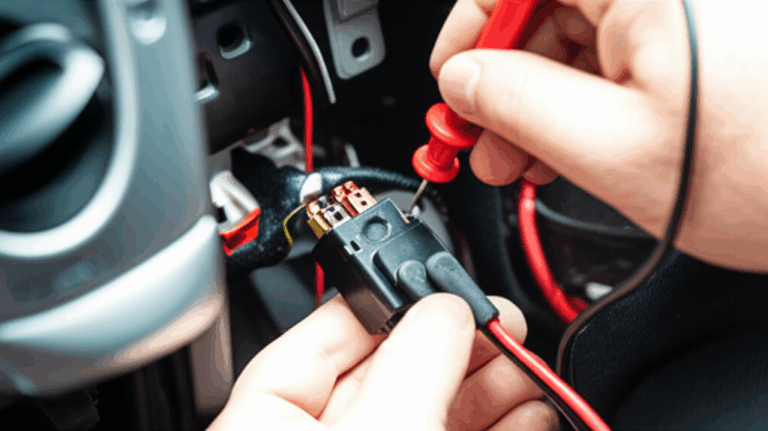
Step 1: Locate and disconnect the stator connector
- Find the harness coming out of the engine case. It usually ends in a connector with two or three yellow or white wires. Disconnect it from the rectifier/regulator.
- Inspect the connector. Brown discoloration and brittle plastic point to heat and high resistance.
Step 2: Resistance (ohms) test between stator windings
- Set your multimeter to low ohms. Use the 200 Ω range or auto-range.
- For a three-phase stator test A‑B, B‑C, and C‑A. For a single-phase stator test the two leads against each other.
- Expect very low readings and consistency. On many bikes I see 0.1 to 1.0 Ω. Your service manual gives the exact spec. I care most about matching values across pairs.
- If you see “OL” or a big mismatch you likely have an open circuit or a partially burned winding.
Step 3: Ground continuity test from each stator lead to ground
- Keep the stator disconnected. Set the meter to ohms or continuity buzzer.
- Probe one meter lead on a stator pin and the other on a clean engine ground or the battery negative.
- You should see no continuity. “OL” is good. Any resistance or a beep means the winding is shorted to ground. That stator will not charge.
Step 4: AC voltage output test with the engine running
- Leave the stator disconnected from the regulator during this test. We want raw AC.
- Set the meter to AC volts on a high range like 200 V~.
- Start the engine and measure between A‑B, B‑C, and C‑A at idle then at 3,000 to 5,000 RPM.
- Voltage should rise with RPM and match across phases. I often see 20 to 30 VAC at idle then 50 to 70 VAC at higher RPM on many three-phase systems. Check your manual.
- If one pair shows low or no output the stator has a dead phase. If all pairs read low you might have weak magnets or a stator issue.
A quick anecdote. A Yamaha triple came in with a dead battery after every ride. Resistance matched across all three phases. No ground short. AC output at idle looked fine. At 4,000 RPM one phase dropped by 40%. Heat had created an intermittent open. The AC test caught it. The ohms test did not.
Rectifier/Regulator 101: What it does and how it fails
The rectifier/regulator does two jobs. It converts AC from the stator to DC using diodes. It regulates the DC voltage so your battery sees a safe 13.8 to 14.7 V under load. Power sports gear commonly uses shunt regulators. Some high-end units use series type regulators that run cooler. Either type can fail.
Common regulator failures I’ve seen:
- Overcharging. Battery voltage spikes above 15.0 V at RPM. Headlights get blazing bright. The battery vents. Electronics suffer.
- Undercharging. Battery sits at 12.3 to 12.5 V with the engine revved. The bike runs off the battery until it quits.
- Diode failure causing AC ripple. Lights flicker. Gauges twitch. Some ECUs misbehave.
- Regulator overheating. Poor mounting and bad heat sink paste make it cook.
Construction details affect thermal performance. Cooling fins, heat sink compound, and the core materials in the associated alternator stack all influence heat. If you’re curious how laminations reduce losses in rotating machines you can glance at electrical steel laminations. For rotating assemblies the rotor core lamination plays a role as well. Better materials often run cooler and last longer.
How to test the rectifier/regulator step by step
You’ll run a diode test on the rectifier in isolation. You’ll then test DC charging voltage at the battery with the system connected. I add a quick ripple test when symptoms point to bad diodes.
Step 1: Locate and unplug the regulator/rectifier
- Find the R/R unit. It usually lives in the airstream and mounts to a bracket or frame.
- Unplug both connectors. One goes to the stator. The other goes to battery positive and negative through the harness.
Step 2: Diode test of the rectifier bridge
- Set your DMM to diode test mode.
- Identify the DC positive output terminal and the DC negative (ground) terminal on the R/R. Identify the AC inputs from the stator.
- Test from DC positive to each AC input in forward bias then reverse. Place the red lead on DC positive and black on an AC pin. You should see a forward voltage drop like 0.4 to 0.9 V. Reverse the leads. You should see OL.
- Test from DC negative to each AC input in the opposite arrangement. Red on an AC pin and black on DC negative should give a forward drop. Reverse should read OL.
- Results vary by design. The pattern should be consistent. A short in both directions or OL in both directions across a path indicates a failed diode.
If your meter lacks diode mode you can use ohms mode. You’ll look for low resistance one way and very high in reverse. Diode mode gives better resolution.
Step 3: Reconnect the system and test DC charging voltage at the battery
- Plug the R/R back in and reconnect the stator.
- Set the meter to DC volts on a 20 V range.
- Put the red lead on battery positive and the black lead on battery negative. Start the engine.
- At idle I expect around 13.0 to 13.8 V on a healthy system with a decent battery.
- At 3,000 to 5,000 RPM I expect 13.8 to 14.7 V. Some systems run near the top of that range. Some sit near 14.2 V. Check your service manual.
- Undercharging below 12.5 V at RPM points to a bad regulator, a weak stator, or wiring issues. Overcharging above 15.0 V at RPM screams failed regulator.
Step 4: Optional DC ripple test for rectifier health
- Leave the meter connected at the battery. Switch to AC volts on the lowest range.
- Rev the engine and turn on lights to load the system.
- You want minimal AC ripple on the DC bus. Many healthy systems show under 0.3 VAC measured at the battery. A high ripple reading with normal DC voltage suggests a bad diode inside the R/R.
A quick story. A Honda twin overcharged to 15.6 V at 4,500 RPM. The owner complained about bulb failures and a hot battery. The diode test passed. The DC test nailed it. The regulator side had failed even though the rectifier side survived. New R/R fixed it. The battery survived because we caught it early.
Interpreting your results: Fast decision paths
You’ve got numbers. Now you need a clean decision. I use this simple flow.
- Battery fails static or load test. Replace the battery. Retest charging voltage after replacement to confirm the system is healthy.
- Stator fails resistance match or shows continuity to ground. Replace the stator.
- Stator passes ohms and ground but AC output is low across all pairs. Check flywheel magnets and connector resistance. If magnets check out replace the stator.
- Stator AC output looks good yet DC volts at the battery are low. Suspect the R/R or wiring from R/R to battery. Perform a voltage drop test on those cables.
- Battery DC volts climb past 15.0 V at RPM. Replace the regulator.
- DC volts look good but lights flicker and gauges dance. Run the ripple test. Replace the R/R if ripple is high.
If everything tests within spec yet the battery still dies overnight you likely have a parasitic draw. Pull fuses one at a time while measuring current draw at the battery. Track down the circuit that wakes up when it should sleep.
Advanced checks: Ripple, voltage drop, and intermittent faults
You can stop after the basics. Sometimes you need to dig deeper.
- Voltage drop test on charging cables: Put the DMM on DC volts. Measure between the R/R positive output and the battery positive with the engine revved and lights on. I want less than about 0.2 V drop on that path. Do the same between R/R ground and battery negative. High drop means heat and lost charge.
- Regulator bypass test (caution): On some systems you can temporarily run the stator to a known good external regulator to confirm a diagnosis. Do this only if you know the pinout and the specs. I do not bypass the regulator to the battery for any reason. That risks overvoltage and damage.
- Intermittent charging: Heat exposes weak components. I’ll warm the R/R with a heat gun or run the engine until the fan cycles then retest. I’ll also tap connectors and wiggle harness sections while watching the meter. If readings jump I found a bad crimp or broken conductor.
- Infrared thermometer: I scan the regulator heat sink after a ride. A hotspot points to poor thermal contact or a dying module.
- Inductive current clamp: I clip around the battery positive and watch charge current after startup. A healthy system charges briskly then tapers. No taper can hint at a battery that never reaches absorption.
Common mistakes and pro tips from my bench
I’ve made these mistakes. You can skip them.
- Testing with a flat battery. A dead battery drags the system down and hides the real problem. Charge it first.
- Trusting an ohms test too much. A stator can pass cold then fail hot. Always run the AC output test.
- Measuring DC at the wrong range. A meter set to the wrong range lies to you. Use a 20 V DC range if available.
- Ignoring connectors. Most charging problems start with heat and resistance at connectors. Clean them. Tighten them. Replace melted plugs.
- Forgetting grounds. A bad ground wire or frame connection spoils everything. Clean the frame lug. Tighten it. Use a star washer if needed.
- Replacing parts without testing. Parts darts cost more than an hour with a DMM.
- Mounting the regulator in a hot pocket. Regulators need airflow. Fresh thermal paste helps. Poor mounting kills them.
Pro tips that save hours:
- Label stator wires A, B, C with tape. Your readings make more sense when you can compare the same pairs.
- Use dielectric grease on connections after you verify tightness. Grease does not fix a loose pin. It keeps water out.
- Check wire gauge. Undersized aftermarket harnesses create voltage drop under load. Thick copper beats pretty sheathing every time.
- Keep a simple diagnostic flow written down. When you’re frustrated you’ll skip steps. The flow saves you from yourself.
FAQs that save time and money
What multimeter settings should I use?
- Ohms or continuity for winding checks. AC volts for stator output. Diode mode for R/R checks. DC volts for battery charging tests. If your meter has auto-range it works. I still prefer to set ranges manually so the display updates faster.
What AC voltage should I see from the stator?
- It depends on the engine and stator design. I often see 20 to 30 VAC at idle and 50 to 70 VAC at 3,000 to 5,000 RPM on three-phase motorcycle stators. The key is that all phase-to-phase readings match and climb with RPM.
How do I tell shunt vs series regulators apart?
- Shunt regulators dump excess power as heat. They run hot. Series regulators open the circuit to reduce current flow. They tend to run cooler. Manufacturer specs and part numbers reveal the type. The test procedure at the battery remains the same.
Can a bad rectifier kill a new battery?
- Yes. Overcharging boils electrolyte and warps plates. Undercharging sulfates them. Both shorten life fast. Always test charging voltage after you install a new battery.
Do boats and ATVs use the same test method?
- Yes. PMG charging systems follow the same principles. I still check the service manual for specific resistance values and RPM test points.
Why do some stators fail repeatedly?
- Heat, poor connectors, and weak cores do it. Quality parts and good airflow help. If you’ve burned more than one stator take a hard look at connectors and grounds. Consider the material quality in your charging components. Manufacturers use stacked laminations to reduce losses and heat for a reason. If you want a primer on that material science the page on stator core lamination gives a quick overview.
Conclusion: Keep your charging system healthy for the long haul
You don’t need guesswork to fix a no-charge condition. You just need a method. I start with the battery and connections. I verify the stator with resistance, ground, and AC output tests. I validate the rectifier/regulator with a diode test and a DC voltage test at the battery. If numbers fall outside spec I don’t hesitate. I replace the bad component with a quality part and I fix the root cause like heat or a bad connector.
I keep the system healthy with simple habits. I clean and tighten terminals. I use dielectric grease after I confirm a good mechanical connection. I route wiring away from hot spots. I make sure the regulator sits in moving air. I keep the battery on a maintainer if the machine sits for long periods. I also glance at the wiring diagram when I have any doubt. It keeps me honest.
The payoff is reliability. The bike starts every time. The lights stay bright at idle. The battery lasts longer. Your rides get better when the charging system works like it should. If you follow the steps I’ve laid out you’ll diagnose your stator and rectifier with confidence. You’ll fix the problem instead of feeding it.
Internal link audit: 4 unique internal links included, each used once: