How to Test Stator Windings: A Comprehensive DIY Guide to Diagnosis and Troubleshooting
Table of Contents
- Why I Test Stator Windings Early
- The Stator’s Job in Plain English
- Symptoms That Point to the Stator
- Tools I Keep on the Bench
- Safety First Before Any Meter Touches a Lead
- Step-by-Step Stator Winding Test Procedures
- Visual Inspection: The First Line of Defense
- Resistance Test (Continuity) – Finding Open Circuits
- Ground Fault Test – Finding Shorts to Ground
- Insulation Resistance Test (Megohmmeter)
- AC Output Voltage Test (Engine Running)
- Interpreting Your Results and Next Steps
- Real-World Case Study: The “Dead Battery” Mystery
- Common Questions I Hear About Stator Testing
- Preventing Stator Failure: What Works for Me
- Useful Ranges, Specs, and What Affects Them
- Final Thoughts: Confidence Beats Guesswork
Why I Test Stator Windings Early
When a charging system acts up I do not jump to the regulator or the battery first. I start with the stator windings. They sit at the heart of power generation and they fail more often than people think. A quick continuity test with a multimeter can save hours of chasing wires and swapping parts. I learned that the hard way after replacing a regulator that was perfectly fine while a hidden open circuit in the stator kept the battery dying.
The Stator’s Job in Plain English
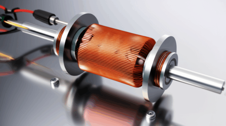
The stator is the stationary set of copper windings inside a motor, generator, or alternator. The rotor spins past those windings and induces AC voltage. Your regulator/rectifier turns that AC into DC to charge the battery and feed the electrical system. That makes the stator the backbone of charging in motorcycles, ATVs, outboard motors, snowmobiles, small engines, and three phase motors. If the stator windings go open or short to ground you can kiss your charging system goodbye.
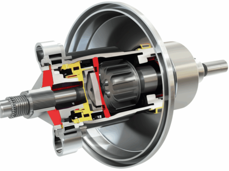
A well-built stator sits on a steel core. The quality of the stator core lamination and the match with the rotor core lamination influence heat, losses, and performance. In industrial gear I also look at the overall motor core laminations and the grade of the electrical steel laminations. Good cores reduce eddy currents and help the windings stay cool. Cooler windings usually live longer.
Symptoms That Point to the Stator
I pay attention when I see these:
- Dead or weak battery after rides or runs
- Dim lights at idle that brighten only a little with revs
- Charging warning lights
- Erratic voltage on the dash or at the battery
- Poor performance on accessories and heated gear
- Burn smell near the engine side cover
- Discolored or burned coils during a visual inspection
To be fair a bad regulator/rectifier can mimic a bad stator. So can a corroded connector or a broken ground. That is why testing the stator windings directly makes sense.
Tools I Keep on the Bench
You do not need a lab. I use:
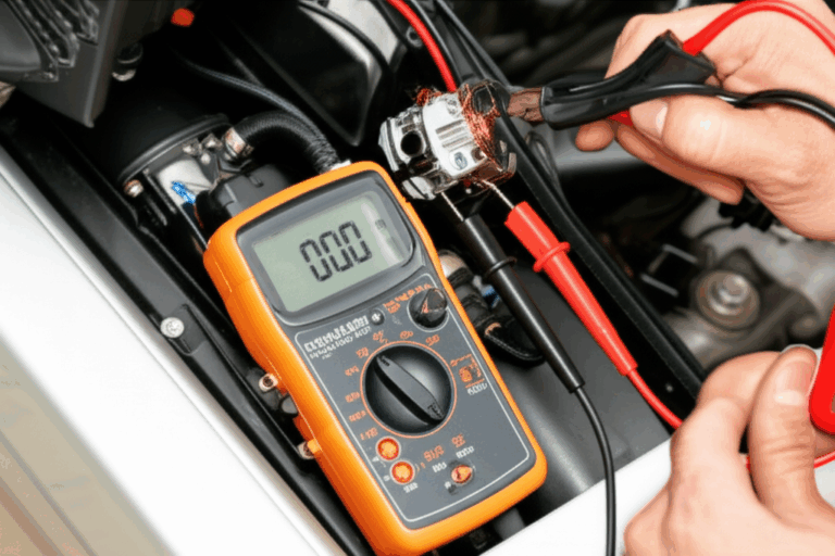
- Digital multimeter (DMM) with Ohms and AC Volts
- Analog multimeter sometimes for quick continuity checks
- Megohmmeter for insulation resistance when I want deeper answers
- Service manual or OEM stator test values and wiring diagrams
- Hand tools to access connectors and covers
- Safety gear like gloves and eye protection
If I suspect advanced issues I may use an oscilloscope for waveform checks or perform inductance or capacitance checks on coils. For most DIY diagnosis a DMM and a bit of patience go a long way.
Safety First Before Any Meter Touches a Lead
This work is straightforward but it still involves electricity and hot engines.
- Disconnect the battery or ignition whenever you do resistance and ground fault tests.
- Let the engine and stator cool before you touch or remove covers.
- Keep fingers clear of spinning parts during running tests.
- Be mindful of fuel vapors and hot exhaust parts.
- Treat a megohmmeter with respect since it applies a high DC test voltage.
I never rush safety steps. They take less time than a trip to the ER.
Step-by-Step Stator Winding Test Procedures
I like a simple flow. Look at it. Measure it. Stress it. Then make a call.
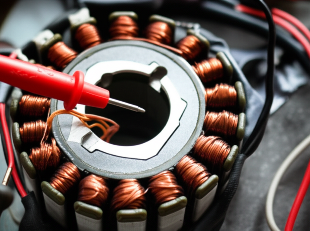
Visual Inspection: The First Line of Defense
I start here because eyes catch what meters miss.
- Look for discoloration, darkened varnish, burn marks, or melted insulation. Heat leaves clues.
- Check for chafed wires, brittle leads, or broken terminals.
- Inspect connectors for corrosion, loose pins, and water intrusion.
- Scan for trapped metal debris and rubbing from the rotor.
- Note any smell of burned varnish. Your nose can be a handy test instrument.
If the coils look roasted I usually prepare for replacement. Testing confirms it but the visual often tells the story.
Resistance Test (Continuity) – Finding Open Circuits
This is your bread and butter check. It finds open circuits and shows if windings are roughly balanced.
What I set:
- Multimeter on Ohms with low-resistance resolution if possible.
- Battery disconnected and the stator unplugged from the regulator/rectifier.
How I identify wires:
- Many motorcycle stators use three yellow leads for a three phase setup.
- Some designs use white, black, or color-coded pairs. Your service manual shows the diagram.
Procedure for three phase stators:
- Measure phase to phase: A-B, B-C, and C-A.
- Expect low resistance and similar readings across all three. Values often land in the 0.1 to 1.0 ohm range though you must verify OEM specifications.
Procedure for single-phase or magneto designs:
- Measure winding to winding as shown in the service manual.
- Compare against the stator resistance values chart for your model if you have one.
How I read the numbers:
- OL or Infinity means no continuity which signals an open circuit. That phase is broken internally.
- Near zero or a significant deviation from spec can point to a partial short or a miswired coil.
- All three readings should be very close to one another on a three phase stator. A standout oddball reading is a red flag.
Pro tip:
- Zero your meter leads first. Touch the probes together and note the reading then subtract that from your measurement if your meter does not auto-compensate.
Ground Fault Test – Finding Shorts to Ground
Shorts to ground crush charging systems. This test takes seconds.
What I set:
- Multimeter on Ohms or continuity.
Procedure:
- Put one probe on a stator lead.
- Put the other on a clean engine ground or the stator core.
- Repeat for every stator lead.
How I read the numbers:
- You want OL or Infinity which means no continuity to ground.
- Any measurable ohms or a beep means a short to ground. The insulation has broken down or the coil is touching metal where it should not.
If the resistance test passes and the ground fault test fails I call the stator bad. No gray area here.
Insulation Resistance Test (Megohmmeter)
When I want to be thorough I use a megohmmeter. It looks for weak insulation that a low-voltage DMM cannot stress.
When I use it:
- After a bike sat in rain or a boat lived in a salty environment.
- When resistance tests look fine yet output still seems low.
- On industrial motors or generators as part of preventative maintenance.
Procedure in short:
- Disconnect the stator. Connect the megger between a stator lead and ground.
- Apply the manufacturer-recommended test voltage for the insulation class. Many small machines use 250 to 500 VDC test levels though you should follow OEM guidance.
- Read the insulation resistance in megaohms.
How I interpret:
- Greater than 2 MΩ is a common minimum for small machines. Many good units read well above 100 MΩ when dry and healthy.
- Anything below 1 to 2 MΩ gets my attention. If the OEM gives a specific minimum I use that.
Moisture can drag readings down. I have dried out stators with gentle heat and retested. If values bounce back and hold the unit might be serviceable. If not I do not gamble.
AC Output Voltage Test (Engine Running)
I saved many hours with this check because it proves the stator actually produces power. A winding can pass ohms tests yet sag under load. I test output before I order parts.
What I set:
- Multimeter on AC Volts.
- Stator unplugged from the regulator/rectifier. I probe the stator side of the connector.
Procedure for three phase stators:
- Measure phase to phase: A-B, B-C, and C-A.
- Take readings at idle and around 3,000 to 5,000 RPM depending on the engine.
Expected results:
- Many motorcycle and small engine stators show roughly 20 to 70 VAC per 1,000 RPM per phase. Check your service manual for OEM stator test values.
- All phases should be close to one another. An unbalanced phase points to a winding issue or rotor problem.
What low or erratic output means:
- Weak permanent magnets in the rotor can cause low voltage.
- Internal winding shorts or partial opens drag output down.
- Check for a loose or damaged rotor key on some engines.
If AC output looks solid across phases and RPM then I move on to the regulator/rectifier and the battery.
Interpreting Your Results and Next Steps
Here is how I call it after those tests.
A good stator usually shows:
- Low and consistent phase-to-phase resistance within spec
- OL to ground on every lead
- Strong and balanced AC output at idle and at higher RPM
- Clean coils with no burn marks or insulation damage
A bad stator usually shows:
- OL between phases during the resistance test which means an open circuit
- Any continuity to ground which means a short to ground
- Resistance values that are far outside the OEM range which hints at winding damage or partial shorts
- Low or unbalanced AC output that follows the same weak phase every time
If the stator passes yet charging still fails I check:
- Regulator/rectifier function and diode behavior
- Battery state of health and capacity not just voltage
- Wiring harness continuity, corroded connectors, and grounds
- On some bikes the crank position or field control systems if used
I keep notes as I test. A simple stator test report with readings at each RPM and phase pays off when you need to compare after a repair.
Real-World Case Study: The “Dead Battery” Mystery
A rider came in with a motorcycle that killed the battery every week. They had already tried a new battery. They also swapped in a used regulator and nothing changed. I unplugged the stator and did a quick resistance test across the three yellow wires. Two pairs measured around 0.5 ohms. The third pair flashed OL. That is an open circuit in one phase. The ground fault test showed OL on all leads so no ground short.
We replaced the stator with an OEM unit. After that I verified AC output at idle and at 4,000 RPM. All three phases delivered balanced voltage in the expected range. The charging issue vanished. The lesson stuck. A 60 second continuity test can pinpoint a complex charging failure.
Common Questions I Hear About Stator Testing
What are acceptable stator resistance readings?
- It depends on the machine. Many sit between 0.1 and 1.0 ohm per phase on small motorcycle style stators. Always check the service manual or an OEM resistance chart.
Can I test a stator without the engine running?
- Yes. The resistance and ground fault checks are done with the engine off and the battery disconnected.
How do I test individual stator coils?
- Some magnetos let you probe coil pairs separately if the leads are accessible. Follow the wiring diagram and compare against OEM coil resistance specs.
How do temperature and age affect readings?
- Copper resistance rises with temperature. A hot stator will read slightly higher ohms than a cold one. Age and thermal cycles degrade insulating varnish which lowers insulation resistance.
Is a megohmmeter necessary?
- Not for every job. It helps diagnose borderline insulation and moisture problems. I use it when I need a deeper look or I am testing a generator or motor for long-term reliability.
What about advanced diagnostics like surge tests or partial discharge?
- Surge testing and partial discharge detection are advanced shop tests. They help spot turn-to-turn shorts that basic DMM tests may miss. They are rarely needed for DIY motorcycle stator testing.
Can I test with an oscilloscope?
- You can. A scope shows AC waveform symmetry and ripple. I use it when chasing intermittent faults or when the multimeter readings do not agree with symptoms.
What else fails in a charging system?
- Regulator/rectifier units fail often. Batteries age out or get sulfated. Connectors corrode and build resistance which starves charging current. Never skip the simple wiring checks.
Preventing Stator Failure: What Works for Me
A little prevention saves stators.
- Keep connectors clean and dry. Moisture and contamination attack insulation and copper.
- Make sure grounds are tight and clean. Poor grounds build heat.
- Maintain battery health. A failing battery can overload the stator and regulator.
- Do not overload the electrical system with accessories that exceed the alternator’s capacity.
- Keep engine cooling in good shape. Heat kills windings and varnish.
- Inspect wiring after off-road rides or heavy vibration. Mechanical stress causes open circuits and chafing.
For industrial motors and generators I also watch the core and lamination quality. Efficient cores run cooler so the windings live longer. Construction details like lamination stacking and material grade matter more than most people think.
Useful Ranges, Specs, and What Affects Them
Here is how I summarize the key tests without a fancy table.
Visual inspection
- Good: Clean windings with intact varnish and no discoloration.
- Bad: Burn marks, melted spots, frayed leads, rubbed-through insulation.
Resistance test (Ohms)
- Good: Low and consistent ohms across phases. Often 0.1 to 1.0 ohm for many small stators. Verify OEM specs.
- Bad: OL means an open circuit. A value way higher or lower than spec suggests internal shorts or damage.
Ground fault test (Ohms)
- Good: OL between every stator lead and ground.
- Bad: Any continuity to ground points to insulation breakdown.
Insulation resistance test (Megohmmeter)
- Good: More than 2 MΩ with many healthy units well above 100 MΩ.
- Bad: Less than 1 to 2 MΩ or below the manufacturer’s minimum.
AC output test (VAC)
- Good: Balanced voltage across all phases that rises with RPM. Many show 20 to 70 VAC per 1,000 RPM.
- Bad: Low, erratic, or unbalanced readings. The weak phase often repeats in every pairing that includes that phase.
Common failure causes I see and the rough share
- Thermal stress or overheating: 30 to 50 percent
- Vibration and mechanical stress: 15 to 25 percent
- Moisture and contamination: 10 to 20 percent
- Manufacturing defects: 5 to 10 percent
- Age and wear: the rest
Temperature effects on resistance
- Copper heats up and resistance rises. Cold readings will sit slightly lower than hot readings. Compare apples to apples when you can.
A Practical Walkthrough for Different Machines
Motorcycles and ATVs
- Most use three yellow stator leads for a three phase alternator.
- Idle output might be modest. Rev the engine to the RPM the manual specifies for the test.
- Watch for reg/rec failures that cook the stator. If you replace one you often replace the other.
Outboard motors and snowmobiles
- Water intrusion and corrosion cause many issues. Dry and clean the connectors and reseal.
- Magneto stator tests often involve single or dual windings for ignition and charging. Follow the diagram closely.
Small engines and generators
- Many small engines have a simple charging coil and sometimes a lighting coil.
- Generator stators can be more robust but still benefit from megger tests during maintenance.
Three phase motor stators in industrial settings
- Follow lockout/tagout procedures.
- Use a megger as part of routine inspections.
- If you suspect turn-to-turn shorts consider a surge test. A basic DMM cannot see those.
Why Construction Quality Matters
I have pulled stators that looked fine on the outside yet ran hot from day one. In many of those cases the core and lamination stack told the story. Better laminations cut eddy current losses which means less heat in the windings. Less heat usually means fewer open circuits and fewer shorts to ground over time. When you shop for replacements pay attention to the build and materials not just the price.
A Simple Diagnostic Flow You Can Follow
- Visual inspection for burns and damage
- Resistance test across phases or coils
- Ground fault test to engine ground
- Megohmmeter test if moisture or insulation issues are suspected
- AC output test at idle and at the specified RPM
- If stator passes move to regulator/rectifier, battery, and wiring
You will notice this mirrors the “look, measure, stress” approach. It keeps you from skipping a simple step.
Little Things That Make the Job Easier
- Use back-probe pins on sealed connectors to avoid damage.
- Photograph wire routing before you pull parts. Reassembly gets easier.
- Label phases A, B, and C with tape while testing. Avoid mix-ups.
- Write down every reading. Patterns jump out when numbers sit side by side.
- If your meter struggles to measure low ohms use the relative or zero function. Or use a 4-wire low-ohm adapter if you have one.
When Replacement Is the Right Call
Some failures are not worth chasing. If you have:
- An open circuit between phases
- Any continuity to ground
- AC output that stays low or unbalanced after ruling out the rotor
Replace the stator. Repairing windings on small units rarely pays off unless you have a rewind shop and a sentimental attachment. I would rather install a quality unit with solid laminations and good varnish impregnation than patch a compromised coil.
A Note on Rotors and Magnets
Do not forget the rotor. Demagnetized or cracked magnets kill output even when the stator looks perfect. Check for physical damage and proper keying on the shaft. If output voltage is low across all phases and rises less than expected with RPM the rotor might be the culprit. A matched stator and rotor set with correct air gap saves headaches.
Quick Reference: Names and Terms You May See
Manufacturers and techs use different labels for similar tests. Here is how I map them in my head.
- Continuity test stator equals resistance test across windings
- Ground test stator equals check for shorts to ground
- Stator coil testing equals phase-to-phase and coil integrity checks
- DC resistance test stator equals ohmmeter check on the coils
- AC output test stator equals engine running voltage check
- Insulation resistance test equals megohmmeter or megger test
- Phase-to-phase resistance equals A-B, B-C, C-A readings
- Phase-to-ground resistance equals each lead to ground check
These all tell pieces of the same story. Taken together they give you a full picture of stator health.
Troubleshooting Beyond the Stator
If the stator checks out look at:
- Regulator/rectifier: Test diodes and regulation function. Many service manuals provide simple tests.
- Battery: Load test it. A battery can show 12.7V at rest and still fail under load.
- Wiring and connectors: Look for voltage drops and hot spots. High resistance joints rob charging current.
- Grounds: Clean and tighten. A poor ground can make a good system look bad.
I never assume a new part is good. I always test.
Final Thoughts: Confidence Beats Guesswork
Testing stator windings does not require black magic. You need a plan, a multimeter, and a steady hand. Start with a visual inspection. Do the resistance and ground fault checks. Use a megohmmeter if you suspect insulation issues. Prove output with the AC voltage test. Then decide.
Once you run this playbook a few times you will spot failures fast. You will also avoid replacing parts that still have plenty of life left. That is money saved and time you can spend on the road, on the water, or on the job.
If you want one last piece of advice here it is. Write down your readings and keep them with your service manual. You build your own stator diagnostics flowchart over time. It becomes your cheat sheet for every machine you touch.