How to Test Stator Voltage (AC & Resistance): A Step-by-Step Guide for Troubleshooting Your Charging System
Table of Contents
- Introduction: Why Your Stator Matters
- Outline of This Guide
- What Is a Stator and How Does It Work?
- What Are the Signs of a Bad Stator?
- What Tools Do You Need to Test a Stator?
- How Do You Stay Safe While Testing?
- How Do You Test Stator AC Voltage Step by Step?
- How Do You Test Stator Resistance and Continuity?
- What Do Your Multimeter Readings Mean?
- What If the Stator Passes but the Battery Still Does Not Charge?
- Do Brand Examples Help? Yes—Here’s How
- Can a Visual Check Save You Time?
- What Causes Stator Failure and How Do You Prevent It?
- What About Single Phase and Three Phase Stators?
- How Much Does Stator Replacement Cost and Who Should Do It?
- Quick Diagnostic Flow You Can Trust
- Common Values and What They Tell You (Table)
- Company Note: Why Core Quality Matters
- FAQ (Optional)
- Key Takeaways
Your bike will not charge. Your ATV dies at night. Your boat cranks but the battery drains. I have felt the same pain. In this guide I show you how to test stator voltage and resistance with a simple digital multimeter. You will learn safe steps. You will see what numbers mean. You will fix the problem or rule out the stator fast.
Outline of This Guide
- What a stator does in your charging system
- Bad stator symptoms you can trust
- Tools you need for diy stator test
- Safety moves before any test
- Engine running ac voltage test
- Engine off resistance and continuity test
- How to interpret high, low, or uneven readings
- Next steps if the stator is good
- Brand tips: Honda, Yamaha, Harley, Suzuki, Kawasaki, Briggs & Stratton, Kohler, Mercury Marine
- Visual inspection and common failure causes
- Single phase vs three phase stator testing
- Cost, parts, and pro help
- A simple diagnostic flow chart stator plan
- A data table with typical values
- Why core lamination quality matters to you
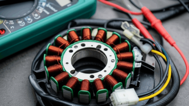
What Is a Stator and How Does It Work?
A stator is the fixed part of your alternator or magneto. It has copper windings. The rotor or flywheel spins around it. The magnets on the rotor pass the windings. That motion makes AC voltage. Your rectifier and voltage regulator turn that AC into steady DC voltage to charge the battery and run the electrical system.
In simple words. The stator makes AC power. The rectifier changes it to DC. The voltage regulator holds the DC to a safe level. The charging system needs the stator, the rectifier regulator, and the battery to work as a team. If the stator fails you get a no charging problem. If the rectifier regulator fails you also get a battery not charging condition. You need to test both parts. Today we focus on how to check stator output.
I use this on motorcycles, ATVs, boats, and small engines. You can use it on an alternator stator or a flywheel magneto stator. You can test a single phase stator or a three phase stator. You can test a permanent magnet stator or an electromagnetic stator. The steps stay clear.
What Are the Signs of a Bad Stator?
You can spot bad stator symptoms fast. Here is what I look for in my shop.
- Dim headlights at idle. They may brighten at high rpm. That hints at weak AC voltage test stator results.
- Battery draining fast. You ride or boat then the battery loses charge. That points to low charging system output.
- Engine dies at high rpm. A failing ignition stator can cause weak spark troubleshooting issues.
- No charging problem. You see a red battery light or DC voltage at the battery stays low.
- Electrical system check shows low charging system diagnostics numbers.
- Discolored stator windings. Heat damaged stator windings look dark. Melted epoxy also hints at failure.
- Odd stator voltage readings. High voltage stator readings at no load then poor DC to battery can mean bad rectifier.
- Weak or no spark on some engines that use a magneto stator for ignition.
These are common stator failure causes we see: heat, vibration, age, and sometimes a faulty regulator that overloads the stator. Sometimes magnets chip on the flywheel. Sometimes oil leaks or heat cook the windings. You can fix this with good testing and proven parts.
What Tools Do You Need to Test a Stator?
You do not need fancy gear. You need solid basics.
- A digital multimeter (DMM) with AC Voltage and Ohms settings. Learn how to use a digital multimeter first.
- Test leads with good clips. Clean tips help.
- Basic hand tools. Screwdrivers and wrenches to access connectors or covers.
- A shop manual. It lists stator specifications. It shows the proper stator wiring diagram and stator wire colors.
- Safety gear. Gloves and eye protection.
- Optional: a peak voltage adapter (PVA) for some ignition stator tests.
You also want clear space. Keep parts and tools in a tray. Keep kids and pets away. Good prep makes a safe stator testing job go smooth.
How Do You Stay Safe While Testing?
Safety first. AC power and spinning parts can bite. I learned to slow down and follow a simple plan.
- Disconnect the battery negative terminal before you unplug anything. You can reconnect it later for running tests.
- Know when to test with engine off vs engine running tests. Resistance tests happen with the engine off. Voltage tests happen with the engine running.
- Beware of hot engine parts. Let it cool if needed. Watch for belts or the flywheel. Loose clothes can snag.
- Proper multimeter handling matters. Set the range right. Hold the insulated parts of the leads. Do not touch live metal with bare hands.
- Keep wires and tools clear of the rotor. Keep hair clear too.
This is safe stator testing when you follow the steps. Take your time. You will feel calm and in control.
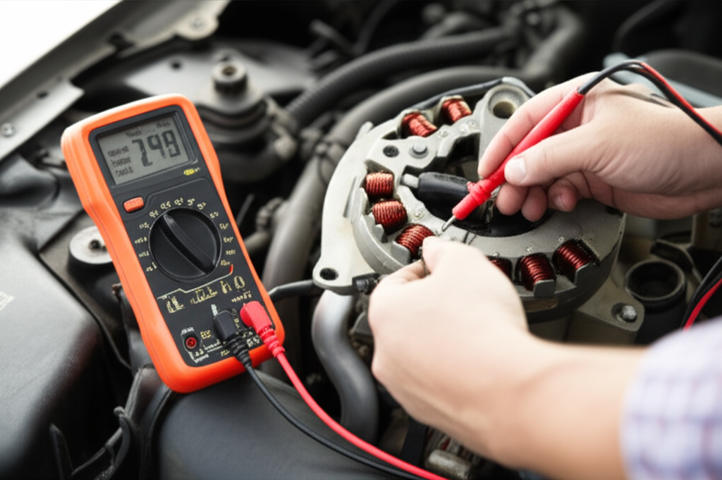
How Do You Test Stator AC Voltage Step by Step?
This is the engine running ac test. It tells you how to measure stator voltage under no load. It is the heart of how to check stator output.
Preparation:
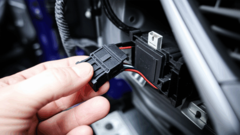
- Find the stator wires. You will see two or three yellow or white wires that go from the stator to the rectifier regulator. This is your stator to rectifier plug.
- Disconnect the plug to isolate the stator from the rectifier regulator. Now the stator is under no load.
Set up your multimeter:
- Set the DMM to AC Voltage. Look for V~ or VAC. Pick a range above what you expect. 200V AC works on most bikes and small engines.
Run the test:
- Start the engine. Let it warm up. Idle steady.
- Place test leads on any two stator output wires. This is the phase to phase voltage test. Note the reading at idle.
- Raise engine rpm to the spec in your manual. Many call for 3000 to 5000 RPM. Note the voltage readings stator shows at each rpm.
- For three phase stator tests you repeat for all wire pairs. Example: Yellow1–Yellow2. Yellow1–Yellow3. Yellow2–Yellow3.
- For a single phase stator test you have two wires. Just test across those two.
What do you expect? Many permanent magnet stators put out about 20 to 25 VAC per 1000 RPM. I often see 15 to 30 VAC at idle. Then 35 to 70 VAC at 3000 to 5000 RPM. Your shop manual has the final word. Always check your model.
How Do You Test Stator Resistance and Continuity?
This is the engine off stator test. It checks the winding resistance and checks for shorts to ground.
Preparation:
- Engine off. Key off. Unplug the stator from the rectifier regulator.
Set up your multimeter:
- Set DMM to Ohms Ω. Pick the lowest range like 200Ω if your meter is not auto range.
Winding resistance test:
- Touch the leads together to zero your meter if needed.
- Probe any two stator output wires. Note the ohms reading stator shows.
- Repeat for all pairs on a three phase stator.
Continuity to ground test:
- Place one lead on clean engine ground. A bare metal bolt on the engine case works well.
- Touch the other lead to each stator output wire one at a time.
- You want no continuity to ground. Your meter should show OL or Infinite Ω.
What is normal? Stator coil resistance is very low. Many show 0.1 to 1.0 Ohm. All phases should match closely. If one reads much higher you have damage. If one reads zero you may have a shorted winding. If one reads open circuit you likely have a broken winding.
What Do Your Multimeter Readings Mean?
Numbers tell a story. Learn the plot and you win.
Normal AC voltage:
- All phase to phase readings look close. They rise with RPM. They match the manual spec. This shows a good stator.
Low AC voltage:
- All readings sit low. This can mean weak magnets on the flywheel magneto. It can also be a partial winding short. Check visual signs and ohms to confirm.
Zero AC on one pair:
- This hints at an open circuit stator winding. The resistance test will show OL on that pair.
Uneven readings between phases:
- This can show a stator winding short or a damaged coil. Replace the stator.
High voltage at no load:
- Some readings look high when the plug is off load. That can be normal. The rectifier regulator will pull it down when connected. Always test per the manual.
Resistance results:
- Normal: very low ohms. All phases match. No continuity to ground.
- High or infinite ohms: open circuit. Broken wire or heat damage.
- Zero or very low beyond spec: short circuit between windings.
- Any continuity to ground: insulation failed. The winding is shorted to the engine case.
What If the Stator Passes but the Battery Still Does Not Charge?
Problem:
- Stator passed the ac voltage test. Stator passed the resistance test and the continuity to ground test. Yet the battery not charging issue stays.
Agitate:
- You buy a new battery. It still dies. You ride home in the dark with dim lights. You jump it for the third time this week. This is not fun.
Solution:
- Test the rectifier regulator next. This is the test rectifier regulator step. The rectifier turns AC to DC. The regulator holds the DC voltage near 14.0V on most bikes. Check DC Voltage at the battery with the engine running. You should see about 13.5V to 14.7V at 3000 RPM. If DC stays low then the rectifier regulator or the wiring harness or bad connectors or fuses can be the cause. Check the wiring. Check the charging system components. Fix the simple things first.
In short. A stator passed result shifts your focus. Now you test the rectifier regulator. Then the battery. Then the load. A clear diagnostic flow saves time and money.
Do Brand Examples Help? Yes—Here’s How
Let me share quick tips on common brands. Always use the shop manual for exact stator specifications.
- Honda stator test: Many Honda bikes use three yellow wires. Expect 20–25 VAC per 1000 RPM. Check the manual for your model.
- Yamaha stator test: Similar to Honda. Some models use a peak voltage adapter for ignition stator leads. Follow the magneto test procedure if you test spark.
- Harley stator test: Harleys often use a two wire single phase stator. You will see AC around 16–20 VAC per 1000 RPM.
- Suzuki stator test and Kawasaki stator test: Very similar to Honda and Yamaha. Focus on phase to phase voltage and no ground faults.
- Briggs and Stratton stator test and Kohler stator test: These small engines may use half wave rectifier stator or full wave rectifier stator setups. Some only charge. Some also feed lights. Check the wiring colors. Check resistance to engine ground.
- Mercury outboard stator test: Many outboards use a magneto stator for ignition and a separate charge coil. Use a PVA for peak voltage tests on ignition leads. Follow the Mercury Marine manual to the letter.
I keep notes on each platform. It pays off. Little things like multimeter lead placement and the right rpm make all the difference.
Can a Visual Check Save You Time?
Yes. I always do a visual inspection stator check before I grab the meter.
Look for:
- Burnt or discolored stator windings. Black or brown windings show heat damaged stator coils.
- Melted epoxy or plastic. That means overheating.
- Damaged wire insulation. Abrasion from the rotor or rotor core can cut the enamel.
- Chipped or loose magnets on the flywheel. That can kill output. It can also shred windings.
Also check connectors. Look for green corrosion. Look for heat marks. Replace bad terminals. A clean terminal and a solid wiring harness fix many no charge issues without parts.
What Causes Stator Failure and How Do You Prevent It?
Common causes:
- Overheating due to high current draw or a failed voltage regulator. The stator cooks and the insulation breaks down. That leads to a stator winding short or a stator to ground test fail.
- Vibration. It rubs the windings. It cracks solder joints.
- Age and mileage. Heat cycles and time break down insulation.
- Poor parts. Low grade wire or weak stator core damage the system over time.
How to prevent:
- Keep the cooling system and oil system in good shape. Heat kills windings.
- Fix bad grounds. High resistance makes more heat.
- Replace bad rectifier regulators before they cook the stator.
- Use quality parts. Good stator core lamination and solid windings run cooler and last longer. The same is true for a matching rotor core lamination with true magnet spacing.
I have seen cheap parts fail fast. I now choose parts with good metal and sound epoxy. My comebacks dropped.
What About Single Phase and Three Phase Stators?
Single phase stator:
- Two wires. You test across them. Expect rising AC voltage with rpm. Many older bikes and some Harleys use this.
Three phase stator:
- Three wires. Often yellow. You test all pairs. All three phase to phase voltage readings should match within a small margin. If one pair is off you have a problem.
Full wave rectifier stator vs half wave rectifier stator:
- Full wave uses all of the AC waveform. It gives better DC output. Most modern bikes use it.
- Half wave uses only half the cycle. It gives less DC. Some small engines use this and dim lights are common at idle.
Permanent magnet stator vs electromagnetic stator:
- Most bikes use permanent magnets in the flywheel. Output rises with rpm.
- Some systems use a field coil rotor. You control output with current. Diagnosis differs. Always check the manual.
How Much Does Stator Replacement Cost and Who Should Do It?
Parts cost varies. A small engine stator can cost less than a couple hundred dollars. A big motorcycle stator can cost more. A marine stator may cost even more. Labor adds time for cover removal. You also need a new gasket. Always check your model.
DIY or pro?
- If you can test and read a meter you can do a diy stator test. If you can follow the shop manual you can swap a stator on many bikes. Watch the flywheel magnets. Use a torque wrench. Replace the gasket. Clean the mating surfaces. Set wire routing to avoid rub.
- If you feel unsure hire a pro. A pro can test the regulator, the diodes in the rectifier, and the rest of the electrical system. A pro can also find a short circuit or an open circuit in the harness fast.
When you install new parts use quality. I favor tight motor core laminations and good varnish. I also like clean electrical steel laminations for cool running. Good core stacks reduce eddy losses. That keeps heat down and life up.
Quick Diagnostic Flow You Can Trust
Here is a simple diagnostic flow chart stator plan you can follow:
- Step 1: Battery check. Charge it and load test it. Fix the battery first.
- Step 2: DC Voltage check at battery with engine running. 13.5–14.7V is the target for many bikes. If DC is low move to Step 3.
- Step 3: Unplug stator from rectifier regulator. Do the engine running AC voltage test phase to phase. If AC is in spec go to Step 4. If AC is low replace stator.
- Step 4: Engine off. Do the resistance test phase to phase and the continuity to ground test. If both pass the stator is good. Go to Step 5.
- Step 5: Test rectifier regulator. Check diodes with a meter if your manual shows the method. Replace if bad.
- Step 6: Check fuses, connectors, and the wiring harness for breaks or shorts.
- Step 7: Recheck the charging system with DC Voltage at RPM.
This flow gives you a solid charging system overview. It helps you avoid bad guesses.
Common Values and What They Tell You (Table)
These ranges are common on many systems. Always check your model manual. Numbers vary with design.
| Test Type / Metric | Typical Expected Range / Value | Indication of Good Stator | Indication of Bad Stator | Common Cause / Implication |
|---|---|---|---|---|
| AC Voltage Output (Phase-to-Phase) | Idle: 15–30 VAC. 3000–5000 RPM: 35–70 VAC. Often 20–25 VAC per 1000 RPM | All phases read close. Voltage rises with RPM. Values match spec | Low across all. Zero on one pair. Uneven between pairs | Open or shorted winding. Damaged insulation. Magnet loss on flywheel magneto |
| Winding Resistance (Phase-to-Phase) | Very low: 0.1–1.0 Ω (check manual) | Low and even across phases | OL/Infinite Ω (open). Much higher than spec. Zero or far lower than spec | Broken wire from heat. Partial short from melted enamel. Poor connection |
| Continuity to Ground | No continuity (OL/Infinite Ω) | No reading to engine ground on any stator wire | Any Ω reading shows a short to ground | Insulation failed. Coil touches engine case |
| Visual Inspection | Clean copper. No dark spots. Intact epoxy and insulation | Windings look bright. No rub marks | Burnt or brown coils. Melted epoxy. Chipped magnets | Overheating from bad regulator. Vibration. Physical damage |
Company Note: Why Core Quality Matters
The stator core and rotor core shape how the magnetic field flows. Good cores cut losses. Poor cores waste energy as heat. That extra heat eats the varnish on the windings. Then you get a short.
When you buy or build motors or generators use quality cores. You want smooth steel edges. You want tight stacks. You want right-grade silicon steel. This helps your charging system live a long life. You can learn about stator and rotor cores here:
- How precise stator core lamination supports stable output.
- Why a balanced rotor core lamination keeps vibration down.
- How clean motor core laminations reduce heat.
- Why premium electrical steel laminations matter in every coil-based device.
Better cores. Cooler windings. Stronger charge. Simple as that.
FAQ (Optional)
Q: What voltage should a stator put out?
A: Many permanent magnet stators show about 20–25 VAC per 1000 RPM. I often see 15–30 VAC at idle and 35–70 VAC at 3000–5000 RPM. Always check the manual for your model.
Q: How many ohms should a stator be?
A: Very low. Many read 0.1 to 1.0 Ohm phase to phase. All phases should be close. Use the manual spec.
Q: Do I need a peak voltage adapter?
A: For charging checks you do not. For some ignition stator tests you do. Follow the magneto test procedure in your manual.
Q: Can I test the stator with the engine off only?
A: No. You need the engine running ac test to check output. You also need engine off resistance and ground tests. You need both.
Q: What if I see continuity to ground?
A: The stator is shorted to the engine case. Replace the stator.
Key Takeaways
- The stator makes AC. The rectifier and regulator turn it to DC to charge the battery.
- Bad stator symptoms include dim lights, fast battery drain, and no charge at rpm.
- Use a DMM. Test AC Voltage phase to phase with the engine running. Then test resistance and continuity to ground with the engine off.
- Normal AC rises with rpm. Normal resistance is very low. No continuity to ground is allowed.
- If the stator passes you test the rectifier regulator, the wiring harness, fuses, and battery.
- Keep an eye on heat and vibration. They cause most failures.
- Quality core laminations help the charging system last longer.
- Follow the shop manual for your bike, ATV, boat, or small engine.
- Stay safe. Disconnect the battery before unplugging. Watch hot parts. Use proper multimeter handling.
- Use this simple diagnostic flow to save time and money.
References:
- Honda Motorcycle Service Manuals. Charging system and stator testing sections.
- Yamaha Service Manuals. Magneto and alternator testing chapters.
- Harley-Davidson Electrical Diagnostic Manuals. Stator and regulator tests.
- Suzuki and Kawasaki Factory Service Manuals. Charging system diagnostics.
- Briggs & Stratton and Kohler Small Engine Manuals. Charging coil and rectifier tests.
- Mercury Marine Outboard Manuals. Stator and ignition peak voltage procedures.
- Standard electrical principles for AC and DC measurement with digital multimeters.