How to Test Stator Resistance: A Comprehensive Diagnostic Guide
Short on charge. Lights flicker. Engine stumbles. If you’ve seen this show before, your stator may be the star of the problem. In this guide I’ll walk you through simple steps to test stator resistance with a digital multimeter. You’ll learn what the readings mean, how to fix issues, and how to prevent the same trouble later. I’ll also show you how better parts and quality laminations help your stator last longer with less heat and less loss.
Table of Contents
- Why bother testing stator resistance?
- What does a stator do and why should you care?
- What are the common signs of a bad stator?
- What tools do you need for a safe stator testing procedure?
- How do you stay safe while testing?
- How do you find and access the stator wires?
- How do you set and check your digital multimeter?
- How do you test phase-to-phase resistance?
- How do you test phase-to-ground insulation resistance?
- How do you compare readings with the service manual?
- What do your readings mean in plain English?
- What causes stator failure and how do you prevent it?
- Should you test AC output too?
- Quick reference tables
- FAQs
- A better fix: build on strong cores and laminations
- Key takeaways
Why bother testing stator resistance?
Problem: The battery won’t charge. The dash looks dim. The engine runs rough. You feel stuck.
Agitate: You jump the engine. It starts then dies at the next stop. You swap the voltage regulator/rectifier. No luck. You burn time, money, and nerves.
Solution: Test the stator first. A quick winding resistance test and a continuity test stator with a multimeter can save the day. You’ll spot an open circuit stator, a short circuit stator, or a ground fault stator fast. You can use the right multimeter settings for stator, check a stator resistance chart, and compare to manufacturer specs stator. This simple check works on a motorcycle stator, an alternator stator in an automotive system, a generator stator, or any electric motor stator in a small engine, HVAC motor, pump motor, appliance motor, water pump motor, electric bicycle, or scooter.
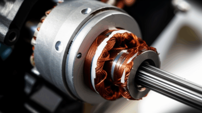
What does a stator do and why should you care?
The stator is the fixed part of an alternator or generator. It holds the winding (coil). The rotor spins by the flywheel, the magnet, or the engine. Together they make AC voltage to power the charging system and sometimes the ignition system. In cars the ECU (Engine Control Unit) depends on a healthy charging system. In bikes the stator feeds the voltage regulator/rectifier which turns AC to DC voltage.
Without a strong stator you get weak power. You may see battery not charging, no charge, or overcharging battery test fails. You might see dim lights at idle, flickering lights driving, weak spark diagnosis issues, or engine misfire related to stator. Good stator health keeps your electrical system steady and your trips easy.
What are the common signs of a bad stator?
- The battery shows low voltage after a ride. You charge it but it drops again.
- Headlights go dim or flicker. The dash pulses at low RPM (Revolutions Per Minute).
- The engine cranks but won’t start. Or it starts and stalls. You get rough running.
- You smell hot windings. You hear odd noises near the lamination stack.
These are classic bad stator symptoms. They point to high phase to phase resistance, low phase to phase resistance, or a phase to ground resistance that isn’t infinite. They can also point to a weak voltage regulator/rectifier test result or a bad wiring harness, fuse, or circuit breaker. But start with the stator. It’s fast and clear.
What tools do you need for a safe stator testing procedure?
You don’t need a lab. You need a few basics.
- A good Digital Multimeter (DMM) with a clear ohmmeter mode. Make sure you know how to use a digital multimeter. Use clean test leads. Check scale and calibration of multimeter if you can.
- Your vehicle/machine service manual. It shows resistance specifications, stator wiring diagram, and stator output specifications. It also shows testing three phase motor stator and testing single phase motor stator steps.
- Safety gear: insulated gloves and eye protection.
- Cleaning tools: a small brush or sandpaper to clean a ground point.
- If you have one, a megohmmeter (insulation tester) helps with deeper insulation resistance test. Not required for basic checks.
How do you stay safe while testing?
- Disconnect the battery before you test resistance. This avoids sparks and protects the electrical system.
- Let the engine cool. Hot parts burn you. Heat also changes readings because of temperature effects on resistance. A cool engine gives better data on cold resistance vs hot resistance.
- Work in a dry area. Moisture can cause a false ground fault.
Know the hazards of AC voltage, DC voltage, and spinning parts. Follow basic safe electrical testing rules. Keep the flywheel and rotor still while you probe.
How do you find and access the stator wires?
Look for the wire connector from the stator (component). On a motorcycle you often find a three-wire plug under a side cover for a three-phase stator. A single-phase setup may have two wires. Trace from the alternator or generator case to the plug. Check the wiring diagram in the service manual stator chapter.
Clean the plug. Remove any dirt, oil, or corrosion stator build up. If the plug looks burned, note it. Heat and vibration damage stator plugs. That can cause the very charging system diagnosis headaches you see.
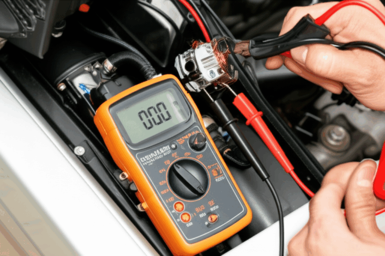
How do you set and check your digital multimeter?
Turn your DMM to the lowest ohms (Ω) range. Short the two probes together. You should see near zero. This checks lead health and any offset. Some meters have a “relative” or zero function. Use it to subtract lead resistance, so your multimeter ohms reading on the stator is more exact.
Make sure the test leads for multimeter fit the connector pins snug. Loose tips cause shaky numbers. If the tips are dull, replace them. Proper multimeter usage matters.
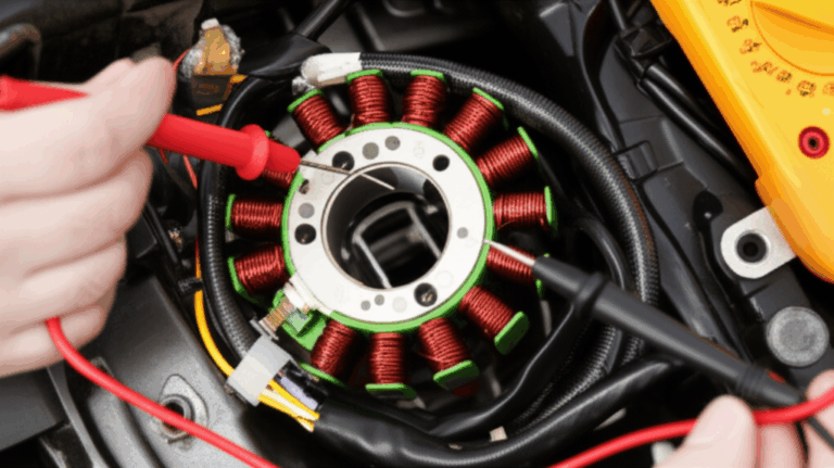
How do you test phase-to-phase resistance?
For a three-phase stator:
- Label the wires A, B, and C. Touch one probe to A and the other to B. Record the phase to phase resistance. Then test B to C. Then C to A. Write them down. Each pair should read low and about the same. Many small motorcycle stator windings read in the 0.1 to 1.0 ohm range. Some generator stator sets read higher. Check the specifications manual stator for your exact resistance values.
For a single-phase stator:
- Touch the probes to the two stator wires. Note the winding resistance test result.
What are you looking for?
- You want low and even numbers on all pairs. Big differences mean trouble. A very high or open line reading shows a break in the stator winding open. A very low or near zero shows a stator winding short.
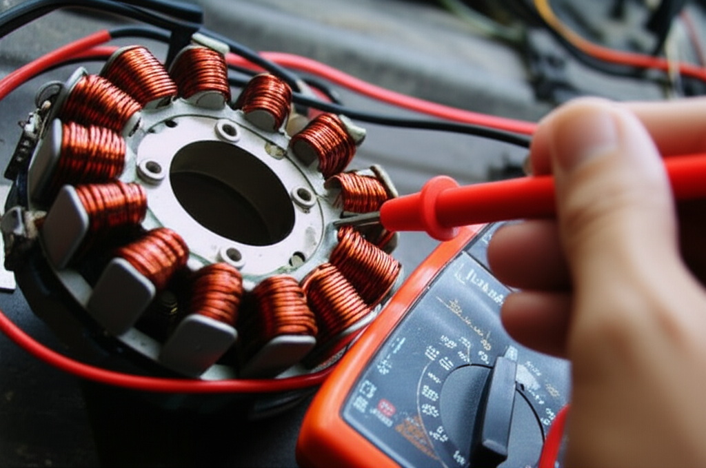
How do you test phase-to-ground insulation resistance?
This is your winding-to-ground or phase to ground resistance test.
- Set your meter to a high ohm range. Touch one probe to a stator wire and the other probe to clean engine ground. A bolt on the case works well. Clean it to bare metal.
- Do this for each stator wire.
What should you see? You should see “OL” or very high ohms. That means no path to ground. Any continuity test stator that shows low ohms to ground means a ground fault stator. That will kill the charging system fast.
If you own a megohmmeter, you can test insulation resistance at a higher test voltage. This finds weak insulation that a normal DMM might miss.
How do you compare readings with the service manual?
Open your service manual or the manufacturer specs stator sheet. Find the acceptable resistance deviation and the exact resistance specifications for your model. Some manuals list temperature effects on resistance and show acceptable tolerances. Note if the test should be done hot or cold.
Match your notes to the table. If your phase-to-phase numbers are low, even, and within the range you win. If one leg reads high you may have an open circuit. If they read low or uneven you may have an inter-winding short. If any leg shows low ohms to ground you have a ground fault.
What do your readings mean in plain English?
- Normal readings: All three pairs read low and close to each other. You see open line to ground. Your stator coil test passes. This looks like a healthy stator.
- Open circuit: One pair reads “OL” where it should read low. This means a broken wire in the coil (winding) or a bad wire connector.
- Short circuit: One or more pairs read lower than spec. You may also see any continuity to ground. This means the winding rubbed through, burned, or touched the lamination or case. The magnetic field test would be weak. You might also see signs like heat damage stator, dark varnish, or smell burnt.
What next?
- If the stator fails resistance tests you replace or repair it. Choose stator repair vs replacement based on cost, time, and your skill. Many riders choose replacement because windings are tight work. If it passes but you still have no charge you should run an AC voltage test stator and a voltage regulator rectifier test. You should also run a voltage drop test stator and an amp draw test stator across the electrical system.
What causes stator failure and how do you prevent it?
- Overheating & electrical overload: High load and poor cooling bake the windings. Bad voltage regulator/rectifier parts can push too much current. Poor lamination quality and tight cores raise inductive loss and heat. Hot copper has higher resistance. As heat rises your motor efficiency testing looks worse.
- Vibration & mechanical stress: Worn bearings stator and rotor rub. Loose parts shake. This can nick enamel and cause an inter-winding short. It can also crack the lamination stack.
- Contamination: Oil, dirt, and moisture invade the case. Corrosion stator follows. This often leads to a ground fault or a weak insulation resistance test.
- Age and wear: Time breaks down varnish. Cycles of heat and cool stress the coil.
Prevention tips:
- Fix loose mounts. Check bearings. Kill vibration at the source.
- Keep the case clean and dry. Replace leaky seals.
- Use quality parts. The quality of the stator core lamination and the accuracy of the lamination stack matter for lower losses and cooler windings.
- Match parts to OEM specs. Cheap parts can overheat the system.
Should you test AC output too?
Yes. Resistance checks tell you about the winding health at rest. They don’t show how the stator performs under spin and load. An AC voltage test stator shows what happens when the rotor turns and the magnetic field cuts the windings.
Basic steps:
- Reconnect the battery. Start the engine. Back probe the three stator wires. Set the DMM to AC voltage.
- Measure A-B, B-C, and C-A at idle and at a higher RPM per the manual. Each pair should be close and rise with RPM.
- If AC output passes but the battery still drains check the rectifier regulator function. Some riders also test flywheel magnet strength if AC is low.
Quick reference tables
Typical motorcycle three‑phase stator checks
| Check | Good Sign | Bad Sign | What It Means |
|---|---|---|---|
| Phase-to-phase resistance | All three pairs low and even (often 0.1–1.0 Ω; follow your manual) | One pair high (OL) or much lower than others | Open or short in windings |
| Phase-to-ground resistance | OL or very high | Any low reading or continuity | Ground fault/insulation failure |
| AC output at idle | Even voltage on all pairs | One pair low | Weak leg or rotor issue |
| AC rise with RPM | Voltage rises smoothly | Little rise | Weak rotor magnets or shorted windings |
Note: Copper changes about 0.39% per °C. So hot windings show a bit higher resistance. That’s why many manuals call for a cool test.
Troubleshooting path
| Symptom | Likely Tests | Next Steps |
|---|---|---|
| Battery not charging | Phase-to-phase, phase-to-ground, AC output | If stator OK test voltage regulator/rectifier and wiring |
| Dim lights at idle | AC output vs RPM | Check idle speed and regulator |
| Engine cranks but no start | Ignition stator test, continuity | Check ECU, DTCs, and coils |
| Overcharging battery | Regulator test | Replace regulator and re-check stator |
FAQs
Q: Can I test a stator without removing it from the engine?
A: Yes. Most DIY stator test steps use the external plug. You only remove it if resistance or AC tests fail and you plan to inspect or replace it.
Q: My multimeter shows “OL” on the ohms scale. What does this mean?
A: “OL” means open line. The DMM sees no path. That’s good for phase to ground checks. It’s bad for phase to phase checks where you expect a small number.
Q: Why do resistance values vary between different engines?
A: Designs differ. A motorcycle, a car alternator, a small engine, and an industrial motor use different stator windings and wire sizes. Always follow your service manual specs.
Q: Is a slightly off resistance reading a sure sign of failure?
A: Not always. Small differences can come from temperature, lead error, or meter range. That’s why you check acceptable resistance deviation in the spec and you test AC output too.
Q: Should I also check the rotor?
A: If AC output is low on all pairs check the rotor and flywheel magnet strength. Poor magnet strength or a damaged rotor core lamination can drop output.
A better fix: build on strong cores and laminations
Here’s a secret many techs learn the hard way. The quality of the steel stack under the windings shapes heat and loss. Tight, precise motor core laminations cut eddy losses. Better laminations mean cooler windings at the same load. Cooler windings last longer. That’s good for your wallet and for uptime.
If you build, repair, or spec motors or alternators consider high grade motor core laminations. For stators pick precise stator core lamination. Ask about core steel. High grade electrical steel laminations reduce core loss and heat. This helps with longevity of stators, prevention of stator failure, and overall charging system stability. If you work on BLDC machines you can also spec a strong bldc stator core from a proven source. Better cores don’t just look nice. They run cooler, hum less, and make diagnostics easier.
Putting it all together with PAS
- Problem: Low charge, rough idle, dim lights, engine not starting troubleshooting. You worry it’s the ECU, wires, or worse.
- Agitate: You replace parts and chase ghosts on online forums stator test and youtube videos stator testing. Time slips. The bike or car still fails. You feel stuck on the side of the road.
- Solution: Run this simple stator testing procedure. Do a winding resistance test, a continuity test, and an insulation resistance test. Then test AC output. Compare with your service manual. If the stator fails replace it with quality parts built on tight laminations. Build on strong cores and you cut heat and stress from day one.
Real world tips and examples
- Example 1: A rider with a motorcycle stator test shows 0.3 Ω on A-B and B-C but 0.05 Ω on C-A. That low number points to a stator winding short. AC output also reads low on C-A. Replacing the stator fixes the charging system.
- Example 2: A small generator stator diagnosis shows good resistance but low AC voltage test on all legs. The fix is a new voltage regulator/rectifier and a check of the flywheel magnet strength.
- Example 3: An automotive alternator stator test passes ohms but fails the amp draw test stator. The wiring harness had a corroded ground near the case. Clean metal, tight bolts, and a fresh fuse solved it.
Extra checks when needed
- If resistance and AC pass but charging is weak check the rectifier regulator function, run a voltage drop test stator across connectors, and inspect the wire connector pins.
- If you see overcharging check the regulator. Overcharge cooks the battery and the winding varnish.
- If the engine misfires under load and the bike uses an ignition stator test path make sure those windings meet spec too.
- For large motors try industrial motor stator test methods and a megohmmeter for deep insulation checks.
- For HVAC motor stator test and appliance motor stator test follow the maker’s electrical specifications and wiring schematics.
Related terms you’ll see in manuals
When you read electrical schematics stator you may see:
- Open circuit and short circuit symbols for failures
- Phase labels like U, V, W or A, B, C
- Ohm’s Law for current, voltage, resistance
- Field windings and armature windings in different machines
- Inductive kickback test notes in ignition circuits
- Diagnostic Trouble Codes (DTCs) logged by the ECU
- References to Aftermarket Parts, Manufacturer (OEM) notes, and Repair Shop advice from a Mechanic or Electrician
Good manuals stress spec ranges, clear test points, and safety. That’s your roadmap.
References
- OEM Service Manual for your exact vehicle or machine model
- Fluke Digital Multimeter User Guide (for safe and accurate readings)
- IEC 60034 Rotating Electrical Machines (general reference for testing methods)
- EASA (Electrical Apparatus Service Association) guidance on winding and insulation checks
- NFPA 70 National Electrical Code for safe electrical work practices
These references help you follow tested methods and use tools the right way.
Simple step-by-step checklist
A quick word on quality cores
The stator and rotor live by the core. Better laminations cut losses, reduce heat, and boost life. Precision stacks lower vibration, keep the magnetic field tight, and hold spec over time. If you design or source parts look for accurate stacks and clean steel. You can learn more by browsing precise electrical steel laminations. Strong cores help every test go right.
Summary: the most important things to remember
- Test resistance first. It’s fast and clear.
- You want low and even phase‑to‑phase readings and OL to ground.
- Compare numbers with your service manual. Don’t guess.
- Test AC output under RPM. Resistance alone is not the full story.
- Fix heat, vibration, and contamination to prevent repeat failures.
- Use quality laminations and parts to cut losses and extend life.
- Safety first. Cool engine, battery disconnected, clean ground points.
- Keep it simple. Measure, compare, decide. Then repair with confidence.