How to Test Stator Output: A Comprehensive DIY Guide
Table of contents
- Why I Test Stators First When a Bike Will Not Charge
- What a Stator Does and Why It Fails
- Symptoms That Point Me to the Stator
- Tools I Actually Use for Stator Testing
- Before You Start: Safety, Wire ID, and Specs
- Step-by-Step Stator Testing
- Preparation and safety first
- Test 1: Stator AC voltage output test (engine running)
- Test 2: Stator winding resistance test (engine off)
- Test 3: Stator ground continuity test (engine off)
- Optional advanced checks: scope patterns and insulation tests
- How I Interpret Results and What I Do Next
- Application Notes: Motorcycles, ATVs, Outboards, and Small Engines
- Visual Inspection Tips and Common Failure Causes
- Common Mistakes I See and How to Avoid Them
- Repair vs Replacement: My Rule of Thumb
- Frequently Asked Questions
- Conclusion: Keep Your Charging System Healthy
Why I Test Stators First When a Bike Will Not Charge
When a motorcycle rolls into my garage with a dead battery I do two things. I charge the battery so I can crank the engine again. Then I reach for my multimeter. Years ago I guessed too much. I replaced batteries that were fine and I replaced regulators that were innocent. Once I learned a fast stator test sequence I started finding the real problem in minutes. You can do the same at home without fancy equipment. You need a digital multimeter and a little patience.
What a Stator Does and Why It Fails
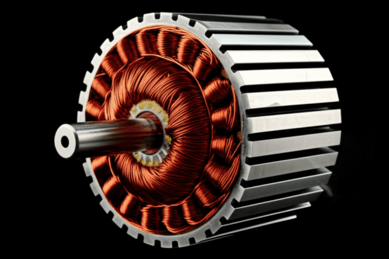
Quick picture. Your engine spins a rotor with magnets. That moving magnetic field cuts across copper windings in the stator. The stator sits still inside the engine case which is why we call it the stator. It generates Alternating Current (AC). The rectifier/regulator turns that AC into Direct Current (DC) and controls voltage to charge the battery and run lights. This whole thing is the charging system. Some people call it an alternator. On bikes and small engines that alternator is a permanent magnet rotor plus a fixed stator.
Why do stators fail? Heat cooks insulation. Vibration loosens connections. Wire chafing rubs through enamel. Oil contamination and poor oil flow can trap heat. A weak or failing rectifier/regulator can overload the stator and push it over the edge. I have seen darkened windings brittle connectors and a burnt smell that hits you the moment you crack the cover. That smell does not lie.
Material and build quality matter. The way the stator core lamination stack is stamped and insulated influences heat and efficiency. The quality of the electrical steel laminations affects losses and hot spots. Even the rotor’s magnet strength and the fit of the rotor core lamination play a role. More on physical inspection later.
Symptoms That Point Me to the Stator
When I see any of these I put stator testing on the short list:
- Battery not charging or frequent dead battery
- Dimming or flickering headlights or dash lights that brighten with RPM
- Engine stalling at idle or misfiring at low voltage
- A burnt or varnish-like smell from the left side cover or generator cover
- Visible discoloration or charred windings during inspection
- Outboards with no-spark issues that trace back to charge coils on the stator
- Intermittent output that drops out when hot then returns when cool
These symptoms overlap with a bad regulator/rectifier or bad wiring. So I test the stator directly. Then I check the rectifier and the battery.
Tools I Actually Use for Stator Testing
You do not need a lab. Here is what I keep on the bench:
- Digital Multimeter (DMM) that can read AC Volts, DC Volts, Ohms, and continuity
- Alligator clip test leads and sharp probes
- Service manual or spec sheet for your exact engine. OEM specs matter for resistance and AC voltage
- Basic hand tools to access connectors. Sometimes you need to pull a cover
- Safety glasses and gloves
- Optional but handy: oscilloscope for waveforms, clamp meter for AC current, infrared thermometer for heat checks, and a megohmmeter for insulation resistance if you have one
Before You Start: Safety, Wire ID, and Specs
I start with a quick look at the wiring diagram and the stator connector. Most motorcycle and ATV charging stators are three-phase. You will usually see three yellow wires. Some small engines and older machines use a single-phase or two-wire stator coil. Outboards often have separate charge coils for ignition and separate lighting or charging coils. Color codes vary which is why the manual matters.
A few basics I follow every time:
- Work in a ventilated area with the machine on a stable stand or center stand
- For resistance and ground tests disconnect the battery negative first
- For AC voltage tests reconnect the battery and keep body parts clear of the chain, belt, prop, or fan
- Clean the connector pins so you get solid contact with your probes
- Zero your meter leads for very low Ohms readings. Use the relative or zero function if your meter has it
Step-by-Step Stator Testing
I break stator testing into three core tests. AC voltage output with the engine running. Winding resistance with the engine off. Ground continuity with the engine off. Those three tell you almost everything.
Preparation and safety first
- Locate the stator connector and disconnect it from the rectifier/regulator
- Identify the stator output wires. Most three-phase stators have three yellows and no polarity. A two-wire stator will have two wires that you test against each other
- Have the spec handy for AC voltage at idle and at test RPM, plus winding resistance
Safety reminder. Keep loose clothing away from spinning parts. Keep the battery connected only for voltage tests. For resistance and continuity remove the negative battery cable.
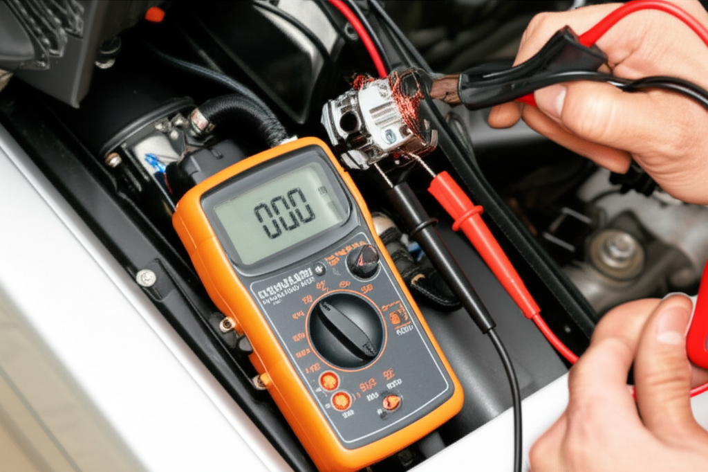
Test 1: Stator AC voltage output test (engine running)
Purpose: Measure the raw AC output the stator produces before the rectifier/regulator touches it.
Steps I use:
- Three-phase stator: test A-B, B-C, and A-C
- Two-wire stator: test the only pair you have
What I expect to see:
- Idle AC voltage often lands in the 20 to 70 VAC range depending on system size
- At 3000 to 5000 RPM I often see 50 to 100+ VAC on many motorcycles and ATVs. Some larger or high output systems can reach 150 VAC. Always check OEM spec
- All three phases should match closely. A spread like 60 V, 58 V, 59 V looks fine. A spread like 60 V, 60 V, 20 V points to a failed phase
Notes:
- This is an open circuit test. We are measuring without the rectifier/regulator loading the stator. If values look weak yet not dead I sometimes repeat with a modest load connected through the R/R to see how the system behaves under load
- If you get zero on all pairs check the rotor magnets and the connector. The rotor might have sheared a key or the connector pins might be loose or corroded
Test 2: Stator winding resistance test (engine off)
Purpose: Find open circuits or internal shorts in the windings.
Steps I use:
- Three-phase stator: measure A-B, B-C, and A-C
- Two-wire stator: measure the single pair
What the readings mean:
- Good stator: Very low and consistent between all pairs. Values match or land close to the spec
- Open circuit: Meter shows OL or infinite resistance between a pair. That phase is broken
- Shorted winding: Meter reads near zero or much lower than spec across a pair. That usually points to internal shorts or melted enamel
- Temperature affects copper resistance. A very hot stator will read higher than a cold one. A small change is fine. A big jump is suspicious
Pro tip. Subtract your lead resistance if your meter does not have a relative mode. Touch the probes together note the reading then subtract that from your measurement.
Test 3: Stator ground continuity test (engine off)
Purpose: Confirm no winding is shorted to the engine case.
Steps I use:
What I expect:
- Good stator: No continuity and infinite resistance. Your meter shows OL and does not beep
- Bad stator: Any measurable resistance or a beep means the windings have shorted to ground. That stator needs repair or replacement
Optional advanced checks: scope patterns and insulation tests
Sometimes the basic tests pass yet the system still acts up. When that happens I dig deeper.
- Oscilloscope stator test: I connect a scope to each phase while the engine runs. A healthy permanent magnet stator produces clean sine-like waveforms with equal amplitude and spacing. Rising RPM increases amplitude and frequency. A collapsed phase drops amplitude. A flat line marks a dead phase. Severe ripple or noise points to a mechanical issue like a loose rotor or damaged magnets
- Insulation resistance (megger): With the stator disconnected I test winding to ground at 250 to 500 V on a megohmmeter. I want very high resistance to ground. Many good stators show tens to hundreds of megaohms. Anything in the low megaohm or kilohm range screams insulation breakdown. Do not megger through the rectifier/regulator. Disconnect the stator fully so you do not damage electronics
- Interturn short check: A DMM often cannot see interturn shorts because total resistance barely changes. A scope imbalance under load or specialized testers catch this. If your AC voltage test shows one phase a little low at RPM and your scope shows distortion you may have an interturn short brewing
How I Interpret Results and What I Do Next
- All tests pass and AC output looks healthy. I move to the rectifier/regulator test and the battery. I check charging voltage at the battery with the system connected. At idle I expect roughly 13.2 to 14.8 V DC depending on the bike. At 3k to 5k RPM I still expect a controlled 13.5 to 14.8 V DC. If voltage stays low yet the stator AC is strong I suspect the R/R or a wiring harness issue. I also check voltage drop between the R/R DC output and the battery positive under load
- Failed AC voltage test. Stator coils are not generating enough power. I look for a weak phase imbalance or zero output on a phase. If the connector and wiring look good I plan a stator replacement. I also inspect the rotor magnets and keyway. A slipped or demagnetized rotor can sink output
- Failed resistance test. Open or shorted winding. Replacement time
- Failed ground continuity test. The winding insulation failed and shorted to ground. Replacement time
- Intermittent results. Heat related failures show up after a few minutes. I warm the engine and repeat the AC test. I have found stators that pass cold and drop a phase when hot. That usually means insulation damage that opens when copper expands
If the stator is good I test the rectifier/regulator:
- Diode test: With the R/R disconnected I use the DMM diode mode between the input AC pins and the DC output pins. I look for standard forward voltage in one direction and OL in the other. Each manufacturer uses a slightly different bridge layout. Follow a diagram if needed
- Bypass test: If I suspect the R/R I sometimes connect a known good unit temporarily. I verify charging voltage at the battery again. If voltage snaps into spec the old R/R was the culprit
Do not forget the battery:
- Fully charge then load test or at least watch its voltage hold under starter draw. A weak battery can mimic a charging fault
- Check grounds and the main harness connectors. Corroded grounds ruin good days
Application Notes: Motorcycles, ATVs, Outboards, and Small Engines
The principles do not change but the wiring does. Here is how I approach each.
Motorcycle stator testing:
- Most modern bikes use a three-phase permanent magnet stator with three yellow wires. Follow the three-pair AC and Ohms tests
- Typical idle AC can be 20 to 70 VAC per pair. Typical 3k to 5k RPM can be 60 to 100+ VAC per pair
- Regulators vary. Some are shunt regulators. Some are series. A failing shunt regulator can run the stator hotter than it should
ATV stator test:
- ATVs often mirror motorcycles. Watch for extra leads for lighting or ignition pickup sensors near the same harness
- Mud and water intrusion corrode connectors fast. Pull back boots and inspect pins closely
Outboard stator test:
- Outboards may combine charging coils for the battery and separate coils for the ignition system. If you have no spark the ignition charge coil on the stator may be bad. Your service manual will show separate resistance ranges for charge and lighting coils
- AC output tests are the same. Measure between coil leads as spec’d. Compare to the manual at a specific RPM on the hose or in a tank. Respect ventilation and prop safety
Small engine stator test:
- Lawnmowers and generators often use a two-wire single-phase stator for charging and lights. Test the single pair for AC voltage at governed RPM. Test the pair’s resistance and check to ground for shorts
- Some small engines output DC directly through a simple rectifier. In that case test AC on the stator side of the rectifier then test DC on the battery side
Three-phase vs single-phase:
- Three-phase: balanced AC across three wire pairs. If one pair is much lower than the others you found the bad phase
- Single-phase: one pair only. Values should meet spec or the coil is weak or open
Two-wire vs six-wire stators:
- Two-wire is usually a single coil or single-phase output. Test the pair and test to ground
- Six-wire can be dual outputs or dual stator sections. Follow the service manual to identify pairs. Test each pair separately
Visual Inspection Tips and Common Failure Causes
I trust my eyes almost as much as my meter. When I pull a cover I look for:
- Burnt or darkened windings
- Cracked or swollen epoxy
- Melted or brittle insulation
- Wire chafing where the harness exits the case
- Metal dust or debris around the rotor
- Oil that smells burnt or looks sludgy near the windings
- Loose hardware or elongated bolt holes that hint at vibration
Stator windings sit on a laminated iron core. Poor lamination stack quality increases eddy current losses and heat. That heat kills insulation. If you geek out on hardware like I do you will appreciate how well made motor core laminations reduce heat and noise. The same goes for the rotor and the magnet circuit. A slipped magnet or damaged rotor core lamination can change the air gap and hurt output.
Primary failure causes I see:
- Heat degradation from long idling in hot weather or heavy loads
- Vibration from loose mounts that rub through enamel
- Oil starvation or the wrong oil that traps heat and bakes the windings
- Manufacturing defects that take time to show
- A bad regulator/rectifier that overstresses the stator
- Wire chafing at grommets which creates ground faults
Common Mistakes I See and How to Avoid Them
- Measuring DC instead of AC on the stator connector. Select AC volts for the stator side
- Testing resistance with the battery connected. Pull the negative cable first
- Trusting low Ohms readings without zeroing the meter. Lead resistance can hide a real short
- Comparing your buddy’s voltage numbers instead of the spec. Output varies by design
- Skipping the ground continuity test. Many stators fail by shorting to ground
- Replacing the stator without fixing the root cause. A failing R/R can kill your new stator fast
- Probing through dirty connectors. Clean the pins so you do not chase ghosts
- Ignoring wiring harness voltage drop. The stator can be fine and the harness can steal your charge
Repair vs Replacement: My Rule of Thumb
If a stator fails any core test I replace it or send it for a professional rewind. DIY rewinds exist. I do not recommend them unless you know insulation systems and have the right varnish and bake process. OEM stators usually last longest. Quality aftermarket units can work well too. Cheap windings with poor varnish can run hot and fail early.
I replace or at least test the rectifier/regulator any time I replace a stator. I repair bad grounds and replace burnt connectors. If the harness is suspect I replace that section. If you run accessories like heated gear or extra lights make sure the system can handle the load. Overloading raises temps and shortens life.
Rewind vs replace:
- Rewinding can save money on rare models. It depends on labor cost and turnaround time
- Replacement is faster if parts are available. I choose the path that gets you back riding without repeat failures
Frequently Asked Questions
Q: Can I test a stator without the engine running?
A: You can test resistance and ground with the engine off. Those tests catch opens and shorts. You cannot confirm output without the engine running since AC voltage depends on RPM.
Q: What are typical normal stator voltage readings?
A: It varies by machine. As a rough guide I often see 20 to 70 VAC per pair at idle and 60 to 100+ VAC per pair at 3k to 5k RPM on many motorcycles. Some systems exceed 150 VAC at higher RPM. Always check the OEM spec.
Q: How do I check a stator with a multimeter?
A: Three tests. AC voltage output at idle and at the spec RPM. Winding resistance between stator wires with the engine off. Continuity to ground between each wire and the engine case with the engine off.
Q: How do I identify stator wires?
A: The charging stator typically has three same-color wires on three-phase systems. Many brands use yellow. Two-wire systems have two same-color wires. Consult the service manual for color codes.
Q: How do I test a 3 phase stator vs a single phase stator?
A: Three-phase: measure AC across all three pairs A-B, B-C, A-C. Compare values and check for balance. Single-phase or two-wire: measure the one pair. Then test each wire to ground.
Q: Can I test a stator without a regulator?
A: Yes. In fact you must disconnect the stator from the rectifier/regulator for the raw AC voltage test and all Ohms tests. That isolates the stator for accurate readings.
Q: Can a bad regulator/rectifier mimic stator symptoms?
A: Absolutely. A bad R/R can undercharge or overcharge. If your stator AC output is strong and consistent but battery voltage stays low or spikes high suspect the R/R.
Q: What about a rectifier/regulator bypass test?
A: You can temporarily connect a known good R/R to see if charging voltage returns to normal. That is a quick way to confirm a failing R/R when the stator tests good.
Q: How long do stators usually last?
A: Many run for years and tens of thousands of miles. Heat and usage patterns matter. Idling in hot weather with high electrical loads shortens life.
Q: What are signs of a bad stator beyond tests?
A: Burnt smell. Discolored windings. Brittle insulation. Oil darkening near the generator cover. Intermittent charging that fails hot then works cold.
Q: Can a stator cause no-spark issues?
A: On some systems the ignition charge coil is part of the stator assembly. If that coil fails you get weak or no spark. Follow the ignition coil resistance specs in your manual.
Q: What is a good resistance between stator wires?
A: Many fall between 0.1 and 0.5 Ohms but your spec wins. Consistency across phases matters.
Q: What is a stator ground test and how do I do it?
A: It checks for a short to the engine case. With the stator disconnected put one probe on a stator wire and the other on a clean engine ground. The meter should show OL. Any reading means trouble.
Q: Should I use an oscilloscope for stator testing?
A: Not required. It helps when you suspect interturn shorts or phase imbalance that does not show on a DMM. It also helps catch intermittent issues at specific RPMs.
Q: What is a stator open circuit test vs a load test?
A: The open circuit test measures AC voltage with the stator disconnected from the R/R. A load test measures system performance with the R/R connected and the bike powering lights and charging the battery. I use both when I chase tricky faults.
Q: What about insulation resistance or a megger test?
A: With the stator disconnected a megger test to ground should show very high resistance. Low readings indicate insulation breakdown. Do not megger through electronics.
Q: Do alternator and stator mean the same thing?
A: On bikes and small engines the alternator often refers to the stator and rotor together. The stator is the stationary winding. The rotor spins with magnets. The rectifier/regulator makes DC for the battery.
Q: Can I repair burned stator wires?
A: You can patch connectors and short harness sections. If the windings burned or the insulation failed you need a rewind or replacement.
Conclusion: Keep Your Charging System Healthy
You do not need guesswork to diagnose a charging problem. A stator test takes minutes and gives clear answers. Measure AC voltage at idle and at RPM. Measure resistance between stator wires. Check for continuity to ground. Compare to the manual. If the stator passes shift focus to the rectifier/regulator and the battery. If it fails replace or rewind then fix the root cause so it does not fail again.
I learned this the hard way by chasing symptoms. Now I start with the stator because it is the heart of the AC side and it is easy to test with a multimeter. Understand the basics and you will solve most no-charge conditions without breaking the bank.
Finally a quick thought on build quality. The copper gets the headlines. The iron stack does the quiet work. Well engineered stator core lamination stacks and high grade electrical steel laminations reduce heat that wrecks insulation. Pair that with a healthy rotor and a solid rectifier/regulator and your charging system stays happy for years.