How to Test an Outboard Motor Stator: A Step-by-Step DIY Guide
Short summary: In this simple guide, I show you how to test your outboard motor stator. You will learn clear steps for resistance, AC voltage, and ground tests. I use easy tools like a digital multimeter and a DVA adapter. Follow along to spot no-spark issues and charging problems. Save time. Save money. Get back on the water with confidence.
Why this is worth reading: You get straight answers. You get real numbers. You get the exact tests that marine mechanics use. You also see how to avoid common mistakes that cost you cash.
Table of Contents
- Why does your outboard stator need testing?
- What are the symptoms of a failing outboard stator?
- What tools do you need for stator testing?
- How do you stay safe before you begin?
- What is the stator and how does it work?
- How do you do a visual inspection first?
- How do you run a resistance test with an ohmmeter?
- How do you check AC voltage output with a DVA adapter?
- How do you test for shorts to ground?
- How do you read your results and decide good vs bad?
- What if the stator tests good but you still have issues?
- When should you replace the stator and what should you buy?
- Do different brands need different test steps?
- Two short case stories from the water
- FAQs (quick hits)
- Key takeaways
Why does your outboard stator need testing?
Problem: Your boat will not start. The battery keeps dying. The engine runs rough. You feel stuck at the dock while the sun and wind call your name. I have been there. It stinks.
Agitate: You replace parts at random. You burn hours. You spend money. Still no spark or no charge. You feel lost because electricity can seem tricky.
Solution: Test the stator. The stator drives two big systems. The charging system and the ignition system. If the stator fails you get no spark or no charging or both. A quick stator test tells you if the stator is fine or if you should look at the rectifier/regulator, CDI, ignition coil, wiring harness, or flywheel magnets next. When you run these tests you stop guessing and you start fixing.
What are the symptoms of a failing outboard stator?
You can spot stator trouble if you look at two groups of signs.
- Charging system issues:
- Battery not charging
- Battery drain
- Low DC voltage at the battery
- Dim lights or electronics
- Engine runs only on the battery then dies
- Ignition system issues:
- No spark or weak spark
- Engine will not start or hard to start
- Misfires and rough idle
- Power loss outboard stator symptoms
- Engine cutting out at high RPM or at low RPM
- Intermittent spark that comes and goes
These same clues show up across brands like Yamaha Outboards, Mercury Marine, Johnson Outboards, Evinrude Outboards, Suzuki Marine, Honda Marine, and Tohatsu. The stator plays a key role in both the charging system and the ignition system. That is why you check it early.
What tools do you need for stator testing?
You do not need a shop full of tools. Grab these and you are set.
- Digital Multimeter (DMM) with Ohm and AC Voltage functions
- DVA adapter or Peak Voltage Adapter for accurate peak AC voltage
- Outboard Service Manual with stator resistance and voltage specs
- Basic hand tools like wrenches and screwdrivers
- Safety Glasses and Gloves as PPE
- Kill Switch lanyard to make sure the engine will not start
If you do not have a DVA you can still test some parts of the stator. Yet most service manuals list peak voltage values. A DVA helps you see those values clearly. It clips between your test leads and your meter. It stores the peak voltage so you can read it while the engine cranks.
How do you stay safe before you begin?
I like my fingers. You like yours too. Let’s keep them.
- Disconnect battery terminals before resistance tests
- Make sure the engine is off and cool
- Remove spark plug caps or ground the plugs so the engine will not fire
- Work in a well-ventilated area with no fuel vapors
- Wear Safety Glasses
- Use good Test Leads with clean tips
- Keep the Kill Switch engaged when you crank for voltage tests
Do not skip safety. Boats and electricity do not forgive mistakes.
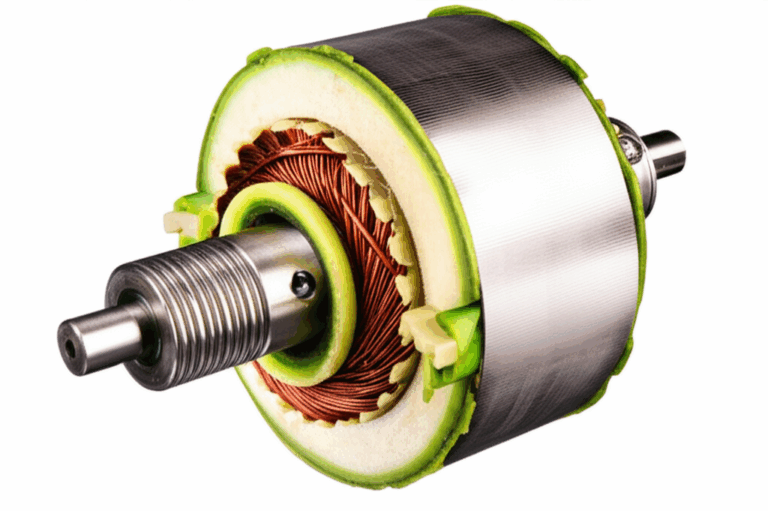
What is the stator and how does it work?
The stator sits under the Flywheel. The flywheel has Magnets. As the flywheel spins those magnets pass over Coil Windings on the stator. This action makes Alternating Current or AC Voltage. The stator has two main sets of coils.
- Charging coils feed AC Voltage to the Rectifier/Regulator. That part turns AC into DC Voltage to charge the Battery.
- Ignition coils like the Exciter Coil and Pulser Coil or Trigger Coil feed AC Voltage to the CDI or ECM. The CDI charges and fires the Ignition Coil. The Ignition Coil makes spark at the Spark Plug.
This same magneto stator idea sits at the heart of your Marine Engine. It is simple and tough. Yet salt, heat, and vibration can hurt it. Overheating stator issues and insulation breakdown can happen. Corrosion can eat wire and connectors.
Note: Good stators start with good core steel. Better lamination stacks reduce losses and heat. In our work we see fewer failures when the stator uses quality stator core lamination and tight winding care.
How do you do a visual inspection first?
Start with your eyes. I always do. You may not need a meter to spot a bad stator.
- Remove the flywheel if your manual says to and if needed
- Look for burnt, melted, or discolored windings
- Check for cracked or frayed wires
- Look for exposed copper and broken Insulation
- Check connectors for Corrosion and Heat Damage
- Inspect Flywheel Magnets for chips or loose parts
If you see melted spots or broken wires you found the problem. If it looks clean move on to the Ohms test.
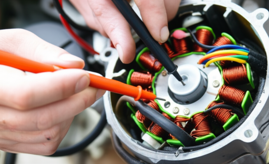
How do you run a resistance test with an ohmmeter?
A resistance test checks Coil Windings for open circuits and shorts. It is fast and simple.
Steps:
What you should see:
- Charging coils often read 0.1 to 1.5 Ohms between leads
- Exciter coils often read 50 to 2000 Ohms
- Pulser or Trigger coils often read 20 to 500 Ohms
- OL on your meter means Open Circuit
- A near zero reading to ground means Short Circuit or ground fault
Compare your readings to the Service Manual stator specifications for your model. If the numbers are way off you likely have a bad stator.
How do you check AC voltage output with a DVA adapter?
Resistance checks the health of the windings. Voltage checks the power the stator makes under load. You need this test when you chase no spark or weak spark and when you chase no charge.
Steps:
What you should see at cranking speed:
- Charging stator AC peak voltage: about 20 to 80V AC peak via DVA. It can go higher with RPM
- Ignition Exciter coil AC peak voltage: about 100 to 250V AC peak via DVA. It often climbs with RPM
- Pulser/Trigger coil voltage is smaller yet the manual lists the exact spec
Low or zero values point to weak or dead coils. Good values tell you to test the Rectifier/Regulator, CDI, or Ignition Coil next.
How do you test for shorts to ground?
A ground fault drops your output to nothing. You can find it fast.
Steps:
You should see OL or infinite resistance. Any low resistance to ground means a short. That is a failed stator.
How do you read your results and decide good vs bad?
I like to think in four tests. Visual. Resistance. AC Voltage. Ground.
- Good stator:
- No burns or broken wires
- Resistance within the Service Manual range
- AC Voltage output meets or beats spec at cranking RPM
- No continuity to ground on isolated wires
- Bad stator:
- Visible burns or melted spots
- Resistance readings show OL where there should be a value
- Resistance readings show near zero where there should be more
- AC Voltage output low or zero
- Short to ground
Use the PAS flow in your mind. Problem: no spark or no charge. Agitate: you miss fishing and lose time. Solution: test and confirm with numbers then fix the exact cause.
What if the stator tests good but you still have issues?
Do not stop. Do the next checks in the right order.
- Rectifier/Regulator test: If charging AC from the stator is good but the Battery DC is low your Rectifier/Regulator can be bad. Follow the manual for diode tests and DC output checks
- CDI unit test outboard: If the Exciter coil voltage is good but you still have no spark the CDI may fail. Some manuals give peak input and output specs for the CDI
- Ignition Coil test outboard: Primary and secondary resistance checks. A spark gap tester also helps
- Flywheel magnets check: Weak or missing magnets can cut output
- Wiring harness inspection outboard: Look for bad connectors and broken wires
- Outboard motor electrical diagram: Study it. Trace power from the stator to the load
If the stator tests good you can rule it out and focus on the next suspect. That saves money.
When should you replace the stator and what should you buy?
Replace the stator when:
- You see visual damage
- Resistance is out of range or shows Open Circuit
- There is a Short Circuit to ground
- DVA peak voltage is well below spec
Stator replacement cost depends on brand and model. The job can be simple or complex. Many DIY boaters can do it with basic tools. If you feel unsure take it to a Mechanic or Marine electrical repair shop.
I also check part quality. The core steel and stack design matter. Good motor core laminations and tight winding work run cooler at high RPM. Good electrical steel laminations resist losses and heat. Do not forget the rotor. The magnet rotor depends on precise rotor core lamination. Better parts mean fewer failures from insulation breakdown and overheating.
OEM vs aftermarket:
- OEM works well yet can cost more
- Aftermarket can save money yet you must pick a trusted brand
- Read reviews and check specs before you buy
Do different brands need different test steps?
The big steps stay the same across Yamaha, Mercury, Johnson, Evinrude, Suzuki, Honda, and Tohatsu. Yet wire colors, specs, and connectors vary. Always use your Service Manual for the exact stator resistance and peak voltage specs.
- Yamaha outboard stator test: Watch exciter coil values for CDI based systems. Pulser inputs can be critical for timing
- Mercury outboard stator test: Some have dual charging windings and split ignition outputs. Your model may list separate ranges by serial number
- Johnson and Evinrude outboard stator test: OMC systems use specific DVA peak windows. Follow the chart for 2 stroke models
- Suzuki and Honda outboard stator test: Many 4 stroke models list higher charging output at idle. Check the manual for both cranking and idle specs
- Tohatsu outboard stator test: Simple and robust. Wire colors help. Values fall in the typical ranges posted below
Keep an eye on 2 stroke outboard stator test vs 4 stroke outboard stator test. Firing needs and charging loads differ a bit. Yet the core idea stays the same.
How do the numbers look? Typical specs you can expect
The Service Manual is king. Still these ranges help you get a feel for what is normal.
Table: Typical Stator Test Numbers and What They Mean
| Test Item | Typical Value Range | What It Tells You |
|---|---|---|
| Charging Coil Resistance (Ohms) | 0.1 to 1.5 Ω between leads | Very low reading to ground points to a short. OL between leads points to an open circuit |
| Exciter Coil Resistance (Ohms) | 50 to 2000 Ω between leads | Out of spec can mean internal short or open circuit |
| Pulser/Trigger Coil Resistance (Ohms) | 20 to 500 Ω between leads | Bad values cause misfire or no spark |
| Charging AC Peak Voltage (DVA) | 20 to 80V AC at cranking RPM | Low means weak charging stator or flywheel magnet issue |
| Exciter AC Peak Voltage (DVA) | 100 to 250V AC at cranking RPM | Low means no or weak spark at the plugs |
| Ground Test | OL or infinite to ground | Any low ohm value to ground means a fault |
Note: Values rise with RPM. If they do not rise at all you may have a stator or flywheel magnet problem.
Two short case stories from the water
Case 1: A Mercury 115 hp 2 stroke starts to misfire then dies. I check spark and find weak spark on two cylinders. DVA on the Exciter coil shows 70V AC peak. The spec calls for 180V or more at cranking. I pull the flywheel and see melted Insulation on one side of the stator. I replace the stator and the engine fires strong.
Case 2: A Yamaha F150 will not charge the battery. The Rectifier/Regulator checks fine. I run a resistance test on the charging coils. One pair reads 0.05 Ohms where the spec says 0.2 to 0.4 Ohms. Another pair shows OL. That tells me one coil is shorted and one coil is open. New stator fixes the charge problem.
What causes stators to fail and how can you avoid it?
- Heat Damage from poor ventilation or locked cooling passages
- Insulation breakdown from age and vibration
- Corrosion from salt and moisture in connectors and Coil Windings
- Short Circuit from pinched wires
- Open Circuit from broken wires
- Overheating stator issues from bad Rectifier/Regulator that forces excess current
Prevention tips:
- Keep connectors clean and dry
- Use dielectric grease on plugs
- Check the Wiring Harness for rub points
- Make sure the Rectifier/Regulator tests good
- Check the battery for proper size and health so the charging system stays in range
- Make sure magnets on the flywheel are tight and clean
Better build quality matters too. High grade stator core lamination and precise winding can run cooler. Good materials in the core and coils pay off for long life.
Can you test without a DVA adapter?
Yes you can do basic tests without a DVA. You can measure resistance with the Ohmmeter. You can measure simple AC Voltage on the charging circuit with a standard meter. Yet most manuals use peak voltage numbers because the stator feeds pulsed AC. A standard meter misses the peak. A DVA adapter or Peak Voltage Adapter stores the peak so you can read it. If you want accurate numbers for no spark troubleshooting invest in a DVA.
What else can look like a bad stator but is not?
- Bad Rectifier/Regulator that blocks DC charging
- Bad CDI unit that cannot hold a charge
- Bad Ignition Coil with a shorted secondary
- Broken Kill Switch or lanyard circuit that grounds spark
- Loose Flywheel key that throws timing off
- Weak or missing Flywheel Magnets
- Bad Grounds on the block and battery
- Faulty Battery that drags the system down
This is why I test in a sequence. You start with visual and resistance. Then voltage with DVA. Then you check the next parts in line. This sequence keeps you from swapping good parts for no reason.
PAS in action: your quick plan to fix the pain
- Problem: No spark. Battery not charging. Engine dies at high RPM. You search how to check outboard stator and you want clear steps
- Agitate: You miss the fish. The kids get sad. Your weekend slips away. You spend money on parts that do not fix it
- Solution: Follow this guide. Run the stator resistance test outboard. Run the DVA adapter stator test. Check the rectifier regulator test. Check CDI unit test outboard and ignition coil test outboard. Use the proper stator test sequence to confirm or rule out the stator. Then replace only what is bad
Useful charts and specs you can print
Table: Symptom to Test Map
| Symptom | First Test | Second Test | Likely Culprit |
|---|---|---|---|
| Battery not charging | Charging AC Peak Voltage at rectifier input | DC Voltage at battery with engine running | Charging coils or Rectifier/Regulator |
| No spark on all cylinders | Exciter coil DVA to CDI | Pulser/Trigger coil resistance | Stator ignition coils or CDI |
| Intermittent spark | Wiring Harness inspection | DVA at various RPM | Loose connectors or failing stator |
| Engine dies at high RPM | DVA rise with RPM | Rectifier/Regulator heat check | Weak stator or failing regulator |
| Rough idle and misfire | Pulser/Trigger coil resistance | Spark plug and Ignition Coil test | Trigger coil or ignition coil |
Brand notes and tips you can use today
- Yamaha: Many models list Exciter coil peak above 150V at cranking. Check Pulser coil ohms for timing faults
- Mercury: Some models split stator outputs for ignition and charge. Follow serial number based specs
- Johnson/Evinrude: OMC charts rely on DVA peak. Use a proper DVA adapter for accurate results
- Suzuki/Honda: 4 stroke outboards often show higher charge output at idle. Use both cranking and idle specs
- Tohatsu: Simple harness and clear colors. Keep an eye on ground faults
Always match your Service Manual stator values. If you do not have the factory manual a Seloc or Clymer guide can help with typical stator resistance charts and AC voltage output charts.
Simple checklist before you buy a new stator
- Visual inspection stator complete
- Stator continuity test done
- Open circuit stator test confirmed
- Ground fault stator test done
- Stator resistance readings compared to the service manual stator values
- Stator AC voltage output test with DVA done at cranking RPM
- Rectifier/Regulator test done
- CDI and Ignition Coil checked
- Flywheel magnets check done
- Wiring harness inspection outboard done
- You decided when to replace stator based on data not hunches
FAQs (quick hits)
Q: What is a stator in an outboard
A: It is a set of coils under the flywheel that makes AC voltage for charging and ignition.
Q: How many ohms should a stator have
A: Charging coils often read 0.1 to 1.5 Ohms. Exciter coils often read 50 to 2000 Ohms. Trigger coils often read 20 to 500 Ohms. Check your Service Manual for exact numbers.
Q: Can I test a stator without a DVA
A: Yes for resistance and basic AC. For ignition peak voltage you should use a DVA.
Q: What causes a stator to fail
A: Heat, corrosion, insulation breakdown, vibration, shorts, and open windings.
Q: When should I call a mechanic
A: If you lack a DVA, if your flywheel will not come off, or if you feel unsafe.
References
- Yamaha, Mercury, Johnson/Evinrude, Suzuki, Honda, and Tohatsu Factory Service Manuals
- CDI Electronics Ignition Troubleshooting Guide and DVA procedures
- Seloc and Clymer marine service manuals for stator specifications and diagrams
- Marine electrical best practices for diagnostics and safety
Final word on quality parts
If you must replace the stator pick parts built on good steel and tight stacks. Strong cores lower losses and heat. That means longer life for your charging and ignition coils. We have seen solid results when builders use precise stator core lamination, engineered electrical steel laminations, and well designed motor core laminations. Better cores make better stators. Better stators keep you off the trailer and on the water.
Key takeaways
- A bad stator can cause no spark, weak spark, or no charge
- Start with a visual check then test resistance, AC peak voltage with a DVA, and ground faults
- Compare all readings to your Service Manual
- Low DVA readings point to a weak or dead stator
- If the stator tests good test the Rectifier/Regulator, CDI, Ignition Coil, Flywheel Magnets, Battery, and Wiring Harness
- Use safety steps every time
- Quality core laminations and winding care improve stator life
- Test smart so you replace only what is bad and save money
- Keep a simple toolkit handy so you can diagnose fast and get back to fun on the water
Table: Quick Spec Recap
| Item | Quick Tip |
|---|---|
| Charging Coil Ohms | 0.1 to 1.5 Ω between leads |
| Exciter Coil Ohms | 50 to 2000 Ω between leads |
| Trigger Coil Ohms | 20 to 500 Ω between leads |
| Charging DVA Peak | 20 to 80V AC at cranking |
| Exciter DVA Peak | 100 to 250V AC at cranking |
| Ground Test | OL to ground is normal |
Stay calm. Follow the steps. You will find the fault and fix it right.