How to Test an Electric Motor with a Multimeter: A Step-by-Step Diagnostic Guide
Every engineer faces the same moment sooner or later. A motor will not start or it hums and trips a breaker. Production waits. You need a fast, reliable way to diagnose the problem. A digital multimeter can do more than give you numbers. It can reveal the story inside the windings, brushes, and connections. If you design motors or buy them for a product line, these tests also tell you something deeper about material choices, manufacturing quality, and even the health of the motor’s laminations. You want clarity and confidence. You want an answer you can act on.
This guide walks you through safe, practical multimeter tests for AC and DC motors. We explain what the readings mean and what to do next. Then we connect the dots to motor laminations and core materials so you can make smarter design and purchasing decisions.
In short, you will troubleshoot with precision and you will understand the “why” behind the symptoms.
In This Article
- Why Test Your Electric Motor? Understanding Common Motor Failures
- Essential Safety First: Preparing for Motor Testing
- Tools You’ll Need
- Before You Test: Pre-Inspection and Preparation
- Step-by-Step Multimeter Tests for Electric Motors
- What Do the Readings Mean? Interpreting Your Multimeter Results
- Common Motor Problems & Next Steps
- Beyond the Multimeter: What Laminations Tell You About Motor Health and Design
- FAQs About Motor Testing
- Conclusion: Empowering Your Motor Diagnostics
Why Test Your Electric Motor? Understanding Common Motor Failures
Motors fail for many reasons. Some issues are electrical like open windings, shorted turns, bad capacitors, or ground faults. Others are mechanical like seized bearings or a blocked fan. Symptoms overlap. The motor hums but won’t start. It trips the circuit breaker. It overheats under normal load. You can guess. Or you can measure and know.
A multimeter gives you a quick, structured path through the noise. You will confirm continuity, measure resistance, and check winding-to-ground isolation. You can test a start or run capacitor. You can validate the brush and commutator path in DC and universal motors. With these data points you can decide fast. Replace a capacitor. Rewind the motor. Investigate a ground fault. Or call in advanced testing if the problem lies deeper in the rotor or supply quality.
This matters for design and procurement too. If failed motors regularly show ground faults and cooked insulation, you might have a thermal management or lamination material problem. If three-phase winding resistances are consistently unbalanced, you might face systematic coil or termination variability. In both cases a better lamination stack or tighter manufacturing process can raise yield and cut field returns.
Essential Safety First: Preparing for Motor Testing
Testing an electric motor safely is non-negotiable. Electricity does not give second chances. Take these steps before you touch a lead.
Disconnect Power: Lockout/Tagout (LOTO)
- Isolate all energy sources. Use proper lockout/tagout on power supplies and control circuits.
- Verify zero voltage at the motor terminals with your meter’s Volts AC/DC setting.
- Discharge capacitors in the control circuit and on the motor. Use a resistor and insulated leads.
Personal Protective Equipment (PPE)
- Wear safety glasses and insulated gloves.
- Use insulated tools in tight junction boxes.
- Keep clear of rotating parts. Mechanical energy still injures when electricity is off.
Visual Inspection
- Look for burn marks, discoloration, cracked insulation, or melted connectors.
- Check for loose terminals, damaged leads, or signs of water ingress.
- Spin the shaft by hand if safe. A seized rotor points to bearings or mechanical load issues.
Tools You’ll Need
- Digital multimeter (DMM) with Ohms, Continuity, Volts, and Capacitance. Analog meters can help for simple charge/discharge checks on capacitors.
- Screwdrivers, wire strippers, and insulated needle probes or alligator clips.
- Pen and paper or a notes app for recording resistance values.
- Optional but useful: clamp meter for current draw, and a megohmmeter for true insulation resistance. The DMM provides a first-pass check. The megohmmeter provides a more sensitive insulation test.
Before You Test: Pre-Inspection and Preparation
- Confirm motor type. AC or DC. Single-phase, three-phase, or universal. Identify capacitor start/run if present.
- Locate the terminal box and wiring diagram. The nameplate and junction box diagram show lead identifiers like T1, T2, T3, or C/S/R for common/start/run.
- Clean terminals. Corrosion or debris can skew readings.
- Disconnect the motor from the drive or controller. Isolate the motor leads from external circuits to avoid backfeeding and false readings.
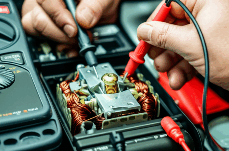
Step-by-Step Multimeter Tests for Electric Motors
These tests work for many motor types. Adjust your approach based on your motor’s wiring diagram and nameplate data.
Test 1: Winding Continuity Check (Open Circuits)
Purpose: Detect broken internal wiring or open windings.
Procedure:
Interpreting Results:
- Good: The meter beeps or shows a low resistance consistent with winding length and gauge.
- Bad: “OL” or infinite resistance indicates an open circuit in a winding or lead.
Test 2: Winding Resistance Test (Shorts and Imbalance)
Purpose: Identify shorted turns and imbalances across windings.
Procedure:
Interpreting Results:
- Good: Three-phase pairs match within roughly 5–10%. Single-phase readings match the pattern expected from the motor diagram.
- Bad: One phase reads significantly lower than the others. That suggests shorted turns. One phase reads “OL.” That indicates an open winding. A reading that is inexplicably high can also signal a high-resistance connection or corroded joint.
Tip: Temperature affects resistance. If possible, compare motors at similar temperatures or use the nameplate data and manufacturer specs.
Test 3: Winding-to-Ground Resistance (Ground Faults)
Purpose: Check for insulation breakdown from windings to ground.
Procedure:
Interpreting Results:
- Good: The meter shows “OL” or a very high resistance in the megaohm range.
- Bad: A measurable low resistance indicates a ground fault. If you read tens of kilohms or lower, you likely have a serious insulation failure.
Note: A digital multimeter has limited test voltage. It can spot severe ground faults. It may not reveal marginal insulation. A megohmmeter applies higher DC voltage and measures insulation resistance more rigorously.
Test 4: Capacitor Test (Start/Run Capacitors in Single-Phase Motors)
Purpose: Validate the start or run capacitor.
Procedure:
Interpreting Results:
- Good: Measured µF within the labeled tolerance.
- Bad: Significantly low, zero, or “OL.” Replace the capacitor.
If your meter lacks a capacitance setting, use a rough analog test. Charge the capacitor with the meter in resistance mode and watch for a rising resistance, then reverse leads to see a similar charging trend. This test is crude and only confirms that the capacitor holds and releases charge.
Test 5: Brush and Commutator Inspection (DC and Universal Motors)
Purpose: Assess wear and contact quality.
Procedure:
Interpreting Results:
- Good: Smooth commutator, adequate brush length, consistent contact.
- Bad: Severely worn or stuck brushes, heavy commutator damage, or erratic continuity.
Optional: Voltage Test at Motor Terminals
If you’re troubleshooting a system that will not start, check supply voltage at the motor terminals with power on and the system secured. Verify you have correct voltage and phase balance. Measure line-to-line and line-to-ground where appropriate. Never perform resistance or continuity tests with power applied.
What Do the Readings Mean? Interpreting Your Multimeter Results
Let’s translate numbers into diagnoses.
- Open winding: Continuity test shows “OL.” Resistance test shows infinite or very high resistance. The motor will not run or it hums without movement.
- Shorted turns: One three-phase pair reads lower than the others. In single-phase motors, one path looks suspiciously low. The motor overheats and trips the breaker under load.
- Ground fault: Winding-to-frame reads a low resistance. Expect breaker trips and potential safety hazards. Remove the motor from service immediately.
- Bad capacitor: The motor hums and fails to start. Capacitance reads low or “OL.” Replacing the capacitor often restores operation.
- Brush/commutator issues: The motor starts inconsistently or runs with arcing and noise. Visual checks show worn brushes or pitting.
Patterns matter. Consistent three-phase imbalance points to winding or connection variability. Ground faults after water exposure suggest environmental sealing challenges. Repeated capacitor failures hint at voltage spikes, heat, or poor component selection. Each pattern can direct a better design choice or supplier conversation.
Common Motor Problems & Next Steps
- Motor dead or no power: Verify power at the supply and motor terminals. Check the circuit breaker and overload protector. Confirm control circuit signals at the Motor Control Center (MCC).
- Motor hums but won’t start: Test the start capacitor and start winding continuity. In capacitor-start motors, a failed capacitor is a prime suspect.
- Motor overheats: Investigate shorted turns, high current draw, and restricted airflow. Check for bearing issues that increase mechanical load.
- Motor trips breaker: Look for short circuits, ground faults, or locked-rotor conditions. Confirm the circuit and overloads match the motor nameplate kW/HP.
- Inconclusive tests: If resistance and continuity look fine yet performance lags, the problem could be rotor bar defects in an induction motor, severe voltage unbalance upstream, or control issues. Consider current signature analysis, thermal imaging, or specialized rotor tests. A clamp meter can help assess current draw against expected values. Follow Ohm’s Law and power relationships for sanity checks under load.
When to call a professional:
- You need an insulation resistance test per a standard procedure at a specified DC test voltage.
- The application is safety critical and downtime costs are high.
- You suspect rotor faults, severe supply quality issues, or drive-related harmonics that require advanced tools.
Beyond the Multimeter: What Laminations Tell You About Motor Health and Design
You can troubleshoot with a meter all day. Yet many root causes trace back to core design choices and lamination quality. If you design or source motors, understanding laminations will help you specify better products and interpret field failures with more precision.
Let’s unpack the essentials without drowning in jargon.
What’s Really Going On? The Engineering Fundamentals
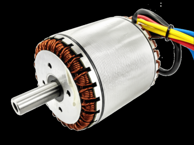
Motor cores are stacks of thin electrical steel sheets called laminations. They guide magnetic flux through the stator and rotor. Two main loss mechanisms dominate in the core:
- Eddy current loss: Changing magnetic fields induce circulating currents in the steel. These “electrical whirlpools” create heat and waste energy.
- Hysteresis loss: The steel consumes energy as it cycles between magnetic states. Think of it like bending a paperclip back and forth until it warms up.
Analogy time. Picture a fast river with whirlpools. Big open water allows large whirlpools that sap energy from the flow. Lamination thickness and insulation act like river walls that break big whirlpools into small, harmless eddies. Thinner laminations with good interlaminar insulation block large eddies and reduce loss. Higher-grade steels reduce hysteresis because their magnetic domains flip with less friction.
The result: less heat, better efficiency, and more headroom before insulation cooks. That protects windings from premature failure and helps your continuity and resistance tests look “normal” for years.
Material Considerations: Selecting the Right Electrical Steel
- Non-oriented silicon steel (CRNGO): Common for general-purpose motors that run in multiple directions. Balanced performance and cost. Good for single-phase and three-phase induction motors in many industrial and HVAC applications.
- Grain-oriented silicon steel (CRGO): Optimized for one direction of flux. Excellent for transformers. Not the first choice for rotating machines that need isotropic properties.
- High-silicon steels and premium grades: Lower core loss at higher frequencies and higher induction levels. Useful for high-efficiency designs and motors driven by variable frequency drives with high switching frequencies.
- Cobalt alloys: High saturation flux density and good high-temperature performance. Ideal for aerospace or very high power density applications. They cost more and need careful handling.
- Amorphous metals: Very low core loss at high frequencies due to non-crystalline structure. Attractive for high-frequency machines and specialized designs. Manufacturing constraints and cost can limit use.
If you want a broad view of base materials and how they translate into components, see this overview of electrical steel laminations.
Key properties to balance:
- Magnetic permeability: How easily the material conducts magnetic flux. Think of it like how easily a sponge absorbs water.
- Core loss vs frequency: Lower is better. Look at manufacturer loss curves at your operating flux density and harmonic content.
- Saturation flux density: Higher allows more torque per volume. Useful when space is tight.
- Coercivity: The material’s resistance to demagnetization. Lower means less hysteresis loss.
- Mechanical and thermal behavior: Strength, punchability for stamping, coating durability, and stability at operating temperature.
Manufacturing & Assembly Processes: Why the Process Matters
It is not just the steel. Process choices reshape performance.
- Stamping: Most cost-effective for medium to high volume. Good dimensional repeatability with proper tool maintenance. Burrs and punch work can raise local core loss if not controlled. Tooling amortizes over volume.
- Laser cutting: Flexible and precise for prototypes and low volume. Heat-affected zones can increase loss unless processes and post-treatments are optimized. Excellent for complex geometries and fast iteration.
- Waterjet and wire EDM: Niche options that avoid heat-affected zones. Slower and often more expensive per part.
- Interlocking vs welding vs bonding:
- Interlocking works like LEGO bricks. Tabs snap laminations together and avoid welding heat. Watch for air gaps and stack factor losses if not controlled.
- Welding adds rigidity yet can locally degrade magnetic properties where heat concentrates.
- Bonding with adhesives or varnish improves interlaminar insulation and mechanical integrity. It can lower audible noise and cut eddy currents further if done well.
Design Details: Stator, Rotor, and Stack Assembly
- Stator lamination quality sets magnetic efficiency and slot consistency for the windings. Better stator design improves power factor, torque ripple, and thermal behavior. Learn how a stator core lamination choice affects slot geometry and winding thermal paths.
- Rotor lamination design and assembly influence cage resistance in induction machines and flux paths in PM and synchronous designs. Rotor bar integrity lies outside what a multimeter can easily test. Rotor losses still translate to heat and stress. Explore how rotor core lamination choices impact performance and lifetime.
- Stack factor matters. More steel per stack height yields higher effective permeability and torque, within limits. Insulation coatings and bonding processes trade stack factor for lower eddy currents and better stability.
You can see integrated options for stators and rotors in typical motor core laminations.
Application Fit: Which Path Matches Your Needs?
- General-purpose industrial motors: CRNGO silicon steel with thicknesses in the 0.35–0.50 mm range often balances cost and performance. Stamping wins for volume. Interlocking or bonding provides robust stacks.
- High-efficiency, VFD-driven motors: Premium non-oriented silicon steels with thinner gauges cut losses at higher frequencies and harmonics. Bonding and careful tooth-tip design help reduce noise and core loss.
- High power density and aerospace: Cobalt alloys or specialty high-saturation steels push performance. Laser cutting can accelerate prototype iterations. Bonding helps maintain rigidity without thermal damage.
- Small appliance and universal motors: Slot geometry and commutation behavior dominate. Lamination thickness and coating control still matter for heat and noise. For BLDC appliances and tools that need tight NVH and high efficiency, consider purpose-built bldc stator core options with precise slot and yoke geometry.
Be honest about constraints. Laser cutting gives you agility for low-volume and complex shapes. Stamping gives you cost and speed for scale. Bonding improves noise and interlaminar insulation. Welding gives ruggedness yet needs careful heat control. Your best fit depends on performance targets, volume, and cost.
Why Laminations Show Up in Field Failures
Your multimeter flags the symptom. Laminations often explain the cause.
- If you see frequent ground faults after moderate service, suspect thermal stress that baked the insulation. That heat could come from higher-than-expected core loss due to material choice or process artifacts like burrs or heat-affected zones.
- If motors run hot under nominal load and pass continuity tests, look at core loss and ventilation pathways. The stator lamination stack might trap heat or the material grade might not match the drive’s switching frequency.
- If an induction motor shows poor torque and current draw seems high, rotor issues or lamination stack consistency might be to blame. Rotor bar defects need specialized tests. Consistent lamination thickness, slot geometry, and stack factor still set the stage for reliable torque production.
Design and purchasing takeaway: pair the multimeter data from returns with a structured review of lamination materials, stack assembly, and process controls. Close the loop with suppliers on loss curves, coating specs, burr height limits, and tooling maintenance plans.
FAQs About Motor Testing
Q: Can I test an electric motor without a multimeter?
A: You can inspect visually and spin the shaft to check bearings. You can sniff for that telltale burnt smell. You cannot confirm open windings, shorts, or ground faults without a meter.
Q: What is a typical resistance for motor windings?
A: It varies widely with motor power, wire gauge, and temperature. Look for balance and pattern. Three-phase pairs should match within roughly 5–10%. Single-phase relationships should match the design topology.
Q: What if my multimeter doesn’t have a capacitance setting?
A: An analog meter can show a charge/discharge trend. A dedicated capacitance meter gives a better answer. In a pinch, swapping in a known-good capacitor can quickly confirm a diagnosis.
Q: Can a multimeter measure a running motor’s health?
A: Use it to check supply voltage while the motor runs. Do not measure resistance or continuity on a live circuit. For deeper running diagnostics, use a clamp meter for current, thermal imaging for hotspots, and vibration analysis for bearings.
Q: Do I need a megohmmeter for insulation tests?
A: A megohmmeter provides a better insulation resistance measurement at specified test voltages. A DMM can only catch gross ground faults. Use the right tool when safety and standards compliance matter.
Q: How often should I test motors?
A: Test during commissioning and troubleshooting. For critical assets, include periodic checks in your preventative or predictive maintenance plan. Capture trends in winding resistance balance and insulation health.
Q: Will these tests cover DC series, shunt, and compound motors?
A: Yes for the basics. Continuity, resistance, and ground checks still apply. Pay special attention to field windings and brush-commutator health. Compare with the wiring diagram to confirm expected paths in series and shunt configurations.
Problem – Explain – Guide – Empower: Your Practical Takeaway
Problem: Motors fail in ways that look similar from the outside. You need to distinguish electrical faults from mechanical issues fast, so you can keep production lines moving and protect your budget. Your design and purchasing choices also influence long-term reliability.
Explain: A digital multimeter helps you diagnose common electrical faults clearly. Continuity and resistance checks flag open windings and shorted turns. Winding-to-ground tests reveal insulation breakdown. Capacitance tests catch dead start and run capacitors. Brush and commutator inspections show DC contact health. Behind the readings lies material physics. Laminations reduce eddy currents and hysteresis, which cuts heat and preserves insulation. That is how core design choices echo through field performance.
Guide: Follow a consistent test flow.
- Lockout/tagout and verify zero energy.
- Inspect visually. Free the shaft and clean contacts.
- Confirm continuity and balanced winding resistance.
- Check winding-to-ground isolation with your DMM. Use a megohmmeter for sensitive insulation tests.
- Verify capacitor values on single-phase motors.
- Inspect brushes and the commutator where applicable.
- If results are inconclusive, step up to specialized diagnostics for rotor and supply issues.
Then zoom out to design and sourcing.
- Match lamination material to frequency content, thermal targets, and efficiency goals.
- Choose manufacturing processes that deliver the geometry you need at your volume.
- Specify coatings, burr limits, and bonding or interlocking strategies that control core losses and noise.
- Align stack factor, slot geometry, and assembly tolerances with winding design.
Empower: You have the data and the why behind it. Use the multimeter to make the immediate call. Repair the lead, swap the capacitor, or schedule a rewind. Use your understanding of laminations to refine the next motor build or the next supplier quote. If you need to dive deeper into stator or rotor options, review focused resources on stator core lamination, rotor core lamination, and end-to-end motor core laminations. For high-frequency or high-efficiency designs, start with the fundamentals of electrical steel laminations. If you build compact drivetrains or appliances, look at bldc stator core choices built for dense windings and quiet operation.
Conclusion: Empowering Your Motor Diagnostics
You do not need guesswork. A structured multimeter workflow gives you answers quickly. You will spot open windings, shorts, ground faults, and bad capacitors. You will separate electrical problems from mechanical ones. You will make decisions that save time and money with confidence.
Step back and you will see a pattern. Many chronic failures trace back to heat and insulation stress. Those forces live in the laminations and their manufacturing. Better materials and processes reduce core losses and stabilize stack geometry. That keeps temperatures in check and extends service life. If you test motors, design them, or buy them, connect both sides of the story. Diagnose today. Design better for tomorrow.
As a next step, capture your resistance and insulation readings in a simple template. Pair those notes with the motor nameplate and lamination specs where available. Use that record to drive a productive conversation with your supplier about materials, stack assembly, and process controls. You will cut failure rates. You will strengthen your product line. You will give your team breathing room when the next motor hums but refuses to turn.
—
Safety reminder: Always follow NEC and local electrical codes. Reference NEMA and manufacturer data for acceptable tolerances and test conditions. When in doubt, consult a qualified electrical professional or a motor repair specialist.