How to Test an Electric Motor: A Comprehensive DIY Guide for Diagnostics, Laminations, and Smart Decisions
Every engineering team faces the same crunch. A motor won’t start or it runs hot or it trips protection upstream. You need a fast, trustworthy motor troubleshooting guide that goes beyond quick fixes. You also want to know what these test results mean for your design choices and purchasing decisions, especially around motor laminations. If that’s you, you’re in the right place.
We’ll walk through AC motor testing procedures and DC motor testing steps you can do with a multimeter, a megohmmeter, and a few other tools. Then we’ll connect your findings to the engineering fundamentals inside the motor core. You’ll see how lamination material and thickness, winding design, and manufacturing choices affect core loss, motor efficiency, and long-term reliability. The goal is simple. Diagnose. Understand. Act. Prevent.
Before we dive in, a quick safety note. Electricity can injure or kill. If you’re not qualified to perform electrical work, stop and bring in a licensed electrician or motor technician. Use proper lockout/tagout procedures and PPE every time.
In This Article
- Introduction: Why Testing Your Electric Motor Matters
- Safety First: Essential Precautions Before Testing
- Essential Tools for Electric Motor Testing
- What’s Really Going On Inside the Core: Losses, Laminations, and Efficiency
- Step-by-Step Motor Testing Procedures
- Interpreting Results and Troubleshooting Common Motor Problems
- Your Options Explained: Lamination Materials and Manufacturing Processes
- Which Application Is This For? Matching Methods to Use Cases
- Data You Can Use: Failure Rates, Cost, and Maintenance Impact
- When to Call a Professional
- Your Engineering Takeaway
Introduction: Why Testing Your Electric Motor Matters
Motor testing sits at the intersection of safety, uptime, and cost. Unplanned downtime can cost five figures per hour in many plants. A failed fan motor can stall a HVAC system and a failed pump can halt production. Electric motor diagnostics keep mission-critical assets healthy and they give you evidence for repair vs replace decisions.
If you design or buy motors or motor-driven systems, testing also verifies that the product you specified works in the field. It validates assumptions about core materials, winding resistance balance, bearing quality, and motor protection devices. Done well, testing closes the loop between design intent and real-world performance. It protects your bill of materials and your schedule.
This guide covers:
- Electrical safety for motor testing
- The essential test instruments and where they shine
- Step-by-step AC and DC motor testing procedures
- Interpreting winding tests, insulation resistance test (IRT) readings, and ground fault tests
- How core losses and motor laminations influence test results and efficiency
- When to escalate to a professional rebuild or rehabilitation
Safety First: Essential Precautions Before Testing
You only test safely when you reduce risk. Follow these best practices before you touch a lead.
- Disconnect power and apply lockout/tagout procedures. Verify the correct MCC bucket or breaker. Hang tags. Use locks. Don’t rely on memory or colored tape.
- Verify zero energy state. Use a voltage tester or a multimeter on the incoming lines and at the motor terminal box. Test your tester on a known live source first. Then confirm de-energized conductors.
- De-energize and discharge capacitors. Single-phase motors often carry start or run capacitors. Discharge with a resistor and insulated leads. Never short a capacitor with a screwdriver.
- Wear appropriate PPE. Use safety glasses and insulated gloves. Arc flash PPE may be required when you must test energized circuits in the motor control center. Consult your arc flash study and NFPA 70E.
- Control the work area. Barricade the space. Remove conductive jewelry. Keep water and conductive dust away from test points.
- Respect nameplate data and limits. Don’t exceed test voltages. Don’t spin shafts with power tools. The nameplate tells you voltage, current, frequency, service factor, insulation class, and temperature rise.
Essential Tools for Electric Motor Testing
A well-equipped tech doesn’t need a lab. You need accurate instruments and a clear plan.
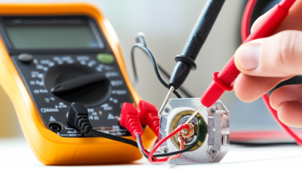
- Multimeter. Your everyday tool for continuity test motor checks, ohm test motor windings, and basic voltage measurements. Select a quality brand like Fluke or AEMC. Accuracy and input protection matter.
- Megohmmeter (Megger). Use it for insulation resistance test (IRT) between windings and ground. Follow IEEE and NEMA guidance for test voltage selection and minimum acceptable readings.
- Clamp meter. Use it to read current draw under load for current balance test motor checks and to capture inrush. Great for voltage drop motor test analysis and phase unbalance motor investigation.
- Growler tester. On DC motors, a growler test armature finds shorted coils in the armature slots quickly. It is simple and effective.
- Optional tools. An infrared camera supports thermal imaging motor surveys. A vibration analyzer with SKF accelerometers helps with diagnosing motor noise and bearing issues. A data logger can trend temperature and current for predictive maintenance motor programs. Motor current signature analysis (MCSA) tools help with rotor bar issues and eccentricity.
What’s Really Going On Inside the Core: Losses, Laminations, and Efficiency
Let’s pop the hood. Why do laminations exist and why do your tests sometimes point back to the core?
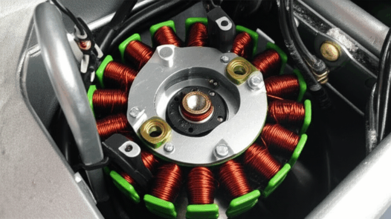
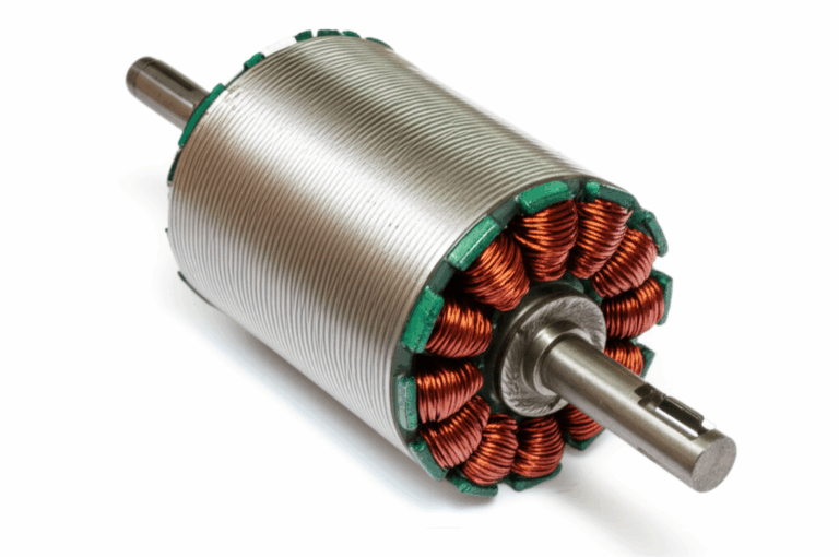
In any AC motor, the stator and rotor see a changing magnetic field. That field flips and swirls like eddies in a river. Those “eddies” drive circulating currents inside solid steel. Engineers call them eddy currents and they waste energy as heat. Laminations exist to break up those electrical whirlpools. Think of thin, insulated slices of steel stacked like pages in a book. Each page blocks the whirlpool from growing large. Smaller whirlpools mean less heat and higher efficiency.
Two main components of core loss matter:
- Eddy current loss. Proportional to the square of frequency and thickness. It falls as you use thinner laminations and better insulation coatings.
- Hysteresis loss. The energy the material spends as the magnetic field traces a loop on the B-H curve. Materials with lower coercivity lose less energy each cycle.
Material choice influences both. Silicon steels (like M-grades) improve magnetic permeability and reduce hysteresis loss. Cobalt alloys can carry higher flux density which supports high power density designs yet they cost more. At higher frequencies, thinner gauges and even amorphous metals can cut loss sharply.
Why does this matter in a motor troubleshooting guide? Because your tests see symptoms. Overheating motor causes can include overloaded windings, blocked ventilation, or high core loss. Insulation resistance falls faster when the core runs hot and moisture condenses during cool-down. Vibration grows when bearings overheat. Your electrical motor health check often circles back to the quiet details inside the lamination stack.
If you want to refresh the basics on lamination families, see how the selection and stacking of electrical steel laminations shapes losses, efficiency, and size.
Step-by-Step Motor Testing Procedures
Use this section as your step-by-step motor check. It applies to most induction motor test methods and synchronous motor testing at a basic level. We’ll flag DC-specific steps where needed.
Visual Inspection (Initial Check)
Start simple. Many motor problems show up in plain sight.
- Inspect the motor terminal box and leads. Look for frayed wires, burnt insulation, loose lugs, and heat discoloration.
- Check vents and cooling fan guards for debris and oil. A clogged fan will cook the windings.
- Look for oil leaks from nearby gearboxes or pumps. Oil attracts dust. Dust insulates heat. Bad combo.
- Inspect the casing for cracks and the shaft for straightness. Verify the key is secure. Check the fan for missing blades.
- Spin the shaft by hand. It should rotate smoothly without gritty feedback or binding. Note any axial or radial play.
This visual inspection informs the rest of your plan. For example, a burnt smell and soot near the terminal box hints at loose connections or a short circuit in motor windings.
Winding Continuity Test (Multimeter)
Purpose: Find open circuits in windings or connections.
Procedure:
- Isolate the motor from the control circuit. Label leads. Separate jumpers in the terminal box if present.
- On a three-phase motor, identify T1, T2, and T3. On a single-phase motor, identify start and run windings.
- Set your multimeter to low ohms. Measure between expected pairs. For three-phase, measure T1-T2, T2-T3, T3-T1.
- For DC motors, check field and armature circuits per the wiring diagram.
Interpretation:
- Near-zero or low ohms means continuity. Infinite ohms means an open circuit. No continuity equals no torque.
- If you see continuity from a winding to the motor frame in ohms mode, stop and do a ground fault test properly.
Winding Resistance Test (Multimeter)
Purpose: Confirm balanced windings on three-phase motors or proper resistance on single-phase motors.
Procedure:
- Use a multimeter or a micro-ohmmeter for better resolution on low-resistance windings. Compensate for lead resistance if possible.
- For three-phase motors, record T1-T2, T2-T3, T3-T1. For single-phase motors, measure start and run windings separately.
Interpretation:
- Three-phase windings should match within 5–10%. Larger differences point to shorted turns, poor connections in the terminal box, or a stator winding issue.
- Compare against motor nameplate data or manufacturer specs when available. Some designs use special winding patterns. Know the context.
Insulation Resistance Test (Megohmmeter/Megger Test)
Purpose: Check for insulation degradation between windings and ground or between windings.
Procedure:
- Select the correct test voltage per IEEE and NEMA guidance. As a rule of thumb, 500 V DC suits motors up to 1000 V. Larger machines may require 1000 V DC or more. Follow the standard and nameplate.
- Test from each winding to the motor frame. On three-phase motors, also test phase-to-phase if the leads are isolated.
- Time the test for 60 seconds to read a stabilized value. For large motors, consider a polarization index test over 10 minutes to compare 10-minute/1-minute values.
Interpretation:
- New, dry windings often read tens to hundreds of megaohms. Readings below 1 MΩ raise a red flag. Moisture, contamination, or insulation damage may be present.
- Follow IEEE/NEMA criteria and your site’s maintenance standards. Track values over time as part of predictive maintenance motor programs.
Ground Fault Test (Multimeter/Megger)
Purpose: Detect direct short from windings to ground.
Procedure:
- With the motor isolated, measure resistance from each winding terminal to the motor frame. Use a megohmmeter for reliable results.
Interpretation:
- Any continuity or low resistance indicates a ground fault. Plan for repair, rewinding, or replacement.
Voltage Balance Test and Current Balance Test (Under Load)
Purpose: Identify supply issues and phase unbalance motor conditions.
Procedure:
- With the motor running, measure line-line voltages at the motor or MCC. Then measure phase currents with a clamp meter.
- Record and compute percent imbalance. IEEE defines acceptable limits. Lower is better.
Interpretation:
- Even small voltage imbalances drive large current imbalances which increase heating. Investigate upstream issues like loose lugs, corroded contacts, or utility supply problems.
Bearing Inspection (Manual, Auditory, and Vibration)
Purpose: Evaluate bearing health which statistically causes most motor failures.
Procedure:
- Rotate the shaft by hand. Feel for roughness or notchiness.
- Use a stethoscope or even a screwdriver pressed to the housing to listen for rumble.
- Apply vibration analysis when available. Look for classic bearing frequencies.
Interpretation:
- Grinding noise, excessive play, or heat near the bearing housings indicates bearing wear. Plan replacement.
Capacitor Test (Single-Phase Motors)
Purpose: Verify start/run capacitor health.
Procedure:
- Discharge the capacitor safely. Then use a multimeter with a capacitance function to measure μF. Compare to the label.
- If your meter lacks capacitance mode, you can use a resistance test to confirm charge/discharge behavior as a rough check.
Interpretation:
- Readings should fall within the tolerance on the nameplate. A failed start capacitor often shows a motor not starting and humming loudly.
Growler Test (DC Motor Armatures)
Purpose: Detect shorted coils in DC armatures.
Procedure:
- Place the armature on the growler. Apply power. Bridge slots with a thin ferrous blade like a hacksaw blade. Move across the slots.
Interpretation:
- The blade vibrates over a slot with a shorted coil. Mark and plan corrective action.
Optional Advanced Tests
- Surge comparison test. Detects turn-to-turn weaknesses. Usually a shop test.
- Partial discharge test. Relevant on high-voltage machines.
- Dielectric strength test. Performed by experienced technicians with proper controls.
- Motor current signature analysis (MCSA). Helpful for rotor bar test and eccentricity.
- Thermal imaging motor surveys. Scan for hot spots in connections and bearings.
Interpreting Results and Troubleshooting Common Motor Problems
Use this quick map to turn readings into actions.
- No continuity or infinite ohms. Open circuit in winding or internal connection. Check the motor terminal box and splices. Consider rewinding if the fault sits inside the stator.
- Unbalanced winding resistance. Potential shorted turns, poor joint, or incorrect reconnection. Inspect jumpers and lugs. Compare with nameplate diagrams and electrical diagrams motor references.
- Low insulation resistance. Moisture ingress or contamination. Dry out the motor or bake it in a controlled environment. If values remain low, prepare for rewind.
- Ground fault. Direct short to frame. Remove from service. Perform failure analysis and quote repair vs replace motor options.
- Excessive noise or vibration. Bearing issues or misalignment. Verify alignment and belt tension. Check shaft play. Consider rotor imbalance if symptoms persist.
- Overheating motor causes. Overload, high ambient, blocked ventilation, voltage imbalance, or high core loss. Check load, fan, and supply. Confirm that motor insulation classes and motor temperature limits match the duty.
Tie results back to materials and construction. A motor that runs abnormally hot at rated load may suffer from higher than expected core losses or phase unbalance. Poor stacking or shorted laminations in the core can elevate temperature which accelerates insulation aging. Thin, well-insulated laminations reduce heat and extend insulation life which helps your maintenance schedule.
Your Options Explained: Lamination Materials and Manufacturing Processes
Now we shift gears. You tested the motor and found evidence of excess heat or losses. You suspect the core or you’re designing the next revision. Here’s an unbiased guide to your choices.
Material Considerations
- Silicon Steels (M-grades). The general-purpose workhorse for motor core laminations. They offer strong magnetic permeability which lets flux pass easily. They lower hysteresis loss vs plain carbon steel. Gauge thickness ranges broadly which gives you levers for core loss and cost. Pros: cost-effective, proven, available in many grades. Cons: not ideal at very high frequencies or where size must shrink dramatically.
- Cobalt Alloys. High saturation flux density supports higher power density and smaller cores. You can push the B-field harder before the material saturates. Pros: exceptional performance in aerospace and high-performance traction drives. Cons: expensive with supply constraints which raise procurement risk and total cost.
- Amorphous Metals and Nanocrystalline Alloys. Extremely low core loss at higher frequencies thanks to their microstructure. Common in transformers and specialized high-frequency motors. Pros: very low loss. Cons: difficult to stamp and handle which increases manufacturing complexity.
- Electrical Insulation Coatings. Each lamination gets a coating that improves interlaminar resistance and reduces circulating currents. The choice affects punchability, stacking friction, and thermal class. Match the coating to your stamping or laser process and your bonding path.
For a closer look at material scope and stacking options, review the fundamentals of motor core laminations and how they tie to performance goals.
Manufacturing and Assembly Processes
- Stamping vs Laser Cutting. Stamping shines in high-volume production with consistent quality and low cost per part once the tooling exists. Laser cutting offers freedom for complex geometries and rapid iteration in prototypes or low-volume runs. Stamping can introduce burrs if tooling degrades. Laser can cause a small heat-affected zone which may increase local loss unless you manage parameters and post-process carefully.
- Interlocking Laminations. Think LEGO bricks for steel. Tabs and notches lock the stack which avoids welding that can damage magnetic properties. You get good rigidity with minimal heat input.
- Bonding and Varnish. Advanced bonding techniques and resin impregnation create rigid stacks with excellent interlaminar insulation. Bonded stacks can run quieter and cooler because they resist micro-movements that cause noise.
- Welding and Riveting. Useful for mechanical integrity in specific designs. Control heat input to protect magnetic properties. Many manufacturers limit weld size and location away from high-flux regions.
- Tolerances and Flatness. Stack height tolerance, burr control, and lamination flatness all affect air gap uniformity. Uneven air gaps elevate noise and losses. They also show up in current signature analysis and vibration.
Want examples of how stator and rotor stacks shape outcomes? Compare stator core lamination details to the geometry and slot design of rotor core lamination. Each decision nudges efficiency, torque ripple, and manufacturability.
Why Manufacturing Choices Affect Your Test Results
- Better interlaminar insulation increases megger readings between stacks and ground over time because the core runs cooler and dryer.
- Thinner laminations reduce eddy current loss which lowers operating temperature. Lower temperature directly slows insulation aging which your IRT trend will confirm.
- Tighter tolerances in stack and air gap reduce magnetic noise and vibration. Your vibration analysis motor measurements benefit long term.
Which Application Is This For? Matching Methods to Use Cases
Every application calls for trade-offs. Pick the right combination for your use case.
- Industrial pump and fan motors. General-purpose induction motors benefit from silicon steel laminations with robust coatings and stamped stator/rotor stacks. Focus on proven reliability and current balance at the MCC. Predictive maintenance with vibration and thermal scans lowers risk.
- HVAC motor testing and design. Single-phase and ECM/BLDC systems demand attention to capacitor health and control electronics. Laminations should balance cost with low audible noise. Low-loss materials help reduce heat in tight air-handling units.
- Traction motors and EV platforms. High power density drives the need for advanced steels or cobalt alloys. Precision manufacturing and bonding reduce noise and loss. MCSA can detect rotor bar or inverter-driven harmonics early.
- High-frequency spindle or aerospace actuators. Consider thinner gauges or amorphous alloys where size and dynamic response matter. Laser cutting fits prototypes. Move to stamping once geometry stabilizes.
- Replacement and retrofit decisions. For legacy motors with frequent trips or overheating, test thoroughly at the motor and MCC first. If evidence points to core loss or degraded insulation, a high-quality recondition or a new core with improved laminations may pay back quickly.
Data You Can Use: Failure Rates, Cost, and Maintenance Impact
You need numbers to justify maintenance and design choices.
- Bearings cause about 51% of electric motor failures according to PMMI. This validates why bearing test electric motor checks and vibration analysis matter so much.
- Stator issues cause roughly 18% of failures and rotor issues about 8%. Electrical tests like winding continuity, ohm test motor windings, and surge comparison test help find them early.
- External factors like environment and power supply drive about 23% of failures. That includes moisture, contamination, and voltage imbalance. Thermal imaging motor surveys and voltage balance test motor routines catch these.
- Downtime can cost $10,000 to $25,000 per hour in manufacturing according to Plant Services. A tight motor maintenance schedule pays for itself quickly.
- Predictive maintenance can cut maintenance costs by 15–30% and reduce breakdowns by 30–50% per U.S. DOE EERE. Regular insulation resistance testing and current balancing become strategic, not just tactical.
- Motors use nearly 70% of industrial electricity in the U.S. per DOE. Small gains in efficiency from better laminations and airflow save serious money at scale.
- IEEE notes that every 10°C increase above rated temperature roughly halves insulation life. Keep motors cool with low-loss cores and clean airflow.
- More than 90% of rotating equipment failures show increased vibration first. Track vibration and you buy time before failure.
- Replacement cost ranges from hundreds to tens of thousands of dollars per motor, not including labor and lost production. Repair vs replace motor decisions must weigh test data, age, efficiency targets, and procurement lead times.
- Industry sources estimate up to 80% of motor failures are preventable with sound preventative maintenance motor programs and condition monitoring.
When to Call a Professional
You can do a lot with a multimeter, a megger, and a clamp meter. Call in a professional when:
- You find a ground fault or shorted turns that require rewinding
- You need surge testing, partial discharge testing, or precision rotor bar test confirmation
- You lack the PPE or training for energized testing at the MCC
- You face repeated trips on overload relays without a clear root cause
- Your plant needs a motor failure analysis with a written report for warranty or insurance
A certified electric motor repair shop will also verify that components meet IEEE and NEMA standards. They can inspect commutators, brushes, and rotor bars in detail. They can measure dielectric strength and perform a comprehensive motor performance testing sequence.
Practical Notes for Procurement and Design Teams
Testing data becomes more powerful when you feed it back into your specs. Small changes upstream prevent big problems downstream.
- Specify lamination thickness and coating class with the target frequency and efficiency class in mind. Don’t leave it vague.
- Call out allowable core loss at a defined flux density and frequency. Request test data from your supplier that references industry methods.
- Define acceptable winding resistance balance and insulation resistance minimums at receiving inspection. Track them.
- Include environmental requirements in RFQs. Dust, moisture, and temperature drive insulation and coating choices.
- Align the motor nameplate data with real duty and service factor. Overspec wastes money. Underspec shortens life.
For a high-level primer that ties these decisions together, it helps to see how the quality of your motor core laminations drives the thermal and electrical margin that your tests measure later in the field.
Tying Motor Testing to Core Construction: A Short Case Example
A packaging line uses multiple three-phase induction motors. Operators report frequent overload trips and overheating on one conveyor. Tests show:
- Voltage imbalance of 1.5% at the MCC
- Current imbalance of 7% at the motor
- Insulation resistance of 8 MΩ to ground which is marginal for a relatively new machine
- Elevated bearing temperature in thermal imaging
Root causes:
- Loose lug on one phase in the motor terminal box which drove current imbalance and heat
- Debris clogging the fan guard which raised temperature further
- A lamination stack with slightly higher core loss than the baseline due to a material substitution on a recent batch
Fixes:
- Retorque and clean terminals. Restore ventilation. Monitor current balance and temperature. For the next buy, specify the exact electrical steel grade and lamination thickness in the PO with test limits. Confirm with receiving inspection readings.
The takeaway: basic tests, done well, uncovered an electrical connection fault and a ventilation issue. They also pointed to a material choice that raised steady-state temperature. One test sequence validated three corrective paths.
Building a Preventative Maintenance Rhythm
Predictive maintenance works when it is simple and repeatable.
- Quarterly: Visual inspection, multimeter checks on leads, thermal scans under normal load
- Semiannual: Insulation resistance test to ground, current balance test, voltage verification, vibration trend
- Annual: Deeper inspection during planned downtime, bearing lubrication or replacement per OEM, full electrical motor health check, MCC infrared scan
- Event-driven: After trips, floods, or major process changes, repeat insulation and current balance checks
Log every reading with time, ambient conditions, and load. Use a data logger on critical assets. Over time you’ll see trends. You can spot slow insulation degradation or creeping voltage imbalance long before failure.
A Note on Standards, Documentation, and Safety
- Use IEEE and NEMA guidance for insulation testing and voltage selection. Check IEEE Std 43 for insulation resistance testing on rotating machines.
- Motor nameplate data isn’t a suggestion. It’s a contract between the machine and the system.
- Lockout/tagout saves lives. Follow your facility’s written plan every time.
- Keep test leads and probes in good condition. Use category-rated meters. Cheap tools can produce dangerous failures.
Your Engineering Takeaway
Here’s the short list you can carry to the floor and into your next design review.
- Start simple. Visual inspection finds many faults quickly.
- Verify safety. Lockout/tagout and confirm zero energy. Discharge capacitors.
- Measure methodically. Continuity, winding resistance, insulation resistance test, and ground fault test form the foundation.
- Balance matters. Check voltage balance and current balance under load. Small imbalances create big heat.
- Bearings fail most. Listen, feel, and scan. Vibration analysis motor checks pay back.
- Heat kills insulation. Keep motors clean and cool. Use thermal imaging to find hot spots early.
- Laminations matter. Thinner, well-insulated laminations reduce core loss and temperature. Better cores support longer insulation life and higher efficiency.
- Choose manufacturing processes that fit volume and geometry. Stamping for volume and laser for agility. Bonding or interlocking for rigidity without excess heat.
- Document everything. Build a preventative maintenance motor schedule with trending data.
- Know when to escalate. Ground faults, shorted turns, and high-voltage diagnostics belong with professionals.
If you’re evaluating new designs or considering a motor replacement, align your RFQ with the lamination and process decisions that support your performance goals. For reference on what goes into the stator and rotor stacks you can explore stator core lamination fundamentals and compare them with rotor core lamination. For a broader view of the base material families, this primer on electrical steel laminations can help you set realistic targets for loss and cost.
Ready to turn test data into design wins? Collect your baseline readings. Define your acceptable limits. Then talk with your lamination supplier about material grade, thickness, coating, and stacking method. You’ll step into that conversation with clear requirements and a stronger negotiating position.