How to Test an ATV Stator for Charging System Problems
Every engineer or technically minded owner who has chased a “no charge” gremlin knows how frustrating it gets. You replace a battery yet the quad dies again. The headlights dim at idle. The machine misfires after a long ride. You suspect the stator, but you want certainty before you buy parts or spec a replacement. You’re in the right place.
In this guide I’ll do two things. First, I’ll walk you through a precise, step-by-step diagnostic for how to test an ATV stator with a multimeter. You’ll see the AC voltage test, the stator coil resistance test, and the short-to-ground check. Second, I’ll connect those field tests to what’s going on inside the stator core laminate stack. That engineering lens matters because lamination material, thickness, and manufacturing steps drive heat, efficiency, and reliability. If your team designs stators, sources motor core laminations, or procures replacement assemblies, these insights help you select better materials and avoid repeat failures.
Read this as a practical diagnostic and as an engineering explainer. I’ll keep it clear and jargon-light. When I introduce a technical term, I’ll define it in plain English.
In This Article
- Understanding Your ATV’s Stator and Charging System
- Essential Tools for Stator Testing
- Safety First: Precautions Before You Begin
- Preliminary Checks: Rule Out Other Issues
- Step-by-Step ATV Stator Testing Procedures
- Interpreting Your ATV Stator Test Results
- What to Do If Your ATV Stator Is Bad
- Design Insight: Why Laminations Matter in Stators
- Material Considerations for Motor Core Laminations
- Manufacturing and Assembly Processes That Shape Performance
- Which Application Is This For? Matching Materials and Processes to Use Cases
- Your Engineering Takeaway
Understanding Your ATV’s Stator and Charging System
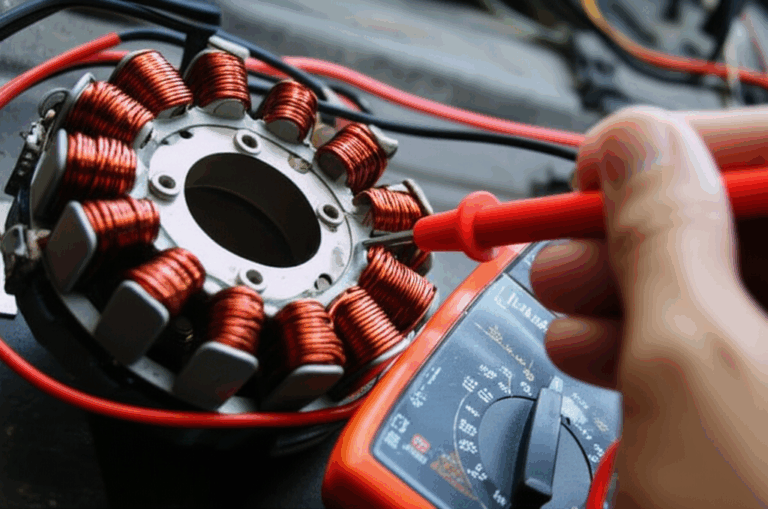
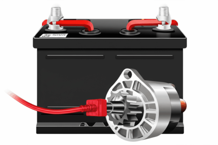
Let’s level set. The stator is the stationary set of copper windings inside your ATV engine case. The flywheel, which holds permanent magnets, spins around those windings. That spinning magnetic field induces alternating current (AC) in the windings. The voltage regulator/rectifier (often called the R/R) converts that AC to DC and clamps voltage to protect the battery and electronics. If the stator underperforms you see classic symptoms:
- Battery not charging or discharging quickly
- Dim or flickering headlights
- No spark on some systems or a weak spark that causes misfires
- Intermittent electrical issues at certain RPMs
- Burning smell or visual signs of overheated windings
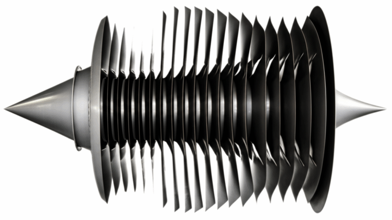
Inside the stator sits a stack of thin electrical steel laminations. Those laminations are not solid for a reason. A changing magnetic field creates eddy currents in metal. Think of eddy currents like little whirlpools in a river. They swirl inside the steel and create heat which wastes energy. Thin, insulated laminations break up those whirlpools which reduces loss and keeps temperatures in check. Better laminations and good assembly practices pay off in higher reliability and more stable charging voltage.
Most modern ATVs use two common stator configurations:
- Single-phase (two-wire stator): Two yellow or white wires from the stator to the regulator
- Three-phase (three-wire stator): Three identical wires which you test in pairs
Your model may use a CDI unit (capacitor discharge ignition) or a different ignition strategy. Always check your service manual for the exact wiring diagram and test points.
Common searches you might recognize line up with the same process we’ll follow: “ATV charging system troubleshooting,” “how to check ATV magneto,” “regulator rectifier testing ATV,” “multimeter settings for stator test,” “stator AC output voltage,” “open circuit stator test,” “short circuit stator diagnosis,” “how to test a 3 phase stator,” and “stator wire color codes.” We’ll cover these, then we’ll go deeper into stator core lamination choices that reduce failure rates.
Essential Tools for Stator Testing
You don’t need a lab. You do need a few basics.
- Digital multimeter that can measure AC volts and low ohms
- Basic hand tools to access connectors and remove covers
- The ATV’s service manual for specs and wiring diagram
- Optional: Flywheel puller if you must remove the flywheel for visual inspection
- Safety gear: gloves and eye protection
- Clean rags and contact cleaner for dirty connectors
Set your multimeter to AC Volts (ACV) for output testing and Ohms (Ω) for winding integrity and continuity tests. If your meter has range settings use 200 VAC for AC tests and the lowest ohms range for resistance checks.
Safety First: Precautions Before You Begin
- Disconnect the battery negative terminal before you unplug charging connectors.
- Set the ATV on a level surface and secure it. You do not want it lurching when you start it for an AC voltage test.
- Keep hands clear of moving parts. Watch for hot engine parts.
- Route your test leads safely. You don’t want them tangled in the flywheel or the fan.
Preliminary Checks: Rule Out Other Issues
Before you chase the stator, verify the basics. This avoids misdiagnosis and wasted parts.
- Battery health: Measure battery voltage after a full charge and a rest period. 12.6 VDC or higher suggests a healthy, fully charged battery. A deeply discharged battery can mimic stator problems.
- Wiring harness integrity test: Inspect the charging circuit harness end to end. Look for frayed insulation, loose terminals, green corrosion, or broken connectors.
- Voltage regulator/rectifier quick check: Look for burnt smells or melted potting. Heat sink damage or discolored wiring can indicate failure. A faulty R/R can overload a stator which accelerates stator failure.
- Grounding: Verify clean, tight grounds from the frame and engine case. A bad ground can cause battery voltage fluctuations and intermittent electrical problems.
Step-by-Step ATV Stator Testing Procedures
You’ll run three core tests:
- Visual inspection
- AC voltage output test
- Resistance and ground tests
Follow the sequence. It rules out most failure modes on ATVs from Honda, Yamaha, Polaris, Kawasaki, Suzuki, Can-Am, Arctic Cat, Kymco, and others. Always compare your values to the service manual. Specs vary by engine size and design.
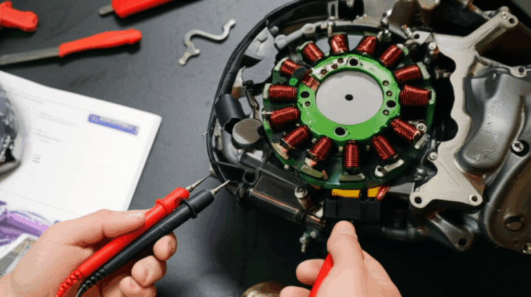
Method 1: Visual Inspection (If Accessible)
Many stators live under a side cover with the flywheel. Some models let you remove the cover without pulling the flywheel which makes inspection easier.
- Remove the stator cover if the design allows it without a full teardown.
- Look for burnt windings, melted insulation, swollen epoxy, or dark discoloration.
- Inspect the grommet where the stator wires exit the case. Oil ingress or chafing at this point is common.
- Check the connector pins for pitting or heat damage.
Obvious heat damage usually points to an overload or a short to ground. It may also hint at low oil or contaminated oil which reduces stator cooling.
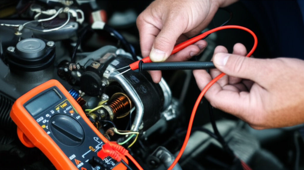
Method 2: AC Voltage Output Test (Stator Power Generation)
This test tells you if the magneto is actually generating power.
1) Locate the stator wires
- Find the two or three stator leads that run to the regulator/rectifier. They are often yellow or white.
2) Disconnect from the R/R
- Unplug the stator leads from the R/R. You must isolate the stator to measure its output.
3) Set multimeter
- Set your meter to ACV. If it has ranges choose 200 VAC.
4) Two-wire stator test
- Place your meter leads on the two stator wires.
- Start the ATV. Let it idle. Record AC voltage at idle.
- Raise RPM to 3,000–5,000 RPM as spec allows. Record ACV again.
5) Three-wire stator test
- Test each pair: 1 to 2, 1 to 3, and 2 to 3.
- Record all three readings at idle and at the specified RPM.
6) Interpret results
- Many systems show 20–70+ VAC at idle and significantly higher at elevated RPM. Your manual will specify acceptable ranges.
- All three pairs on a 3-phase stator should be similar. Big differences point to a bad phase.
If you measure AC voltage from any stator wire to engine ground you should see near zero. A noticeable AC voltage to ground suggests a short to the engine case.
Method 3: Resistance/Continuity Test (Winding Integrity)
Do this with the engine off and the stator unplugged from the R/R.
1) Set multimeter
- Switch to Ohms on the lowest range.
2) Two-wire stator
- Touch the leads to the two stator wires. Record resistance.
3) Three-wire stator
- Measure 1–2, 1–3, and 2–3. Record each value.
4) Interpret results
- Typical readings fall between 0.1 and 1.0 ohms. The exact value depends on the design and wire gauge.
- Inconsistent resistance between phases suggests a partial short or a heat damaged winding.
- An “OL” reading or very high resistance means an open circuit which is a broken winding.
Method 4: Stator Ground Test (Short Circuit Check)
This checks for a short to the engine case.
1) Set multimeter
- Use the lowest Ohms range.
2) Test procedure
- Place one meter lead on a clean, unpainted engine ground.
- Touch the other lead to each stator wire one at a time.
3) Interpret results
- A good stator shows no continuity to ground on any lead. Your meter may display “OL” or a very high number.
- Any low resistance reading means a short to ground which is a failed stator. Replace it.
These tests mirror common search intents like “Ohm test ATV stator,” “continuity test ATV wiring,” “testing stator wires to ground,” and “stator output measurement.” They also tell you when to look elsewhere such as the voltage regulator test or the ignition coil testing on systems where charging and ignition share elements.
Interpreting Your ATV Stator Test Results
- Good stator
- AC voltage meets the manual spec at idle and increases with RPM. Resistance between stator wires is low and consistent. No continuity from any stator wire to ground. You likely have an R/R or wiring issue.
- Bad stator with an open circuit
- AC voltage is low or zero. Resistance between one pair reads “OL.” Visual inspection may show a burnt or broken winding.
- Bad stator with an internal short
- AC output is significantly lower than spec. Resistance between one pair is lower than the others. You see uneven heating or dark spots.
- Short to ground/case
- Any continuity from a stator wire to engine ground is an immediate fail. Replace the stator.
Correlate symptoms to your findings. Battery drain and dim headlights point to low system voltage which aligns with low stator output. Intermittent issues at certain RPMs can indicate partial shorts that get worse with heat. A burning smell usually means the insulation broke down.
What to Do If Your ATV Stator Is Bad
In most field cases you replace a failed stator. Repairing a stator winding is possible in specialized shops yet it rarely makes sense on a cost or time basis for typical ATVs. When you choose a replacement consider:
- OEM vs aftermarket
- OEM stators match the original output and usually meet durability expectations. Aftermarket stators vary in quality.
- Match specs
- Confirm the phase type, connector style, resistance values, and AC output ranges.
- Address root cause
- Test the regulator/rectifier. Replace it if suspect since an overcharging R/R can cook a new stator. Check oil level and condition. Oil cools the stator in many designs.
Equipment designers and procurement teams should look beyond the part number. The durability of the stator ties back to lamination quality and heat management. If your fleet sees recurrent failures consider a deeper look at lamination materials and manufacturing processes. That’s where we shift to the engineering fundamentals.
Design Insight: Why Laminations Matter in Stators
Let’s connect field failures to the physics inside the stator core. A stator core uses a stack of thin electrical steel sheets called laminations. Each sheet is insulated from the next. This stack forms the magnetic path that guides flux from the rotor magnets through the teeth and back around the yoke. The core’s job is to carry magnetic flux with minimal loss.
Two main loss mechanisms dominate:
- Eddy current loss
- Changing magnetic fields induce currents inside conductive steel. Those currents create heat. Thinner laminations with good insulation block the formation of large eddy loops which reduces heat.
- Hysteresis loss
- As the magnetic field reverses, the material expends energy to flip its magnetic domains. This shows up as a loop on the B-H curve. Materials with low coercivity reduce hysteresis loss.
A simple analogy helps. Eddy currents act like whirlpools in water. Laminations turn one big whirlpool into many tiny ripples which dissipate less energy. Magnetic permeability acts like the spongeiness of the steel to magnetic flux which is similar to how a sponge soaks up water. A high-permeability core lets flux pass easily which boosts performance and reduces magnetizing current.
Why designers care:
- Cooler operation means longer insulation life on the copper windings.
- Lower core loss improves charging efficiency which reduces fuel consumption in engine-driven power systems.
- Stable magnetic properties across temperature help keep output consistent at idle and at high RPM.
- Better steels allow thinner sections which reduce weight without sacrificing performance.
If you spec or buy stators you want to know what steel you are getting, how it was cut, and how the stack was joined. You also want a supplier who understands how process heat can degrade magnetic properties.
For a high-level overview of the building blocks see this guide to motor core laminations. It shows how stator and rotor stacks come together.
Material Considerations for Motor Core Laminations
Material selection drives performance and cost. Here’s a balanced overview you can use during design reviews or sourcing.
- Non-oriented silicon steel (NOES)
- These are silicon alloyed electrical steels with roughly equal magnetic properties in all directions. They are the workhorse for rotating machines. Grades differ by core loss and thickness. Thinner gauges reduce eddy currents at higher frequencies. Standards like ASTM A677 and the IEC 60404 series define properties and test methods.
- Pros: Good availability and cost. Suitable for single and three-phase stators in ATVs and general motors. Balanced performance across directions.
- Cons: Higher core loss than the best grain-oriented steels at very low frequencies. Not needed for transformer-like applications inside motors since flux rotates.
- Grain-oriented silicon steel (GOES)
- GO steels align grains for superior magnetic performance along one direction. You see these in transformers where flux stays aligned with the rolling direction. GO is less common for rotating stators.
- Pros: Very low loss along the grain direction. Great for transformer lamination core designs.
- Cons: Anisotropic which limits usefulness in rotating machinery. Cutting across the grain can increase loss.
- High-silicon and low-loss grades
- Premium NOES grades with tighter chemistry and coating control reduce core losses further. These help in high-output or high-temperature stators.
- Pros: Lower loss which keeps winding temperatures down. Good for high RPM or high-load duty.
- Cons: Higher material cost.
- Cobalt-iron alloys
- Used when you need high saturation flux density which allows more power density. Think aerospace or racing EV motors.
- Pros: Exceptional performance and high saturation. Useful for very compact or high-torque designs.
- Cons: Expensive and tougher to machine. Not typical for cost-sensitive ATVs.
If you want to refresh the basics of the base material family see this resource on electrical steel laminations. It outlines silicon steel families and their behavior.
Coatings and insulation matter just as much:
- Organic or inorganic coatings on each sheet provide interlaminar insulation which cuts eddy currents. They must withstand stamping and heat during stack assembly.
- The choice affects punchability, weldability, and bonding. It also influences the final core loss because poor coating uniformity creates local eddy hotspots.
Thickness is your thermodynamic lever:
- Thinner laminations reduce eddy current loss because the loop area shrinks. They also increase manufacturing cost and can challenge stamping due to burr control.
- Thicker laminations cost less and stamp easily. They run warmer at the same flux swing.
In short, you balance cost, core loss, manufacturability, and stack height. That balance depends on the duty cycle of the engine and the target charging output across the RPM band.
Manufacturing and Assembly Processes That Shape Performance
You can pick a great steel and still get a mediocre stator core if the manufacturing process adds loss or causes defects. Here’s what to watch.
- Cutting method
- Progressive die stamping
- Best for high volume with consistent quality. Tooling cost is higher up front. Good die design controls burrs which protects interlaminar insulation.
- Laser cutting
- Excellent for prototypes and complex shapes with tight tolerances. It introduces a heat-affected zone which can raise local loss if not controlled.
- Wire EDM and waterjet
- Useful for very small runs where thermal effects must be minimized. Slower and more expensive per part.
- Stack assembly methods
- Interlocking
- Tabs on adjacent laminations lock like LEGO bricks. No welding required which preserves magnetic properties. Great for thin sheets where welding might overheat edges.
- Bonding
- Adhesives join laminations to create a rigid stack with excellent vibration behavior. Adhesive selection must respect thermal cycles and oil exposure.
- Welding
- Spot or seam welds hold stacks. Excessive heat raises loss near the weld and can damage coatings. Welding patterns should avoid high flux regions.
- Burr control and deburring
- Burrs bridge insulation layers which creates unintended shorts between laminations. That raises eddy currents and heat. You want low burr height and clean edges.
- Stress relief and coatings
- Mechanical stress from stamping increases loss. Some processes include stress-relief annealing for certain steels. Coating integrity after cutting and assembly keeps interlaminar resistance high.
- Dimensional and stack height control
- Consistent tooth width and slot geometry maintain flux uniformity which reduces hotspots and noise. Good stack height control keeps air gaps tight which stabilizes performance.
These process choices also relate to rotor stacks. The rotor experiences similar magnetic and thermal realities. If you are reviewing a complete assembly consider the influence of the rotor core lamination on overall efficiency and noise.
For stator-specific design variations including tooth shapes and yoke thickness see this overview of stator core lamination. Small geometry tweaks can change flux paths, copper fill factor, and thermal behavior.
Which Application Is This For? Matching Materials and Processes to Use Cases
Your best choice depends on duty cycle, operating environment, and production volume. Use this section as a decision aid.
- ATV and powersports charging stators
- Typical frequency is tied to engine RPM and pole count. You care about performance at idle plus adequate headroom at high RPM. Non-oriented silicon steel with a sensible thickness gives you a low-loss core without high cost. Interlocking or bonding avoids weld heat in stator teeth. Good oil flow and oil cleanliness matter because oil cools the stator in many engines.
- If you see repeated overheating review lamination thickness and core loss grade. You might step down a thickness or step up to a lower loss NOES grade.
- BLDC and high-efficiency e-mobility stators
- Higher electrical frequencies and tighter thermal limits push you to thinner laminations and premium low-loss grades. Bonding and careful burr control reduce loss and acoustic noise. For topology and stack options review a focused example of a bldc stator core.
- High-volume industrial motors
- Stamping with interlocking or welding remains the economic choice. Tooling amortizes over volume. You can afford better steels in higher efficiency tiers because energy savings pay back the premium.
- Transformer and stationary magnetic cores
- For transformers you switch to grain-oriented steels and EI or UI formats which align flux with the rolling direction. Those choices don’t apply to rotating ATV stators yet they illustrate why application fit matters.
Honest trade-offs:
- Laser cutting shines for prototypes and complex designs with low volume. It costs more per part and can add a heat-affected zone that increases loss. Stamping wins in cost and consistency for production runs if you maintain burr and stress control.
- Bonding improves vibration behavior and keeps interlaminar resistance high. It adds process steps and adhesive validation.
- Interlocking is fast and avoids weld heat. It needs good die control to prevent tab-induced distortion or stress.
How Field Failures Link Back to Design
The failure modes you measured in the ATV tests map directly to core and winding realities.
- Open circuit in a winding
- Usually a broken conductor or a failed solder joint at a terminal. Heat cycling and vibration accelerate it. High core loss heats the winding which shortens insulation life. Reduce core loss to lower winding temperature.
- Internal short in the winding
- Insulation breakdown between adjacent turns. Heat and contamination push the insulation over the edge. Improving cooling and reducing loss helps.
- Short to ground/case
- Damaged insulation at the slot or grommet lets a conductor touch the stator core or engine case. Burrs or sharp edges in the lamination stack can worsen abrasion. Better deburring and slot liner integrity mitigate this.
- Overheating and discoloration
- Heat is the enemy. Overload from a failed regulator/rectifier forces the stator to supply maximum current constantly which drives losses in both copper and core. Low oil level or contaminated oil reduces cooling. High core loss grades run hotter. Choose a lower loss steel and control lamination thickness to reduce eddy current heat.
Practical Example: A Diagnostic Walkthrough With Real-World Numbers
You test a three-wire stator on a Yamaha Grizzly. At idle you measure 28 VAC between each pair which is consistent. At 4,000 RPM you see 68–70 VAC across all pairs. Resistance checks show 0.6–0.7 ohms on each pair. No continuity to ground. That stator passes. The ATV still won’t charge, so you test the voltage regulator/rectifier output to the battery. You see unstable DC at idle that drops as you add electrical load which points to a bad R/R. Replace the R/R and confirm 14.2 VDC at the battery at 3,000 RPM.
Second case. On a Honda Foreman you see 6 VAC between one pair at 3,000 RPM yet 40–45 VAC on the other pairs. Resistance on the bad pair reads 0.1 ohm which is significantly lower than the other pairs. You also measure 3–4 VAC from the bad phase to ground. That stator has a partial short and a short to the engine case. Replace the stator and inspect the grommet for chafing.
Use these as patterns for Polaris RZR, Kawasaki Brute Force, Suzuki KingQuad, Can-Am Outlander, or Arctic Cat models. Specs vary yet the physics does not.
Common Questions From Teams Balancing Design And Cost
- How do lamination thickness and grade affect stator output at idle
- Thinner and lower-loss laminations reduce core loss which keeps winding temperature down. Cooler copper has lower resistance which helps voltage under load at idle. The core itself doesn’t “create” voltage yet it reduces waste which improves system headroom.
- Do we need cobalt alloys in powersports
- Rarely. Cobalt helps when you chase power density and saturation limits in compact high-performance motors. Most ATV charging stators run well with NOES grades that balance cost and loss.
- Is laser cutting ok for production
- It works for low to medium volume with complex geometries. Control the heat-affected zone and validate core loss against stamped parts. If the HAZ penalty is small and you avoid tooling cost you can win on total cost.
Sourcing Tips For Procurement Managers
- Request material certificates that reference applicable standards like IEC 60404 test methods and ASTM A677 for NOES grades. Review core loss values at specified flux density and frequency.
- Ask for edge burr height measurements and deburring practices. Burr control protects interlaminar insulation which cuts eddy currents.
- Confirm stack assembly method and rationale. Interlocking vs bonding vs welding each carry performance and cost impacts.
- Audit sample parts for dimensional consistency at teeth and slots. Tight geometry improves copper fill and reduces localized saturation.
- Validate the manufacturing route for the lamination blanks and for the stack. Cutting method and stack joining both affect loss and mechanical integrity.
If you want a broader snapshot of offerings across formats and grades scan the catalog of motor core laminations and compare against your target duty cycle and volume.
Quick Reference: Terms You’ll See
- AC Voltage (ACV): Alternating current voltage generated by the stator
- Ohms (Ω): Electrical resistance unit used in the winding integrity test
- Continuity: A closed electrical path which shows as low resistance
- OL: “Open loop” or over limit on a meter which indicates no continuity
- CDI: Capacitor discharge ignition unit used in some ATV ignition systems
- Permeability: How easily magnetic flux passes through a material like water through a sponge
- Coercivity: A material’s resistance to being demagnetized
- Eddy Currents: Circulating currents in metal induced by changing magnetic fields which create heat
- Hysteresis Loss: Energy lost flipping magnetic domains as the field reverses
Troubleshooting Checklist You Can Print
- Battery voltage after charge and rest ≥ 12.6 VDC
- Clean and tight grounds to frame and engine case
- Stator unplugged from the R/R for all tests
- AC Voltage between stator wires:
- Two-wire: meets spec at idle and rises with RPM
- Three-wire: all pairs match within tolerance
- No measurable AC voltage from any stator wire to ground
- Resistance between stator wires:
- Low and consistent between pairs
- No continuity from any stator wire to ground
- Visual inspection:
- No burnt windings, melted insulation, or damaged grommets
- If stator passes yet charging fails:
- Test regulator/rectifier DC output to battery
- Inspect wiring harness and connectors end to end
Trust Signals And References
Use recognized standards and test methods when you evaluate materials and suppliers.
- IEC 60404 series: Magnetic materials and test methods for magnetic properties
- ASTM A677: Standard specification for non-oriented electrical steel, fully processed types
- ASTM A343/A343M: AC magnetic properties test methods at power frequencies
- ISO 9001: Quality management systems for manufacturing control
I avoid specific proprietary data or unpublished case studies. The test values and failure modes in this guide align with common manufacturer service manuals and standard repair practices across brands.
The Business Case: Why This Matters To Design And Procurement
A good diagnostic saves you from swapping parts blindly. A better stator core saves you from buying the same part twice. When field tests point to overheating or repeated failures you should treat the problem as a system:
- Validate regulator/rectifier behavior since it can overload the stator.
- Review oil cooling pathways and contamination control.
- Revisit stator lamination grade and thickness. Lower loss material and thinner laminations reduce heat.
- Confirm manufacturing steps that control burrs, assembly stress, and insulation integrity.
Measure. Compare to spec. Adjust your design or sourcing strategy so the next stator runs cooler and lasts longer.
Your Engineering Takeaway
- Start with the stator AC voltage test then confirm resistance and ground isolation. Compare against the service manual. This quickly separates stator faults from R/R or wiring issues.
- Heat drives most stator failures. Overload from a bad regulator, low oil cooling, high core loss, or shorts all trace back to temperature.
- Lamination material and thickness matter. Thinner sheets with good insulation cut eddy currents which lowers core loss and reduces winding temperature.
- Manufacturing details count. Stamping quality, burr control, interlocking or bonding, and weld heat all influence magnetic loss and reliability.
- Match materials and processes to your application. Use NOES for typical ATV stators, premium low-loss grades for high-output or high-frequency machines, and laser cutting only when the economics and loss targets line up.
If you design or source stators and want a deeper dive into geometry choices, process trade-offs, and material options browse these primers on stator core lamination, electrical steel laminations, and bldc stator core. Use them to prepare sharper questions for your supplier and to benchmark your current design.
When you test a stator on the bench you solve a problem today. When you choose better laminations and processes you prevent the same problem tomorrow. That’s how you improve uptime, cut warranty claims, and build machines you trust.