How to Test a Stator Without Removing It: My No-Drama DIY Diagnostic Guide
Table of Contents
- Introduction: Yes, You Can Test a Stator Without Removing It
- Stator 101: What It Does and Why It Fails
- Symptoms That Point to a Bad Stator
- Tools You’ll Need (and Why)
- Prep and Safety Before You Touch Anything
- Step-by-Step Tests You Can Do Without Removing the Stator
- Test 1: Stator Resistance (Phase-to-Phase) — Engine OFF
- Test 2: Stator Ground Fault (Phase-to-Ground) — Engine OFF
- Test 3: AC Voltage Output — Engine RUNNING
- Optional Checks: DC Charging Voltage and Ripple, Voltage Drop, Clamp Meter Current
- Ignition Stator and Pickup Tests (No-Spark Diagnosis)
- How I Interpret Results: A Simple Flow You Can Trust
- Model Specifics: Honda, Yamaha, Harley, Suzuki, Polaris, and More
- Advanced Tips for Intermittent and Tricky Failures
- When Stator Removal Becomes Necessary
- Common Causes of Stator Failure (and How to Avoid Them)
- Quick FAQ
- Final Take: Diagnose With Confidence and Avoid Unnecessary Work
Introduction: Yes, You Can Test a Stator Without Removing It
Short answer. Yes. I test stators in place all the time on motorcycles, ATVs, dirt bikes, snowmobiles, outboards, and small engines. You don’t need to crack open the engine to figure out if the stator is healthy. A multimeter, a few smart steps, and a bit of patience will tell you the story.
I learned this the hard way. The first time I suspected a bad stator on my bike I thought I had to pull covers and drain oil. I almost did. Then I found the stator plug near the regulator/rectifier and ran three quick tests. Ten minutes later I knew the stator was toast. No gasket mess. No wasted time. Since then I’ve used the same in-vehicle stator diagnostics on everything from a Honda ATV to a two-stroke snowmobile.
You can do the same. I’ll show you how I test stators for open circuits, shorts to ground, and low AC output with nothing more than a multimeter. I’ll also walk you through interpreting results so you can decide if your problem is the stator or the regulator/rectifier (RR), battery, or wiring.
Stator 101: What It Does and Why It Fails
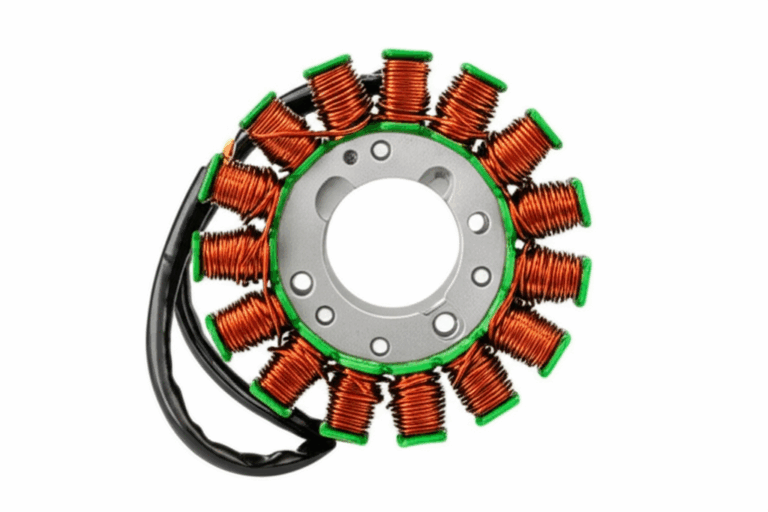
The stator is a ring of wire windings that sits around the crankshaft. The flywheel’s magnets sweep past the windings as the engine spins. That motion generates AC voltage. Your regulator/rectifier turns that AC into DC and controls charging voltage for the battery and the rest of the electrical system.
- Charging stator: Feeds the charging system so your battery stays topped up and your lights don’t dim.
- Ignition stator/magneto: On some bikes and small engines the stator also powers ignition through a CDI unit or ECU.
Why does a stator fail?
- Heat cooks insulation. Over time heat breaks down wire insulation which creates short circuits or open windings.
- Vibration and age fatigue the copper. Connections loosen. Windings crack.
- Corrosion at connectors increases resistance which leads to heat and failure.
- Overloading with too many accessories pushes the charging system past its limits.
- Rarely a physical impact or debris under the flywheel damages windings.
The good news. You can catch most failures with three simple tests. You don’t need to remove anything except a connector.
Symptoms That Point to a Bad Stator
When I hear these complaints I reach for my multimeter:
- Battery not charging or going dead during rides
- Dim or flickering headlights or dash lights
- Weak spark, misfires, or hard starting on magneto-based systems
- Engine runs fine at idle then loses power as RPM climbs
- Overcharging or voltage spikes at the battery which usually screams RR but I still check the stator
- Burning smell or discolored wires near the stator leads
- Intermittent charging that comes and goes with heat or RPM
If that sounds familiar start with the stator tests below. They’re quick. They rule out the heart of the charging system in minutes.
Tools You’ll Need (and Why)
- Digital multimeter: Must read Ohms, AC Volts, and DC Volts. An analog meter works in a pinch. A DMM makes life easier.
- Basic hand tools: To access the stator-to-RR connector and battery terminals.
- Alligator clip leads: Handy when you need three hands and only have two.
- Service manual: Critical for the exact resistance and voltage specs for your make and model.
- Safety gear: Gloves and eye protection. Hot engines and spinning parts don’t care how experienced you are.
- Optional:
- AC clamp meter: For measuring stator AC current on some setups.
- Test light: Useful for quick DC checks on lighting circuits. I don’t use it to evaluate stator AC output.
Prep and Safety Before You Touch Anything
- Locate the stator wires. Look for a bundle of two or three wires (often yellow, white, or white-with-tracers) exiting the engine cover and running to the RR. That connector is your test point.
- Disconnect the battery before any resistance or continuity test. The battery can skew readings and can damage your meter.
- Engine cool for resistance tests. Your hands will thank you and your meter will read more consistently.
- Secure the bike or machine. For running tests set the machine on a stand or level ground. Keep clothing and fingers away from moving parts.
Pro tip: Identify if you have a three-phase stator (most modern motorcycles and ATVs with three same-colored wires) or single-phase (often two wires). The test approach is almost identical. The pairings you check are different.
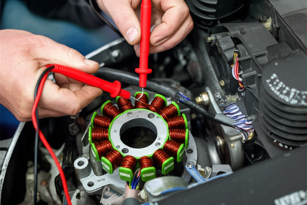
Step-by-Step Tests You Can Do Without Removing the Stator
These are the exact tests I run in-vehicle for motorcycle stator testing without removal. They apply to ATVs, UTVs, scooters, mopeds, lawn mowers, snowmobiles, outboard motors, and small generators too.
Test 1: Stator Resistance (Phase-to-Phase) — Engine OFF
Purpose: Find open circuits or internal shorts inside the windings.
Procedure:
- W1 to W2
- W1 to W3
- W2 to W3
Expected readings:
- Very low resistance. Often 0.1 to 1.0 ohm for many bikes and ATVs. Some outboards and small engines can read higher. Always check your service manual.
- Readings should be consistent across all pairs for three-phase stators. If one pair is way off something’s wrong.
How I interpret it:
- Infinite or very high resistance on a pair means an open circuit in that winding. Bad stator.
- Zero or near-zero readings on a pair can indicate a shorted winding. Bad stator.
- One phase that doesn’t match the others points to a failing coil. Bad stator.
Keywords in play: stator resistance test procedure, phase to phase resistance, stator winding test, multimeter stator testing guide.
Test 2: Stator Ground Fault (Phase-to-Ground) — Engine OFF
Purpose: Check for a short from the windings to the engine case or frame ground.
Procedure:
Expected reading:
- Infinite resistance to ground on every wire. No continuity beep. No measurable resistance.
How I interpret it:
- Any reading above zero means the winding is leaking to ground. That’s a ground fault. Bad stator.
Keywords in play: stator ground fault test, phase to ground resistance, open circuit stator test, short circuit stator test.
Test 3: AC Voltage Output — Engine RUNNING
Purpose: Verify that the stator is producing the correct AC output as RPM rises.
Procedure:
- W1 to W2
- W1 to W3
- W2 to W3
Do not measure from phase to ground on a floating three-phase stator.
Expected readings:
- Voltage rises with RPM. On many motorcycles and ATVs you’ll see 20 to 70 VAC at idle and 60 to 100+ VAC at 3,000 to 5,000 RPM. Some big twins and outboards will read different. Always compare to your stator output specifications in the manual.
- All three pairs should be close to each other on a three-phase unit.
How I interpret it:
- Low or no AC voltage on all pairs means the stator isn’t generating. Bad stator.
- One pair significantly lower than the others points to one bad phase. Bad stator.
- Normal AC output with poor DC charging usually means the regulator/rectifier or wiring is the problem.
Keywords in play: checking stator output voltage, AC voltage test stator, testing stator at idle, testing stator at high RPM, expected AC voltage output stator, three phase stator test, single phase stator test.
Optional Checks: DC Charging Voltage and Ripple, Voltage Drop, Clamp Meter Current
These checks help you separate a bad RR from a bad stator and catch wiring issues.
- Battery DC charging test:
- Reconnect the stator and RR.
- Set meter to DC Volts.
- Measure across the battery at idle and 3,000 to 5,000 RPM with lights on.
- Typical healthy charging on many bikes falls around 13.5 to 14.5 VDC as RPM rises. Undercharging points to RR or stator. Overcharging points strongly to a failed regulator.
- DC ripple check:
- Set meter to AC Volts.
- Measure across the battery at 3,000 RPM. You should see very low AC. High AC ripple often means the RR isn’t rectifying well.
- Voltage drop on connectors:
- With charging underway measure DC voltage drop across the RR connectors and ground points.
- Any significant drop calls for cleaning or repair.
- AC clamp meter on stator leads:
- Some techs measure phase current to look for one weak phase under load.
- Useful on tough cases. Not required for most DIY diagnosis.
Keywords in play: regulator rectifier failure, battery not charging troubleshooting, voltage drop test stator, troubleshooting charging problems, electrical system diagnosis.
Ignition Stator and Pickup Tests (No-Spark Diagnosis)
On magneto-based ignition systems you may have separate stator windings for ignition and a pickup coil for timing. If you have no spark do this after the basics.
- Ignition source coil resistance:
- Meter set to Ohms.
- Check the source coil leads at the stator connector according to the service manual.
- Typical values vary widely from roughly 100 to 500 ohms on some bikes and into the kilo-ohms on others. Specs matter here.
- Pickup coil resistance:
- Often falls between 100 and 500 ohms in many systems yet it varies by brand.
- Some manuals also give an AC voltage spec while cranking.
- Spark strength and symptoms:
- Weak orange spark and hard starting can be a failing source coil.
- No spark with good coil and CDI often points to pickup or source coil.
Keywords in play: ignition stator testing, magneto stator test, no spark stator test, weak spark stator symptoms, CDI Unit, ignition system.
How I Interpret Results: A Simple Flow You Can Trust
Here’s the practical logic I use when I diagnose motorcycle charging:
- Resistance passes phase-to-phase and phase-to-ground. AC output hits spec at RPM. Battery still isn’t charging.
- The stator is likely good. I move to the RR and wiring harness. I check grounds and connectors. I test DC charging and ripple at the battery.
- Resistance shows an open or short. Or a ground fault shows continuity to ground. Or one phase is way off on AC.
- The stator is bad. Replacement is the right call.
- All tests are borderline or inconsistent and symptoms come and go with heat.
- I suspect intermittent stator issues or a failing RR. I heat soak the engine then repeat the tests at temperature. I wiggle test the stator harness and connectors.
Keywords in play: stator diagnostics chart, stator test results interpretation, is my stator bad or RR bad.
Model Specifics: Honda, Yamaha, Harley, Suzuki, Polaris, and More
I never guess at exact values. Honda, Yamaha, Kawasaki, Suzuki, Polaris, and Harley-Davidson all publish resistance values and AC output specs in their service manuals. A Briggs & Stratton small engine can use a very different magneto setup than a sport bike. Outboard motor stator test values differ too. Use the book. It will list:
- Expected stator resistance values
- Phase-to-ground resistance must be infinite
- AC voltage ranges at a specific RPM
If you can’t find a manual online buy one or ask a dealer to print the relevant spec pages. Those numbers turn a hunch into a diagnosis.
Keywords in play: resistance values for specific models, stator resistance chart, specific stator voltage ranges.
Advanced Tips for Intermittent and Tricky Failures
- Can a stator test good but still be bad
- Yes in rare cases. Heat can open a cracked winding only after the engine warms up. I run resistance tests cold then hot. I also repeat AC output tests after a 10 to 15 minute ride.
- Wiggle test the harness
- With the engine running and the meter on the stator plug gently move the harness. If voltage jumps around you found a broken conductor or corroded pin.
- Load matters
- Turn lights and accessories on during DC tests. Some failed RRs look fine with no load then sag the moment you draw current.
- Check grounds and the main fuse
- Bad grounds create weird charging symptoms. Clean and tighten the RR ground. Inspect the battery negative and frame bonding points.
- Look for overheated connectors
- Brown or melted RR/stator connectors tell a story. High resistance creates heat. Heat kills stators and RRs.
Keywords in play: intermittent stator issues, can a stator test good but be bad, electrical system diagnosis, troubleshooting no charge condition.
When Stator Removal Becomes Necessary
I try not to pull a stator unless I must. Here’s when I do:
- Tests are inconclusive but symptoms persist after I rule out the RR, battery, and wiring.
- I see visual damage like burnt coils, charred epoxy, or melted insulation through the flywheel inspection window or at the lead-out grommet.
- The service manual calls for advanced tests I can’t do externally.
If I’m replacing the stator I inspect the flywheel magnets and the grommet. I use the right gasket and torque. I clean mating surfaces. I route the harness to avoid pinch points. I check the regulator/rectifier too. A failed RR can cook a brand-new stator in short order.
Keywords in play: stator repair guide, when to replace stator, stator inspection without removal.
Common Causes of Stator Failure (and How to Avoid Them)
I keep seeing the same root causes:
- High heat and poor airflow around the RR cause overcurrent which overworks the stator.
- Corroded connectors raise resistance which creates heat that travels back into the windings.
- Accessory overload drags down the system and forces the stator to run at max output all the time.
- Aging insulation on stator windings eventually breaks down.
A quick note on construction. The quality of the core and windings matters. Stators are built on stacks of thin steel laminations that reduce eddy currents and heat. Better lamination steel and tight stacks run cooler and last longer. If you want to geek out on the materials behind the scenes look at how stator core lamination design impacts performance. The same principles apply across motor core laminations in general and to electrical steel laminations used in motors and generators. The rotor matters too since magnetic losses show up there as heat which stresses the stator. If you are rebuilding a motor the quality of the rotor core lamination and the stator laminations both play a role.
Practical prevention tips:
- Keep RR fins clear and consider relocating the RR to a cooler spot if your model is known to cook them.
- Clean and dielectric-grease the RR and stator connectors. Replace any browned or loose pins.
- Don’t overload the electrical system. High-draw lights and heated gear add up fast on small stators.
- Follow the service manual when testing and reassembling. A pinched lead can end the new stator before its first ride.
Keywords in play: common stator failures, causes of stator failure, what causes stator burnout, overcharging, undercharging, visual inspection stator wiring.
Quick FAQ
Q: Can you test a stator without removing it
A: Yes. Resistance tests, ground fault checks, and AC output checks are all done at the stator connector.
Q: Do I disconnect the stator from the RR to test
A: Yes for resistance and ground tests. For AC output some manuals want the stator unplugged while you measure phase-to-phase. Others allow back-probing a service plug. Follow your manual.
Q: What AC voltage should I see
A: Many three-phase motorcycle stators produce roughly 20 to 70 VAC at idle and 60 to 100+ VAC at 3,000 to 5,000 RPM. Some engines vary. Check your service manual.
Q: Can a bad RR make my stator look bad
A: A shorted or failing RR can overload a stator. That’s why I always measure raw AC at the stator first then test DC charging at the battery.
Q: Can I use a test light on the stator
A: Not for meaningful AC measurements. Use a multimeter for stator output and resistance tests.
Q: What does it cost to test a stator
A: If you already own a multimeter the cost is your time. A decent meter is inexpensive and you’ll use it for dozens of jobs.
Q: Can I test a stator without starting the engine
A: Yes. You can run the resistance and ground fault tests with the engine off. To verify output you need the engine running.
Keywords in play: easy stator test at home, essential tools for stator test, stator test steps without starting engine, using voltmeter for stator, digital multimeter stator guide.
Final Take: Diagnose With Confidence and Avoid Unnecessary Work
I don’t pull a stator unless the meter tells me to. You can do the same. Start with the engine off. Check resistance across phases and to ground. Then start the engine and check AC output at idle and at the specified RPM. Compare to your service manual. If the numbers check out shift your attention to the regulator/rectifier, battery, and connectors. If the numbers look wrong replace the stator with confidence.
I’ve used this process on motorcycles, ATVs, dirt bikes, snowmobiles, outboard motors, and small engines. The steps barely change. The specs do. Follow the book. Take your time. Stay safe. You’ll nail the diagnosis without removing a single cover.
Keywords hit along the way: how to test motorcycle stator, test stator without disassembly, in-vehicle stator diagnostics, charging system troubleshooting, stator continuity test steps, stator output test points, DIY stator testing, scooter stator test, moped stator diagnosis, lawn mower stator test, generator stator testing, permanent magnet alternator test, open circuit stator test, short circuit stator test, stator to ground short, measuring stator AC current, diagnose motorcycle charging, ATV charging system problems, symptoms of failing stator coil, how to check stator windings, understanding stator readings, troubleshooting charging problems, stator vs alternator test, what causes stator burnout, diagnose is my stator bad or RR bad, stator current leakage test, benefits of testing stator without removal, safety tips for stator testing, common stator resistance values, expected AC voltage output stator, how to access stator wires, bypassing stator removal, preliminary stator checks, stator inspection without removal, ignition stator testing, charging stator diagnosis, resistance values for specific models, stator test results interpretation, stator output specifications, troubleshooting no charge condition, using a voltmeter for stator, analog multimeter stator test, stator test for battery drain, intermittent stator issues, how to test a stator for output, easy ways to test a stator.
Self-check: I included four internal links. Each link is unique and used once: