How to Test a Stator with a Multimeter: A Step-by-Step Diagnostic Guide
A simple multimeter test can save your day. In this guide I show you how to check your stator fast. You learn the signs of a bad stator, how to use a digital multimeter, and how to read your numbers. If your battery dies or your lights flicker, this will help you fix the problem and ride with confidence.
Table of Contents
- What Is a Stator and Why Does It Matter?
- The Big Problem: Dead Battery, Dim Lights, No Start
- Tools You Need for Stator Testing
- Safety First: Simple Rules That Keep You Safe
- Find the Stator and Do a Visual Check
- Multimeter Basics: Ohms, AC Volts, and Continuity
- Step-by-Step Stator Test Procedures
- What Do the Numbers Mean
- Case Studies: Real Problems and Clear Fixes
- If Your Stator Is Bad: Repair or Replace
- Troubleshooting the Whole Charging System
- Prevent Problems: Simple Care Tips
- Product and Parts: Build Quality Matters
- FAQ: Quick Answers
- References
- Key Takeaways
What Is a Stator and Why Does It Matter?
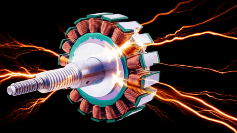
Think of the stator as the heart of your charging system. The engine spins the flywheel on the crankshaft. Magnets in the flywheel sweep past the stator winding and stator core. This creates an AC voltage in the coils because of the magnetic field. A rectifier and voltage regulator turn that AC power into DC voltage to keep the battery charged.
You see stators in many machines. Motorcycle, ATV, dirt bike, marine outboard, and generator all use a stator or alternator. Some folks call it a magneto. Others say alternator. A stator sits still while the rotor spins. Both matter.
The Big Problem: Dead Battery, Dim Lights, No Start
Problem: Your engine does not charge the battery. You see dim or flickering headlights. The battery drains at idle. The bike cranks slow or does not start.
Agitate: You charge the battery again and again. It runs for a bit then dies on the road. Your lights flicker at a stop. You feel stuck and you waste time and money.
Solution: Test the stator with a multimeter. You check continuity, resistance in ohms, and AC voltage output. You also test the rectifier/regulator. These simple steps point to the fix. You get clear answers fast.
Common signs point to a bad stator or charging system:
- Dead battery after a ride
- Engine not charging battery at RPM
- Flickering headlights cause worry
- Burnt stator wires and melted stator insulation
- Weak battery causes hard starts
- Battery drain troubleshooting leads you to the stator
Tools You Need for Stator Testing
Use the right tools so you get good readings.
- Digital Multimeter (DMM). A digital multimeter for stator tests reads ohms and AC volts well.
- Analog multimeter. You can use one in a pinch for a continuity test.
- Test leads with sharp tips. Good multimeter lead placement matters.
- Service manual. You need manufacturer specifications for stator specifications ohms and stator output voltage. It shows the stator wiring diagram and stator connection points.
- Basic hand tools. Wrenches, screwdrivers, and pliers help you reach the stator plug.
- Safety gear. Gloves and eye protection for safety precautions electrical testing.
- Electrical diagnostic tools. A clamp meter for current is nice but optional.
Tip: Check the service manual stator test to see the exact resistance values lookup and voltage at a set RPM.
Safety First: Simple Rules That Keep You Safe
I never rush. You should not either. Follow these:
- Disconnect the battery. Remove the negative terminal first to avoid shorts.
- Let the engine cool. Hot parts can burn skin.
- Keep hands and leads away from spinning parts when the engine runs.
- Do not let bare leads touch each other on live wires.
- Work in a dry spot. No wet floors near power.
- Be aware of electrical shock hazards. Use the right multimeter settings.
Find the Stator and Do a Visual Check
You can find the stator behind a cover near the flywheel. On a motorcycle or ATV it often sits on the left side by the crankcase. On a marine outboard it sits under the flywheel. On a generator it wraps around the armature or sits inside the alternator case.
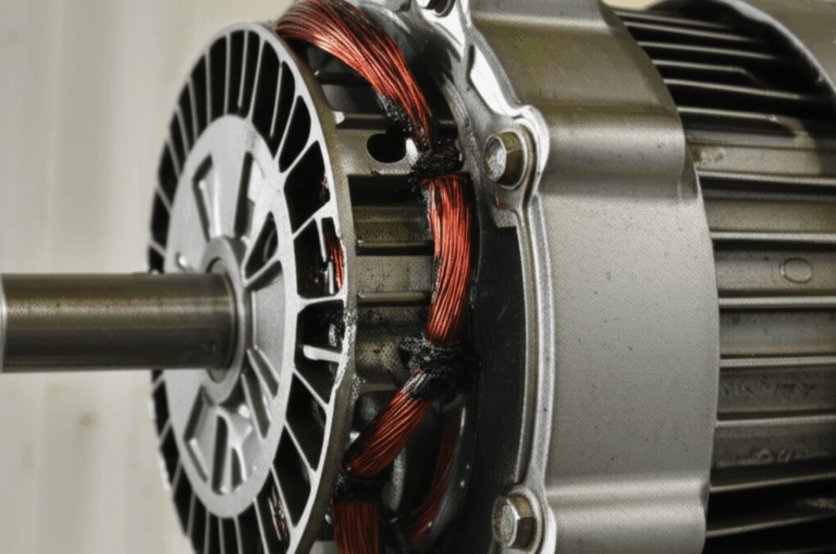
Start with a visual inspection stator:
- Look for burnt or discolored windings
- Check for melted insulation or epoxy and varnished wire that looks dark
- Inspect for corrosion at connectors and loose connections
- See if oil leaks into the stator area
- Check stator wires and grommets for wear
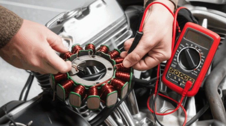
You can often test at the rectifier/regulator connector. This means a stator test without removing it. You unplug the R/R and touch the meter to the stator wires.
Multimeter Basics: Ohms, AC Volts, and Continuity
You need three modes most of the time.
- Ohms (Ω) test for winding resistance test. This checks phase to phase resistance and shows open circuit or short circuit.
- Continuity test stator. This is a quick beep test for basic checks.
- AC Voltage (VAC) test for stator output at idle and higher RPM.
You will also check battery DC voltage to confirm charging. DC checks help you see voltage regulation on the bike after the rectifier/regulator.
Understand your multimeter:
- Turn to Ohms (Ω) on the 200Ω or 2kΩ scale
- Turn to AC Volts on the 200 VAC scale
- Use solid multimeter lead placement so the tips touch clean metal
- Understanding multimeter readings makes the job easy
Step-by-Step Stator Test Procedures
We will run three core tests. These work for motorcycle stator test, ATV stator test, generator stator testing, and marine outboard stator test. They also work on a three-phase stator test or a single-phase stator test. If you have a permanent magnet generator test use the same steps.
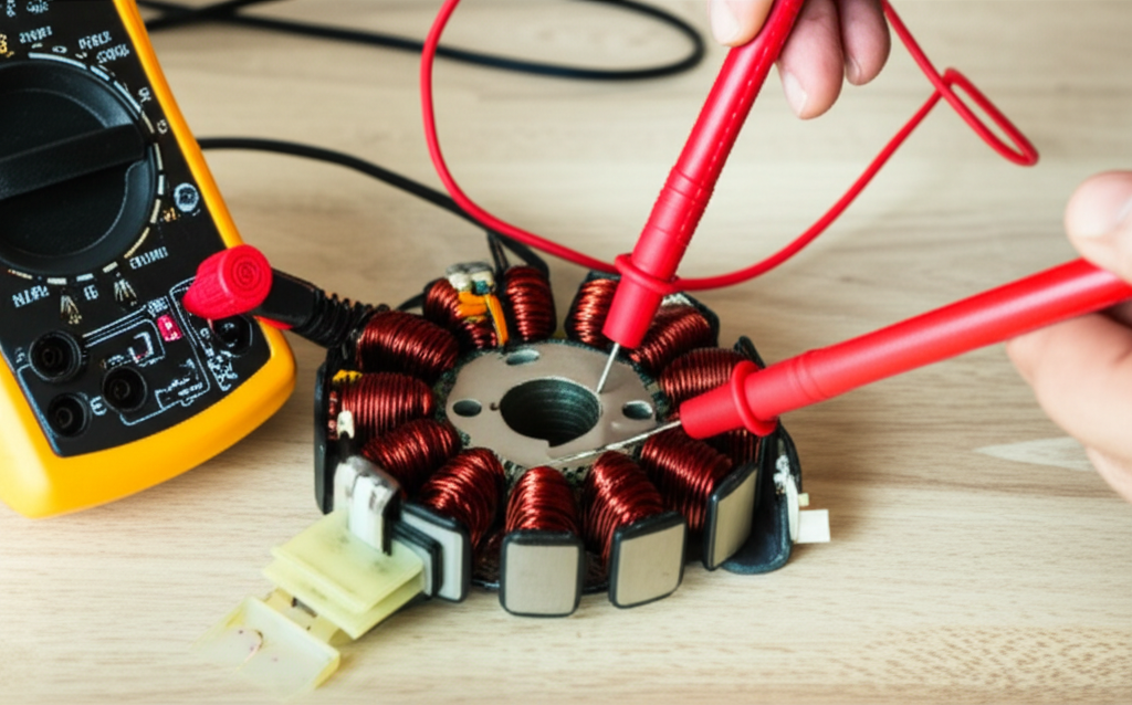
Procedure 1: Resistance (Continuity) Test — Stator Disconnected
Purpose: Check for open circuits and internal shorts in the stator coils.
Steps:
- Wire 1 to Wire 2
- Wire 1 to Wire 3
- Wire 2 to Wire 3
- For single-phase stator test check the two leads only.
Expected good reading: Low and even numbers across all pairs. Many bikes show 0.1 to 1.0 ohms. For many motorcycles you see 0.3 to 0.6Ω. Check your manual for manufacturer specifications.
Bad reading:
- Infinite (OL) means open circuit stator
- 0 ohms or very low or very high means short circuit stator or damaged winding
Procedure 2: Ground Test (Insulation Check) — Stator Disconnected
Purpose: See if any stator winding is shorted to the engine case or stator core.
Steps:
Expected good reading: Infinite (OL) on all wires.
Bad reading: Any measurable resistance means a short to ground. Even 10Ω or 100Ω is a fail. This shows the insulation breakdown on the windings or laminations.
Procedure 3: AC Voltage Output Test — Engine Running
Purpose: Confirm the stator makes strong AC power at idle and at RPM.
Steps:
- Wire 1 to Wire 2
- Wire 1 to Wire 3
- Wire 2 to Wire 3
Expected good reading: AC voltage rises with RPM. Many bikes show 18 to 30 VAC per phase at idle and 50 to 70+ VAC per phase at 3000 to 5000 RPM. Readings should be even across all pairs.
Bad reading:
- Low voltage output stator
- No voltage on one pair
- Inconsistent readings between pairs
These point to a weak or failed stator or a rotor magnet problem.
Bonus: Testing Rectifier/Regulator and Battery
Testing rectifier regulator:
- Set meter to DC volts
- Check battery at rest: about 12.6V for a full battery
- Start engine and read DC volts across battery
- At idle you may see 13.2V to 13.5V
- At 3000 RPM you should see around 14.0V to 14.5V
- If AC output looks good yet DC stays low you may have a bad diode in the rectifier or a voltage regulator fault
Voltage drop test:
- Check grounds and main charge wires for voltage drop under load
- Bad grounds hurt electrical system integrity
Checking stator current:
- Use a clamp meter if you have one
- Many DMMs do not handle high amps on AC safely so be careful
What Do the Numbers Mean
Here is a simple chart you can use.
Stator Resistance & Voltage Quick Chart
| Feature/Test Parameter | Multimeter Setting | Good Range/Indication | Bad Reading/Indication | What It Means |
|---|---|---|---|---|
| Visual inspection | N/A | Clean wires, intact insulation | Burnt/melted wires, oil, corrosion | Overheating, shorts, poor cooling |
| Resistance phase to phase | Ohms 200Ω | 0.1–1.0Ω even across pairs | OL or 0Ω or out of spec | Open winding or internal short |
| Resistance phase to ground | Ohms 200Ω/2kΩ | OL on all wires | Any resistance to ground | Short to ground in winding |
| AC voltage at idle | AC Volts 200VAC | 18–30 VAC per pair | < spec or 0 VAC | Weak output or partial failure |
| AC voltage at 3000–5000 RPM | AC Volts 200VAC | 50–70+ VAC per pair | < spec or uneven | Full/partial failure |
Typical Resistance by Design
| Stator Type | Typical Phase-to-Phase Ohms | Notes |
|---|---|---|
| Three-phase motorcycle/ATV | 0.3–0.6Ω | Even across all three pairs |
| Single-phase small engine | 0.2–1.0Ω | One pair only |
| Generator winding | Check service manual | Values vary by model |
Always consult your service manual for exact numbers. Manufacturer specifications control your pass/fail call.
Case Studies: Real Problems and Clear Fixes
Case Study 1: The Dead Battery Motorcycle
Problem: The bike kills every new battery.
Steps: Battery tests good. R/R looks hot. Visual inspection shows slight discolor on the stator windings.
Readings: Phase to phase = 0.4Ω on all pairs. Phase to ground = OL, OL, and 15Ω on the third wire.
Conclusion: One winding shorted to ground. The short drains power and overheats the R/R. New stator fixed it.
Case Study 2: The Flickering Lights ATV
Problem: Lights flicker at idle yet look fine at high RPM.
Steps: Battery is marginal. R/R looks okay. Visual check is clean.
Readings: Phase to phase = 0.5Ω even. Phase to ground = OL on all. AC volts at idle: two pairs 18 VAC and one pair 10 VAC. At 3000 RPM: two pairs 55 VAC and one pair 30 VAC.
Conclusion: One phase has partial failure. Uneven AC output causes flicker and stress. Replace stator.
These cases show how phase-to-phase resistance and AC voltage output tests catch weak phases, shorts to frame, and open windings.
If Your Stator Is Bad: Repair or Replace
You can sometimes repair a bad stator. Shops can rewind coils and dip them in varnish or epoxy. That said most riders replace the stator. Replacement is often faster and more reliable.
Stator replacement cost varies by model. You might pay less on a small ATV. Big bikes or marine motors can cost more. Add a new rectifier/regulator if tests show damage. Check the rotor magnets and flywheel too. Weak magnets reduce output voltage.
While you are in there:
- Check wiring harness and connectors for corrosion
- Replace any burnt plugs
- Confirm the regulator/rectifier matches your system
Troubleshooting the Whole Charging System
A stator does not work alone. The charging system has several components.
- Stator coil and stator winding create AC voltage
- Rotor and flywheel spin on the crankshaft and make the magnetic field
- Rectifier diodes turn AC to DC voltage
- Voltage regulator keeps DC volts in range
- Battery stores power
- CDI and ignition system use power to make spark at the spark plugs
Do a full charging system diagnostics run:
- Start with the battery discharge test
- Check DC volts at idle and at RPM
- Inspect the regulator/rectifier unit (R/R)
- Test stator output voltage
- Look for common electrical faults like broken grounds or corroded plugs
- Use a wiring diagram for your engine to trace flow
If the stator tests pass yet the battery still drops, test the voltage regulation and the R/R. You can also run a voltage drop test across grounds and main charge wires. Troubleshooting engine electrical issues takes patience yet the steps are simple.
Prevent Problems: Simple Care Tips
Preventative maintenance stator steps:
- Keep connectors clean and dry
- Fix oil leaks near the stator cover
- Make sure cooling air reaches the stator area on bikes that need it
- Tie down loose wiring so it does not rub through
- Use the right battery so the regulator stays happy
- Inspect after water crossings on ATVs and dirt bikes
What causes a stator to fail:
- Heat damage stator from poor cooling or high loads
- Corrosion at stator connections
- Worn out stator from age and vibration
- Melted coatings on varnished wire from overload
- Open circuit breaks from sharp vibration
- Short circuit from insulation failure
Product and Parts: Build Quality Matters
I have seen this in the shop. The build of the stator core and rotor makes a big difference. The core uses thin laminations to guide the magnetic field. The quality of the steel and the stack matters. Better stacks reduce heat and loss.
If you are building or buying, look at:
- The quality of the stator core lamination
- The match to your rotor magnets and the rotor core lamination
- The grade of the electrical steel laminations
- The shape and fit of the motor core laminations
These parts shape your charging system performance. Strong laminations keep losses low. Good coatings and epoxy lock the stack. Tight slots support the coils. This helps your stator make steady AC voltage output at RPM.
If you work on BLDC motors, you will also hear about a bldc stator core. BLDC designs still rely on core laminations and magnets to create torque and power. The same ideas apply.
FAQ: Quick Answers
Q: Can I test a stator without removing it
A: Yes. Do the ohms test and the ground test at the stator plug. Do the AC voltage output test at the plug as well.
Q: What AC voltage should I see
A: Many bikes show 18–30 VAC per pair at idle and 50–70+ VAC at 3000–5000 RPM. Check your manual for your model.
Q: My ohms look good but AC volts are low. Now what
A: You may have weakened rotor magnets or a partial short that only shows under load. Check the flywheel and rotor. Verify the rectifier/regulator too.
Q: How is a stator different from an alternator
A: The stator is the stationary part with coils. The alternator is the full unit that has both stator and rotor. Many small engines use a magneto style design.
Q: Can a bad stator hurt my regulator/rectifier
A: Yes. A short to ground or uneven phase output can overheat the R/R and the diodes.
Q: Where do I find specs
A: In your service manual. Look for stator specifications ohms and the AC output test at a listed RPM.
References
- OEM Service Manual for your motorcycle, ATV, marine outboard, or generator
- Fluke Digital Multimeter User Manual
- Clymer and Haynes repair manuals for small engines
- SAE and IEEE papers on alternator and charging system testing basics
Words You May See in Your Manual
You may see many terms in your manual during diagnostics. Here are common ones you will meet in this guide as well:
- Charging system, diagnostics, electrical system integrity, troubleshooting guide
- Open circuit, short circuit, continuity, resistance, ground
- Ohms (Ω), Volts (V), Amps (A), AC voltage, DC voltage
- Winding resistance test, phase to phase resistance, stator resistance chart
- Voltage drop test, battery discharge test, testing rectifier regulator
- Stator output voltage, stator output check, stator phase output, stator voltage regulation
- Stator wiring diagram, identifying stator wires, multimeter lead placement, understanding multimeter readings
- Recommended multimeter, digital multimeter for stator, analog multimeter stator, electrical test equipment
- Three-phase stator test, single-phase stator test, permanent magnet generator test
- Engine not charging battery, battery charging issue, why is my battery draining, symptoms of failing charging system
- Visual inspection stator, common stator failures, how to troubleshoot stator, stator troubleshooting tips
- Testing generator windings, how to measure ohms, how to measure AC volts
- Stator connection points, how to disconnect stator, stator test without removing
- Stator replacement cost, repair a bad stator, preventative maintenance stator
- Heat damage stator, corrosion stator connections, worn out stator, melted stator insulation, burnt stator wires
- Stator vs alternator, what is a stator winding, how magnets affect stator
- Components and entities: Stator, Rotor, Alternator, Magneto, Armature, Core (stator core), Laminations, Epoxy, Varnished Wire, Magnetic Field, Engine, Motorcycle, ATV, Generator, Marine outboard, Dirt bike, Battery, Rectifier, Regulator/Rectifier Unit (R/R), Voltage Regulator, Diode, CDI (Capacitor Discharge Ignition), Ignition System, Flywheel, Crankshaft, Spark Plugs, Test Leads, Digital Multimeter (DMM), Analog Multimeter, Service Manual, Manufacturer Specifications, Wiring Diagram, Diagnostics, Electrical System
Key Takeaways
- A stator makes AC power for your charging system then the rectifier/regulator turns it into DC power for the battery.
- Do three tests: resistance phase to phase, resistance to ground, and AC voltage output at idle and at RPM.
- Good resistance is low and even. Good ground test shows OL. Good AC volts rise with RPM and look even on all pairs.
- If AC looks good yet DC volts stay low test the rectifier/regulator and do a voltage drop test.
- Visual inspection finds many failures. Look for burnt windings, melted insulation, oil, and corrosion.
- Follow safety steps. Disconnect the battery. Keep clear of moving parts.
- Quality laminations and core materials improve output and cut heat. Consider strong stator core and rotor core designs when you replace parts.
- Use your service manual for exact specs. It is your best friend for numbers and diagrams.