How to Test a Stator Pickup Coil: A Hands-On Guide From My Garage
Table of contents
- Understanding the pickup coil’s job in your ignition
- Tools I actually use for pickup coil testing
- Safety and prep before you turn a wrench
- Step-by-step: Static resistance test (ohms)
- Step-by-step: Dynamic AC voltage test (engine cranking)
- Typical specs and what good readings look like
- Two-wire vs three-wire pickup coils
- If the pickup coil tests good, what’s next
- Common symptoms and what they really mean
- Why pickup coils fail and how I prevent repeat failures
- Pro tips that save time and headaches
- Replacement advice: OEM vs aftermarket
- Construction matters: stator and rotor notes you should know
- Quick answers to common questions
- Conclusion: Test with confidence
Understanding the pickup coil’s job in your ignition
When a motorcycle, ATV, dirt bike, small engine, or outboard has no spark or intermittent spark, I rarely guess. I start with the pickup coil test. You’ll also hear it called a pulser coil or trigger coil. Different names same job. It sends a timing pulse to the CDI (capacitor discharge ignition) or ECU telling the ignition coil exactly when to fire the spark plug.
Here’s the simple picture. A magnet on the flywheel or rotor swings past the pickup coil. That changing magnetic field induces a small AC signal in the pickup coil. The CDI sees that pulse and discharges into the ignition coil which then dumps high voltage into the spark plug. If the pickup coil can’t deliver a clean pulse you’ll chase your tail with plugs and coils and still get no spark.
Some signs push me to test the pickup coil right away:
- No spark while cranking
- Intermittent spark that comes and goes with heat or vibration
- Hard starting after warm-up
- Misfire at certain RPMs that aren’t fuel related
- Weak or mistimed spark on engines with CDI
I see the same story on many brands: Honda, Yamaha, Kawasaki, Suzuki, KTM, Husqvarna, Polaris, Mercury Marine outboards, even small engines like Briggs & Stratton and Kohler. The principles don’t change and the test steps don’t either.
Tools I actually use for pickup coil testing
You don’t need a lab. You need the right basics and a steady hand.
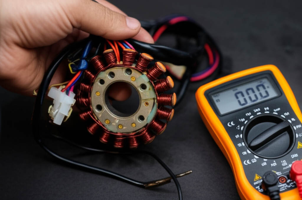
- Digital multimeter with Ohms (Ω) and AC Volts (VAC). I prefer a meter with a low AC range and fast update rate. An analog multimeter can work for resistance checks and sometimes shows pulsing better during cranking.
- Vehicle-specific service manual. This is critical for wire colors, connector locations, and exact pickup coil resistance specifications.
- Basic hand tools. Sockets, screwdrivers, hex keys to access connectors or side covers.
- Back-probing pins or thin probes. They keep you from stabbing insulation and creating future problems.
- Wiring diagram. Helps identify pickup coil wires versus stator charging wires.
- Optional: Oscilloscope. Great for catching weak or noisy trigger pulses during intermittent faults.
- Optional: Feeler gauge. For checking air gap between pickup coil and flywheel trigger if manual specifies one.
Safety and prep before you turn a wrench
I keep this simple and safe.
- Disconnect the battery on systems where you could short something while probing. If you need to crank during a dynamic test reconnect the battery for that step only.
- Work on a cool engine. You’ll avoid burns and your resistance readings will be more consistent.
- Secure the machine. Neutral on bikes. Lanyard off or safe mode on outboards. Stand clear of moving parts when cranking.
- Find the pickup coil connector. The pickup sits near the flywheel or stator under the engine cover. Its wires usually exit the engine case in a small harness that leads to the CDI/ECU connector.
- Confirm wire colors in the manual. Manufacturers love color codes but they don’t all match. Don’t guess.
Step-by-step: Static resistance test (ohms)
This is the fastest way to catch an open or shorted pickup coil.
1) Isolate the pickup coil. Unplug the pickup coil connector so the coil isn’t connected to the CDI or the rest of the harness. That isolation prevents false readings.
2) Set your multimeter to Ohms. If your meter doesn’t auto-range start around 200 Ω or 2 kΩ depending on your service manual.
3) Measure across the pickup coil leads. Touch one probe to each pickup coil wire. Don’t press hard or pierce the insulation.
4) Interpret the reading.
- In-spec resistance: Good sign. Many motorcycle and ATV pickup coils read somewhere between about 50 Ω and 300 Ω. Some small engines land anywhere from roughly 20 Ω to 1 kΩ. Your manual wins every time.
- OL or Infinity: Open circuit. That usually means a broken internal wire or a failed solder joint inside the epoxy potting.
- 0 Ω or extremely low: Shorted winding. That coil won’t generate a usable pulse.
5) Check for a short to ground. Put one probe on a pickup coil wire and the other on a clean engine ground. You should see OL open circuit. Any measurable resistance to ground points to a shorted wire or insulation failure.
6) Consider temperature. Resistance climbs with heat. If the bike dies only when hot I test cold then again at operating temp. I’ve caught many intermittent coils this way.
A quick story. I had a Yamaha trail bike that would run for 10 minutes then die like someone flipped a kill switch. Cold resistance measured 210 Ω which sat dead center of spec. I idled it on a fan for 15 minutes and repeated the test hot. Resistance jumped to 420 Ω which sat way above the manual’s range and the bike had no spark when hot. New pickup coil fixed it.
Step-by-step: Dynamic AC voltage test (engine cranking)
If the resistance test passes I want to see if the coil actually generates a pulse.
1) Reconnect or back-probe. Plug the pickup coil back into the harness if the CDI needs to “see” the signal under normal load. I slide thin back-probe pins alongside the terminals to read voltage without damaging the connector.
2) Set the meter to AC Volts. Choose a low AC range if the meter isn’t auto-ranging. Many signals fall between about 0.5 and 5 VAC while cranking.
3) Crank the engine. Use the starter. On pull-start engines give consistent pulls. Keep your hands and sleeves clear.
4) Read the AC voltage between the two pickup coil leads. You want to see a fluctuating AC value while the flywheel moves. Don’t test to ground unless your manual specifies a grounded-return style.
5) Interpret the result.
- You see about 0.5 to 5 VAC that rises with cranking speed: That’s a healthy sign. The exact voltage isn’t critical across models. I care more about a clear, stable pulse that scales with RPM.
- You see 0 VAC or a tiny random number that doesn’t change with speed: Suspect a failed pickup coil, broken wire, bad connector, wrong air gap, or a weak/damaged flywheel magnet.
An oscilloscope makes this test shine. A good pickup coil produces a clean, predictable pulse. Noise or flat spots on the waveform point to wiring issues or a failing coil that a meter might miss.
Typical specs and what good readings look like
Service manuals provide exact numbers and you should follow them. That said I’ll share the ranges I see most often.
- Resistance for many motorcycles and ATVs: roughly 50–300 Ω
- Resistance for many small engines and outboards: roughly 20–1000 Ω
- AC voltage while cranking: about 0.5–5.0 VAC measured across the coil leads
- Open circuit shows OL or Infinity on the meter
- Short circuit shows 0 Ω or a very low value
Cranking speed matters because the pickup coil is an AC generator. A weak battery can produce a weak signal which can confuse diagnosis. I charge the battery and use a strong starter so I don’t chase ghosts.
Two-wire vs three-wire pickup coils
Most pickup coils have two wires. You measure resistance and AC voltage across those two leads. Some systems use a three-wire setup. Why?
- A shared ground or shielded ground line to the ECU
- Dual pickup sensors in one housing for multiple cylinders or timing modes
- A separate reference wire for the ECU on some models
If you see three wires don’t guess at which two to test. The service manual will map them. I’ve seen folks measure between a signal and a shield which yields odd results. You want signal-to-signal on a dual-signal coil or signal-to-ground when the manual says so.
If the pickup coil tests good, what’s next
You ruled out the pickup coil. Good. Here’s how I continue a no-spark or weak-spark diagnosis.
- Test the stator charging coils. On CDI systems the stator’s high-voltage source coil charges the CDI’s capacitor. You’ll check AC voltage output from the stator while cranking and you’ll compare it to the manual’s spec.
- Test the CDI or ignition module. You can’t open a CDI and fix it but you can confirm power in and trigger out with a scope or a peak-voltage adapter. Many manuals offer CDI test trees.
- Test the ignition coil. Measure primary and secondary resistance. Check for carbon tracking on the case. Inspect the spark plug cap and its internal resistor for cracking or high resistance.
- Check the spark plug and the plug gap. An incorrect gap can mimic weak ignition. I use a spark tester so I’m not guessing with a loose plug on the head.
- Inspect the wiring harness and grounds. Corrosion and loose grounds create maddening intermittent faults. I tug lightly on connectors. I look for green copper and heat discoloration. I verify the ground wire and engine case share a solid bond.
- Verify kill switch and safety interlocks. On bikes I check the kill switch and ignition switch. On ATVs I check neutral and brake interlocks. On outboards I check the lanyard switch. A faulty kill circuit can sink a good trigger signal.
Common symptoms and what they really mean
I match symptoms to likely culprits so I don’t waste time.
- No spark at all: Pickup coil could be dead. Stator source coil could be dead. CDI could be dead. Kill circuit might be stuck on.
- Intermittent spark that worsens hot: Pickup coil windings can open with heat. CDI can fail with heat. Bad ground connections heat up under load and open.
- Hard start cold with spark present but weak: Check cranking RPM, battery, stator source coil output, and plug gap. A pickup coil that barely registers AC might still show some voltage but fail to trigger reliably.
- Misfire at a specific RPM: Check pickup coil signals on a scope and inspect flywheel magnets for damage or debris. Also confirm plug cap resistance and coils.
Why pickup coils fail and how I prevent repeat failures
I see the same root causes over and over:
- Heat and vibration. Engines cook pickup coils over years of use. The epoxy cracks and the fine wire breaks. Routing the harness to avoid sharp bends and ensuring the pickup isn’t touching the flywheel helps.
- Wire chafing. The harness rubs on a case boss or flywheel and shorts. I use abrasion sleeves and better routing.
- Oil contamination during repair. The coil itself is sealed and oil bath isn’t usually a problem. Oil trapped in connectors is a problem because it attracts dirt and weakens electrical contact.
- Incorrect air gap. If someone replaces a pickup coil and sets the air gap too big you get a weak pulse. Too small and the flywheel can clip the coil at high RPM.
- Flywheel magnet issues. I’ve pulled flywheels that lost magnet strength or had a cracked magnet. A quick test with a screwdriver tells me if the magnet still grips strongly compared to a known good flywheel. Not perfect science but it helps.
- Cheap aftermarket parts. I’ve seen out-of-spec resistance on brand-new parts. Test before you button it up.
“Why does my pickup coil keep failing?” usually traces back to heat, vibration, or harness strain near the grommet. I add a loop of slack and relief so the engine’s movement doesn’t tug the wires. That small change saves future grief.
Pro tips that save time and headaches
- Test cold first then test hot if the symptom appears with temperature. Thermal expansion can open a weak winding.
- Clean your meter leads and the connector pins. I’ve chased phantom resistance that came from dirty tips not a bad part.
- Back-probe. Don’t stab insulation unless you must. If you must seal the puncture with liquid tape or heat shrink.
- Use the right meter range. Pick the lowest AC range that covers a few volts so you can see the pulse.
- Spin the flywheel by hand if you can’t crank. You can get a quick voltage blip with a fast hand spin. A drill on the crank bolt works on some engines if the manual allows it.
- Compare readings between cylinders. Multi-cylinder engines sometimes have multiple pickup coils. A side-by-side reading often exposes the bad actor.
- Keep your battery charged. Low cranking speed makes weak AC signals and weak data.
Replacement advice: OEM vs aftermarket
When the pickup coil fails you’ve got choices.
- OEM parts cost more but match the CDI’s expectations most closely. I prefer OEM for hard-to-diagnose no-spark cases because I want every variable in my favor.
- Aftermarket can work fine. Verify the resistance spec matches your manual. Inspect the potting quality and wire strain relief. If the price seems too good the copper often is too thin.
- Replace the gasket if you pull a cover. A tiny oil leak can spray the stator area and create a mess inside connectors over time.
- Set the air gap per manual. Use a feeler gauge if the spec calls for one. Torque the screws evenly so the pickup stays square to the flywheel.
Cost varies widely by brand. I’ve paid under $30 for simple small-engine pulser coils and well over $100 for certain motorcycle pickups integrated into a stator plate.
Construction matters: stator and rotor notes you should know
Understanding what lives under the cover helps your diagnosis. The pickup coil sits near the flywheel and the stator. The stator itself is wound on a laminated iron core. Those thin iron sheets reduce eddy current losses and keep the magnetic circuit efficient. Better laminations reduce heat which extends the life of everything around them.
If you want a peek behind the curtain, the quality of the stator core lamination affects the stability of the magnetic field the pickup coil senses. The flywheel or rotor matters too. The way the rotor carries magnets and its steel stack-up influence the trigger signal. If you’ve ever wondered what goes into that, this overview of rotor core lamination is a helpful reference.
Big picture, designers pick specific motor core laminations and electrical steel laminations to control losses and magnetic behavior. That’s why some engines produce crisper pickup pulses and tolerate wider air gaps. You don’t need to become a materials engineer but it’s good to know that the metal stack under the windings isn’t just “a chunk of iron.”
Quick answers to common questions
What ohms should a pickup coil read?
- It depends on the engine. Many motorcycle and ATV coils read in the ballpark of 50–300 Ω. Many small engines sit somewhere between roughly 20–1000 Ω. Always check your service manual.
How do I test a pickup coil on a motorcycle?
- Do a static ohms test across the two pickup wires with the coil disconnected. Then do a dynamic AC voltage test while cranking. Expect about 0.5–5 VAC across the leads if it’s healthy. The test applies to street bikes, dirt bikes, and ATVs.
How do I test a 2-wire pickup coil?
- Measure resistance across the two wires with the coil disconnected. Then measure AC volts across the same two wires while cranking. Don’t measure to ground unless the manual says the coil returns to ground.
How do I test a 3-wire pickup coil?
- Identify the correct signal pair using the wiring diagram. Some 3-wire setups use a shielded ground or a dual-signal configuration. Measure resistance and AC volts on the specified pair.
Can a bad pickup coil cause misfire or weak spark?
- Yes. The pickup coil sets timing for the CDI. A weak or noisy signal can cause erratic timing which shows up as intermittent spark, misfires, or hard starting.
What if I get OL on the meter?
- That’s an open circuit. The pickup coil winding likely broke. Replace the coil.
What if I read 0 Ω or near zero?
- That’s a shorted winding. The pickup coil won’t generate a proper pulse. Replace it.
What AC voltage should I see while cranking?
- Around 0.5 to 5 VAC for many systems. You’ll see higher values with faster cranking. The presence and stability of the pulse matters more than the exact number but stay within the manual’s guidance.
Can I test the pickup coil with the engine not running?
- Yes. The static resistance test doesn’t require the engine to run. For the dynamic test you just need the flywheel to move. Use the starter or spin the crank by hand if safe.
How do I check for an open or short in the pickup coil?
- Open shows OL across the leads. Short shows 0 Ω across the leads. Also test each lead to ground. You should see OL to ground on a two-wire isolated coil.
How do I know which wires are for the pickup coil?
- The service manual’s wiring diagram will list wire colors. Pickup coil wires exit the engine alongside stator wires but they use different colors. Don’t mix them up.
What about CDI systems versus ECU systems?
- On traditional CDI systems the pickup pulse triggers the discharge. On ECU-based systems a crank sensor may provide timing and the ECU fires a transistorized coil. Many pulser coil tests are the same in both cases so follow the manual.
How does cranking RPM affect the test?
- Faster cranking produces stronger AC voltage from the pickup coil. A weak battery can make a good coil look bad. Charge the battery and test again.
Should I use an oscilloscope?
- If you can, yes. A scope shows pulse shape and noise. It’s the best way to catch intermittent or borderline signals. A meter still catches most hard failures.
Could the flywheel magnet be the problem?
- It can. If the magnet lost strength or cracked you’ll get weak or no pulses. Compare its “pull” with a known good flywheel. Also check for metal debris stuck to the magnet face.
Can a faulty pickup coil damage the CDI?
- Rarely. Usually the CDI stops receiving a trigger and you get no spark. Short circuits or wiring mistakes can damage electronics though so test carefully.
Do I need to check the air gap?
- If the manual specifies a gap, yes. An incorrect gap weakens the signal. Set it with a feeler gauge.
Does spark plug gap matter here?
- It does. A plug gapped way too wide can mask a healthy ignition trigger because the ignition coil can’t jump the gap under pressure. Always set the gap to spec.
What causes a pickup coil to fail repeatedly?
- Heat, vibration, misrouted harness strain, and poor grounds top my list. Fix the root cause when you replace the coil so you don’t repeat the repair in a month.
Real-world walkthrough: a simple diagnostic path
Here’s how I run the test on a no-spark motorcycle, step by step.
- Verify the easy stuff. Spark plug in good shape and gapped correctly. Kill switch in run. Side stand and clutch interlocks satisfied if present.
- Check for spark with a proper tester while cranking. No spark.
- Measure battery voltage. If it’s weak I charge it because weak cranking produces weak trigger signals.
- Find the pickup coil connector using the manual’s wiring diagram. Disconnect it.
- Static test. Set meter to ohms and measure across the pickup leads. Let’s say I read 220 Ω and the manual calls for 190–250 Ω. Looks good.
- Ground test. Measure from each lead to engine ground. I read OL both ways which is also good.
- Dynamic test. Reconnect the pickup coil. Back-probe the two pickup wires. Set the meter to low AC volts. Crank the engine. I see about 1.8 VAC that bumps to 2.2 VAC with a booster on the battery. Good pulse.
- Move upstream. Check stator source coil output to the CDI. If that’s healthy I suspect the CDI or the ignition coil next.
- Confirm ignition coil resistance and plug cap resistance. If both check out I use a scope to see if the CDI is spitting a high-voltage pulse on the primary when the pickup fires. No pulse means a bad CDI.
That flow keeps me honest and saves me from shotgun parts swaps.
Troubleshooting no-spark by engine type
- Motorcycles and ATVs: Pickup coil and stator live under a side cover. You can test most connectors without pulling the flywheel. Interlocks like side stand and kill switch can add confusion so verify them first.
- Dirt bikes with minimal wiring: The pickup coil test is straightforward and quick. CDI failures are also common on older two-strokes so don’t stop at the pickup coil.
- Small engines and generators: The pulser can be integrated with the stator plate. Hand-spin tests work well here. Many manuals provide a resistance chart for pulser and charge coils.
- Marine outboards: Watch that kill lanyard. It grounds ignition when pulled and will block spark no matter what the pickup does.
A note on measuring tools
I own both digital and analog meters. Digital shines for precise resistance. Analog sometimes makes it easier to “see” a pulsing signal when you crank slowly because the needle bounces. An oscilloscope beats both for dynamic work. If you use a scope, set a sensible time base around crank cadence and trigger on the pickup signal so you can compare pulse height between cold and hot runs.
Don’t forget the wiring
Pickup coil problems often hide in the connectors and the harness. I look for:
- Green corrosion on terminals
- Water intrusion past grommets
- Wires pinched under covers
- Stiff, heat-baked insulation near exhaust runs
- Frayed shielding on three-wire systems
A little dielectric grease on clean terminals keeps moisture out. Don’t slather it. Too much grease insulates rather than protects.
Putting it all together: signals, timing, and spark strength
The pickup coil doesn’t create the spark. It tells the CDI or ECU when to fire. The stator source coil charges the CDI. The ignition coil multiplies voltage. The spark plug jumps the gap. If any piece fails you lose spark. When you test the pickup coil you narrow the hunt to either the trigger or everything else. That’s why I always start here for no-spark and intermittent-spark complaints.
Conclusion: Test with confidence
You can test a stator pickup coil with a multimeter and a method. Start with a static resistance check. Follow with a dynamic AC voltage test while cranking. Compare to your service manual. If the pickup coil passes move on to the stator source coil, CDI, ignition coil, spark plug and wiring. If it fails replace it, set the air gap right, and route the harness with some slack so it lives a long life.
Do the basics well and you’ll fix most no-spark problems without guesswork. I’ve followed this exact process on bikes, quads, outboards, and generators for years. It works.
Internal link self-check: 4 unique internal links used, each only once. Links included: