How to Test a Stator and Rectifier: A Comprehensive DIY Guide to Diagnosing Charging System Issues
If your battery keeps dying or your lights flicker at idle, you’re in the right place. You want a clear method to test a stator and rectifier with a multimeter. You also want to understand what the results say about design choices and long‑term reliability. That’s exactly what this guide delivers. I’ll show you how to measure resistance, AC voltage, and diode function. I’ll translate the readings into practical troubleshooting. Then I’ll explain the engineering fundamentals behind stator cores, laminations, and rectifier design, so you can make smarter decisions whether you’re repairing a motorcycle, selecting components for an ATV, specifying parts for a marine engine, or sourcing parts for a production program.
You’ll walk away with three things:
- A safe, step‑by‑step stator testing procedure and a rectifier testing procedure you can run with a digital multimeter.
- The “why” behind the numbers, including how lamination materials, coil design, and heat management drive performance and failure.
- A practical buyer’s guide to materials, manufacturing processes, and supplier questions, so you can cut risk and cost across your charging system.
Before we dive in, one quick note. Always cross‑check specifications against your OEM service manual because proper stator resistance values and proper rectifier voltage values vary by model.
In This Article
- Understanding Your Charging System: Stator, Rectifier/Regulator, and Symptoms
- Tools and Safety: Multimeter Settings and Setup
- Pre‑Test Diagnostics: Battery, Wiring, and Visual Checks
- How to Test a Stator: Ohms, Ground Shorts, and AC Output
- How to Test a Rectifier/Regulator: Diode and DC Output Tests
- What Your Results Reveal About Core Laminations and Design
- Material Choices and Manufacturing Methods That Matter
- Matching Solutions to Applications: Motorcycle, ATV, Marine, and Automotive
- Real‑World Troubleshooting Scenarios and Interpretation
- After Testing: Repair, Replacement, and Supplier Checklists
- Engineering Takeaways and Next Steps
Understanding Your Charging System: Stator, Rectifier/Regulator, and Symptoms
Let’s start with the basics so the tests make sense.
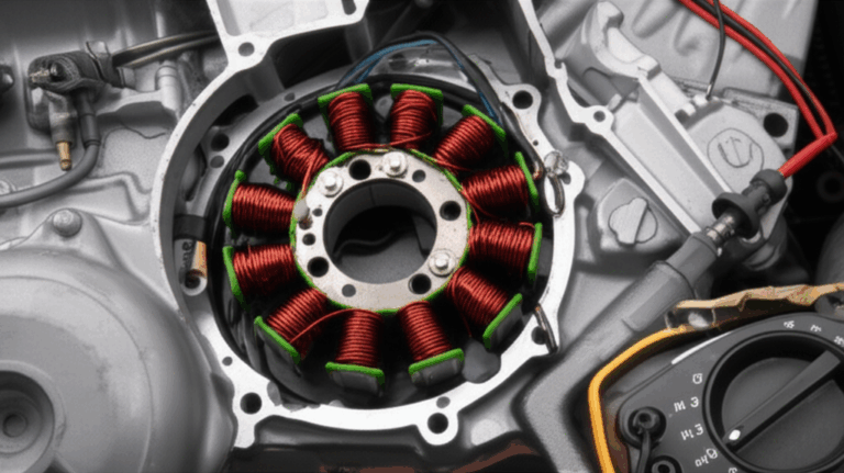
- What is a stator? It’s the stationary coil assembly in your alternator or magneto. Magnets on the flywheel sweep past the stator’s windings. That changing magnetic field induces AC (alternating current) in the windings. The stator is part of the charging system along with the rotor/flywheel, wiring, and battery.
- What is a rectifier and regulator? The rectifier converts AC to DC using diodes or a bridge rectifier. The regulator keeps DC voltage in a safe window for the battery and electronics. Many power units combine both functions as a regulator/rectifier (R/R). Some use shunt regulator design. Others use series regulator design. Either way the R/R manages voltage and heat while providing DC output to the battery.
Common symptoms of a bad stator or rectifier:
- Battery not charging or a dead battery after riding
- Dimming or flickering lights at idle or higher RPM
- Charging system indicator light on
- Engine misfires or erratic running when loads kick on
- Overcharging above 15 VDC which cooks batteries and bulbs
- Undercharging below ~13 VDC which slowly drains the battery
- Intermittent charging problems that come and go with heat or vibration
Why accurate testing matters:
- You avoid the parts cannon. Replace the right component and save time and cost.
- You prevent collateral damage. Overcharging can damage ECUs and lighting. A dying battery can stress the rectifier diodes.
- You inform design and procurement decisions. If a fleet shows repeated stator coil insulation failures or rectifier heat sink issues you can trace root causes back to lamination material choices, coil architecture, and thermal design.
Tools and Safety: Multimeter Settings and Setup
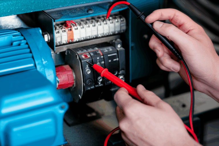
You don’t need fancy equipment to diagnose most charging system issues. A good digital multimeter (DMM) and a few basics will take you far.
Essential tools:
- Digital multimeter with these functions: Ohms (Ω), AC Volts (ACV), DC Volts (DCV), and Diode Test
- Basic hand tools: screwdrivers, wrenches, and pliers to access connectors and components
- Safety gear: gloves and eye protection
- Wiring diagram or service manual: confirm wire colors, connector pinouts, and spec values
- Optional but useful: load tester, test light, oscilloscope for waveform analysis, thermal imaging for hot spots
Multimeter settings you’ll use:
- Ohms for resistance test stator coils and continuity test stator windings
- ACV setting for stator AC voltage output test
- DCV setting for rectifier DC output voltage test
- Diode Check for rectifier diode test
Safety first:
- Work in a ventilated, stable area. Keep loose clothing away from the engine and the flywheel.
- Disconnect the battery when you measure Ohms. You don’t want to backfeed the meter or short the harness.
- Secure connectors. Use insulated leads. High AC from the stator can bite at higher RPM.
Pre‑Test Diagnostics: Battery, Wiring, and Visual Checks
Start here. Simple checks save hours.
- Measure resting voltage after the battery sits for an hour. A healthy 12 V battery reads about 12.6 to 12.8 V. If you see 12.2 V the battery sits partially discharged.
- Perform a load test if possible. Weak batteries cause undercharging symptoms and confuse diagnostics.
- Verify all related fuses and relays. A failed main fuse kills charging.
- Look for voltage drop across connectors. Corroded connectors and ground connection integrity issues create charging system headaches.
- Check the harness and connectors for broken pins, oil ingress, and melted housings.
- Look for burnt wires or discoloration on the stator windings.
- Inspect the rectifier heat sink. Heat marks or a melted casing point to thermal overload.
- Some tests require steady idle speed and stable engine temperature. Follow service manual guidance on RPM for testing.
If the battery fails a load test fix that first. A failing battery drags down the system and can mimic a bad rectifier.
How to Test a Stator: Ohms, Ground Shorts, and AC Output
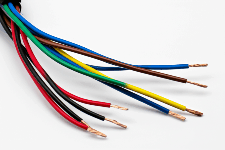
We’ll test a typical two or three‑phase stator found in motorcycles, ATVs, small engines, and marine engines. Always confirm wire count and colors on your machine. Most stators present two or three yellow or white wires as AC outputs.
A. Safety first
- Turn the engine off. Disconnect the battery negative terminal. Separate the stator connector from the harness so you can access stator leads directly.
B. Stator resistance (continuity/Ohms) test
- Set the multimeter to Ohms on the lowest range that comfortably measures near zero ohms.
- Test 1: Winding‑to‑winding resistance
- For a three‑phase stator, test all pairs: A‑B, B‑C, A‑C. For a single‑phase stator, test the two stator leads.
- Expected: low resistance typically 0.1 to 1.0 Ω. Check your manual for proper stator resistance values.
- Interpretation:
- OL or no reading between any pair means an open circuit stator test failure. The winding likely broke.
- Significantly high resistance indicates a failing connection or inter‑winding damage.
- Significantly low compared to spec may indicate an inter‑winding short.
- Test 2: Winding‑to‑ground resistance
- Place one probe on each stator lead and the other on a clean engine ground.
- Expected: Open circuit (OL). The stator windings should not show continuity to ground.
- Interpretation:
- Any resistance reading or continuity means a ground short stator test failure. Replace or rewind the stator.
C. Stator AC voltage output test (engine running)
- Reconnect the battery. Leave the stator disconnected from the rectifier for this test.
- Set the multimeter to AC Volts (ACV).
- Start the engine. Measure AC voltage across each pair of stator leads.
- Perform at idle then at 2000 to 3000 RPM. Many motorcycles show 20 to 70 VAC per phase at higher RPM. Values vary with design so check your manual.
- Voltage should increase with RPM in a smooth way.
- Interpretation:
- Low, inconsistent, or no voltage on a phase indicates a bad winding.
- On a three‑phase stator all three phase‑to‑phase readings should be similar. A significant difference between phases means an unbalanced stator.
D. Interpreting stator test results
- Open winding: OL in Ohms between a pair and low/no AC output on that phase. Replace stator.
- Short to ground: any Ohms reading to ground. Replace stator.
- Inter‑winding short: lower than expected Ohms between phases and reduced AC output. Replace stator.
- Burnt/melted insulation: visible damage usually matches one of the electrical failures above.
If you have an oscilloscope you can perform waveform analysis stator checks. You’ll see three sinusoidal waveforms of similar amplitude and phase spacing on a healthy three‑phase unit. Distorted or clipped waveforms point to coil damage or shorted turns.
How to Test a Rectifier/Regulator: Diode and DC Output Tests
The rectifier turns AC into DC. The regulator keeps the battery happy. We’ll test diodes first then measure system DC voltage.
A. Safety first
- Turn the engine off. Disconnect the battery negative terminal. Disconnect the R/R from the harness so the rectifier sits isolated.
B. Rectifier diode test
- Set the multimeter to Diode Test (diode symbol).
- Identify the R/R input (AC wires from stator) and output (DC positive and ground).
- Using the diode test mode, check each internal diode path:
- Forward bias: place the red lead on the rectifier output positive and black on each stator input lead one at a time. Then test the complementary paths per your unit’s wiring diagram.
- Typical reading: 0.4 to 0.9 V drop. Silicon diodes often land near 0.5 to 0.7 V. Schottky diodes read lower.
- Reverse bias: swap the leads. You should get OL.
- Interpretation:
- A 0.00 V reading in both directions means a shorted diode.
- OL in both directions means an open diode.
- Any inconsistent set of readings across paths points to a bad rectifier.
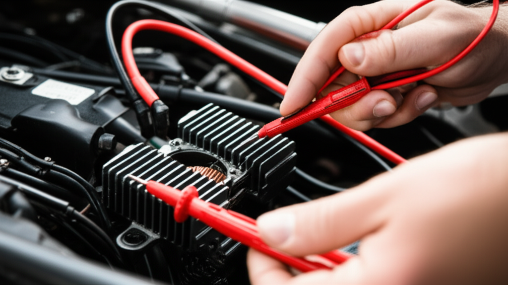
C. Rectifier DC voltage output test (engine running)
- Reconnect the R/R and the battery.
- Set the multimeter to DC Volts (DCV).
- Connect the red probe to the battery positive or the R/R positive output. Connect the black probe to ground.
- Start the engine. Check at idle and at 2000 to 3000 RPM.
- Expected readings:
- Roughly 13.5 to 14.8 VDC with a healthy system, depending on design and temperature.
- The voltage should rise slightly from idle then regulate and stay steady.
- Interpretation:
- Below ~13.0 V across RPM indicates undercharging. Suspect the rectifier/regulator, stator, wiring, or battery.
- Above ~15.0 V indicates overcharging which points to a failed internal regulator in the R/R.
- Erratic voltage swing hints at thermal or connection issues. Check ground integrity and connectors. Then retest.
If your meter supports a ripple test or you have an oscilloscope you can check rectifier output ripple. Excess AC ripple on the DC line often indicates failed diodes or poor connections. High ripple also accelerates battery wear.
What Your Results Reveal About Core Laminations and Design
Testing tells you what failed. Understanding the physics tells you why. That insight helps you fix today’s unit and prevent tomorrow’s callback.
- Eddy currents and core losses: Alternator stators experience changing magnetic fields. If the core were a solid block you’d get large circulating currents inside the metal. Those act like tiny electrical whirlpools that waste energy as heat. Laminations stop those whirlpools. Thin, insulated sheets break the current paths which reduces eddy current loss.
- Hysteresis losses: The iron’s magnetic domains flip back and forth as the magnets pass. That flip costs energy. Materials with lower coercivity, which is the resistance to demagnetization, reduce that cost. Lower hysteresis means less heat and better efficiency.
- Why heat kills charging systems: Heat breaks down stator coil insulation. Heat stresses rectifier diodes and the regulator. Overheating is a major root cause across motorcycles, ATVs, and marine engines. You’ll see it as burnt stator windings, melted potting, scorched R/R cases, or intermittent charging that worsens after a hot soak.
- Lamination material and thickness: Thinner electrical steel with good insulation coating decreases core loss at higher RPM. That means lower operating temperatures and improved reliability. For high‑frequency applications like some BLDC systems you often see thinner gauges to control losses.
For design engineers and procurement teams this matters. A stator that regularly fails insulation resistance tests points to material, stack, or winding issues. A rectifier that runs at its thermal limit points to heat sink sizing, airflow, or load control. Your test data becomes feedback for material selection and manufacturing processes.
If you need a refresher on the building blocks take a look at the breadth of electrical steel laminations. The material choice under the windings weighs heavily on performance.
Material Choices and Manufacturing Methods That Matter
Let’s walk through a practical guide that ties field failures to upstream choices.
Material considerations
- Non‑oriented silicon steels (CRNGO): Most rotating machinery uses CRNGO because it supports magnetic flux in multiple directions. It strikes a good balance of cost and performance for alternators and traction motors.
- Grain‑oriented silicon steel (CRGO): Transformers use CRGO to align grains with the flux path. Alternators rarely use it due to directional sensitivity in rotating fields.
- Silicon content and grade: Higher silicon improves resistivity which cuts eddy current loss. It increases brittleness which affects stamping and handling. Choose grades and thickness based on frequency and flux density targets.
- Cobalt alloys: High saturation flux density and low loss at elevated temperatures. These alloys cost more. You’ll see them in aerospace or high‑power‑density platforms where every gram and degree counts.
- Lamination thickness: Thinner sheets like 0.35 mm or even 0.20 mm reduce eddy currents at higher frequencies. Thinner comes with higher cost and demands tighter process control. Heavier gauges like 0.50 mm save cost and work for lower frequencies and larger machines.
Manufacturing and assembly processes
- Stamping vs laser cutting:
- Stamping excels at high volume and low unit cost. Tooling sets the geometry and burr control. Burrs create shorted laminations if not managed with deburring and coating integrity checks.
- Laser cutting supports prototyping and complex low volume. Heat‑affected zones can increase local loss if parameters or post‑processing fall short. Choose based on volume and geometry.
- Interlocking laminations vs bonding vs welding:
- Mechanical interlocks assemble stacks like LEGO bricks. No weld heat which preserves magnetic properties near the teeth.
- Bonding with specialized varnishes or adhesives reduces vibration and audible noise. It also improves stack rigidity and can lower interlaminar loss if done well.
- Welding offers strong joints but heat can degrade electrical insulation between layers which raises eddy losses near the weld.
- Insulation coatings:
- The coating between sheets sets interlaminar resistance. Choose classes that match your operating temperature and oil compatibility. In wet‑stator motorcycle designs oil chemistry matters for long‑term insulation health.
These choices show up in the field as measurable differences in AC output at a given RPM, temperature rise, and service life. When team members ask why one stator provides 70 VAC per phase at 5000 RPM while another sags to 45 VAC and overheats you now know where to look.
Want to go deeper on stator stack construction and procurement tradeoffs? Review options for stator core lamination along with typical slot designs and tooth geometries. For full motor assemblies and cross‑component optimization see the broader category of motor core laminations. If your application includes rotor design changes keep the rotor core lamination tradeoffs in mind since rotor losses and balance interact with stator performance.
Matching Solutions to Applications: Motorcycle, ATV, Marine, and Automotive
Your environment and duty cycle drive different risks and decisions.
- Motorcycle and ATV:
- Heat and vibration dominate. Shunt regulators dump excess energy as heat. Tight packaging and limited airflow challenge R/R reliability.
- Wet stator designs depend on oil for cooling. Oil breakdown leads to sludge and hot spots which attack coil insulation. Overdue oil changes can turn into charging failures months later.
- Intermittent charging problems often trace back to connector corrosion and wire harness strain near the headstock or subframe.
- Marine:
- Corrosion is the villain. Salt fog attacks connectors and the R/R. Seal design and potting quality matter.
- Continuous low RPM trolling can keep voltage low which undercharges batteries. Verify system performance at your typical RPM band, not just at WOT.
- Automotive:
- Alternators sit near hot engines. Thermal load cycles diodes and regulators. High accessory loads raise the stakes for voltage drop across connectors.
- Modern smart charging strategies interface with the ECU. A diagnostic scan complements your multimeter.
- Small engine:
- Simpler systems often use single‑phase stators and basic rectifiers or a zener diode in regulator circuits. Tests stay the same. Expect lower AC output numbers scaled to the smaller power rating.
If you’re designing for any of these, right‑size the heat sink, improve airflow around the R/R, and select lamination thickness for your frequency range. Stable performance across the RPM sweep beats peak numbers at one point.
Real‑World Troubleshooting Scenarios and Interpretation
Let’s put the tests to work with patterns you’ll actually see.
Scenario 1: The classic undercharge
- Symptoms: Weak battery after a ride. System shows 12.2 VDC at idle and only 12.5 V at 3000 RPM.
- Tests:
- Battery passes a load test.
- Stator AC output at 3000 RPM reads 55 VAC on two phases and 5 VAC on the third.
- Diode test reveals one shorted diode in the rectifier.
- Interpretation: You have a failed stator winding and a failed rectifier diode. Dual failures happen because a bad phase unbalances the rectifier and runs diodes hotter than intended.
- Fix and prevention:
- Replace both the stator and the R/R. Inspect connectors for heat damage. Confirm ground integrity.
- Improve cooling airflow or heat sink mounting if space allows. Check the oil condition on wet‑stator designs.
Scenario 2: The overcharge danger
- Symptoms: Headlight bulbs pop. Battery feels hot. DC voltage climbs to 15.8 V at 3000 RPM and keeps rising.
- Tests:
- Stator looks good. Balanced AC output that rises with RPM.
- Diode test passes. DC output test shows unregulated high voltage.
- Interpretation: Internal regulator failure in the R/R. Replace it now to protect the battery and electronics.
- Prevention: Ensure the R/R heat sink contacts clean metal with thermal paste if specified. Check for blocked airflow. Avoid undersized R/R units when adding accessories.
Scenario 3: Intermittent charging
- Symptoms: Charging works when cold then drops after a hot ride. Lights flicker at idle.
- Tests:
- Battery and fuses pass. Harness wiggle test reveals voltage swings.
- AC output stays consistent. DC output fluctuates with movement of the R/R harness.
- Interpretation: High resistance at a corroded connector or failing ground. Clean, repair, and re‑terminate as needed. Check voltage drop across connectors under load.
Pro tips you can use anywhere:
- Always test across the RPM band your vehicle uses. Some systems regulate heavily at high RPM and sag at idle by design.
- Measure at the battery and at the R/R output. If you see healthy DC at the R/R then a lower voltage at the battery you likely have wiring or connector losses.
- If you suspect leaky diodes you can measure parasitic draw with the engine off. Excessive current draw may point to a rectifier that lets AC or reverse current leak into the system.
After Testing: Repair, Replacement, and Supplier Checklists
Your tests point you toward one of three paths.
A. If the stator is bad
- Replacement options:
- OEM stator assemblies ensure proper winding resistance, slot geometry, and connector fit.
- Aftermarket parts vary. Look for documented winding specifications, insulation class, and potting quality. Check reviews in your application community.
- Considerations:
- Confirm the correct number of poles and phase count.
- Inspect and clean the flywheel magnets. Debris and chipped magnets degrade output and add noise to the waveform.
- Verify oil cleanliness in wet stator designs. Use the correct oil grade and change intervals.
B. If the rectifier/regulator is bad
- Replacement options:
- Choose units with adequate thermal ratings. A larger heat sink or a series regulator design can cut heat load in some applications.
- Check connector pinouts carefully. Some R/R units that look similar swap polarity on certain pins.
- Considerations:
- Mount the R/R on solid metal for heat sinking. Avoid trapped hot air pockets.
- Use dielectric grease on connectors to reduce corrosion without insulating the metal contacts themselves.
C. If both test good
- Next checks:
- Wiring harness continuity from stator to R/R and R/R to battery. Look for voltage drop under load across connectors and splices.
- Ground strap from engine to frame and frame to battery. Ground faults create ghost problems.
- Parasitic drain. Ask yourself why is my battery draining overnight. Pull fuses one by one and measure current draw to isolate the culprit.
D. When to seek professional help
- If you see confusing readings across tests, or suspect ECU‑controlled charging that needs advanced diagnostics, a shop with an oscilloscope and OEM scan tools can confirm your results.
Supplier and procurement checklist
- Request material certs for laminations and insulation coatings.
- Verify lamination thickness and burr control standards.
- Ask about interlaminar resistance test methods and acceptance limits.
- Review winding specs (turn count, wire gauge, slot fill) and insulation class.
- Check R/R diode types, package ratings, and thermal design (heat sink, potting, airflow).
Engineering Fundamentals: Why Lamination Details Change What You Measure
You ran the tests. Now let’s connect them to motor core physics so your next design runs cooler and lasts longer.
- Magnetic permeability: Think of it like how easily a material allows magnetic field lines to pass through, much like a sponge absorbs water. Higher permeability in the working range improves flux linkage and AC output at a given RPM.
- B‑H curve and saturation: The B‑H curve maps magnetic flux density (B) versus magnetizing force (H). Push the core near saturation and output stops rising with RPM as expected. You also generate extra heat. Choose materials and stack heights that keep you out of saturation at your maximum RPM and load.
- Slot geometry and tooth tips: Slot shape influences leakage flux and copper slot fill. Sharp corners tend to concentrate flux and raise local loss. Tooth tip shapes reduce cogging and local heating.
- Interlaminar resistance: The coating between sheets keeps eddy currents at bay. Poor coating integrity raises core loss, increases temperature, and reduces output. You’ll “see” this as a stator that tests fine on Ohms at rest but runs hotter and sags on AC output under load.
- Thermal path: Copper windings generate heat. The core conducts it to the housing then to ambient air or oil. Thicker stacks and better material conductivity help. Bonded stacks often reduce vibration which lowers fatigue on varnish and wire over time.
If your program includes transformer design or power electronics with magnetics, the same lamination logic applies. Materials, thickness, coatings, and assembly quality set the baseline for efficiency and heat.
Manufacturing and QA Practices That Improve Field Test Results
Put quality in upstream and the field readings improve downstream.
- Deburr and coat: After stamping, control burr height and preserve the insulation coating. Burrs that connect layers create electrical “shortcuts” between laminations and raise eddy currents.
- Stack alignment and clamping: Misalignment creates air gaps and changes flux paths. It also complicates winding and raises scrap.
- Potting and varnish: Proper impregnation improves heat transfer from the windings to the core and reduces vibration. Poor potting traps voids that run hot.
- Dynamic balancing: The rotor rarely gets love in a stator discussion yet imbalance shakes connectors and stresses solder joints in the R/R. Balance the rotor to cut vibration‑induced failures.
- Electrical tests at end‑of‑line:
- Resistance tests on windings to confirm proper Ohms.
- Insulation resistance test stator to ground to flag early defects.
- Hi‑pot tests as appropriate per safety standards.
- Functional AC output checks at defined RPM points.
- DC output and ripple checks on the R/R under controlled load.
When you review these with suppliers, talk in terms of measurable acceptance criteria. That moves the conversation from “quality is important” to “show me your process capability on interlaminar resistance and burr control.”
Reference Values and Useful Ranges
Use these as starting points then check your service manual:
- Stator AC output: 20 to 70 VAC per phase at higher RPM on many motorcycles. Marine and automotive alternators scale with pole count and RPM.
- DC output at the battery: Roughly 13.5 to 14.8 VDC at cruise RPM with a stable regulator. Slightly lower at idle on shunt systems is normal.
- Diode test forward voltage: 0.4 to 0.9 V typical for silicon. Schottky diodes often read lower.
- Resistance between stator phases: Often 0.1 to 1.0 Ω. The absolute number matters less than matching the spec and balancing among phases. Any reading to ground indicates a fault.
Matching the Right Solution to Your Application
Let’s align choices with real use cases.
- High‑RPM sport motorcycle:
- Favor thinner laminations to control eddy currents at higher electrical frequency. Ensure robust coating to survive oil and heat.
- Consider a series‑type regulator for better thermal behavior if the platform supports it.
- Maximize airflow over the R/R. Avoid stacking it behind a radiator or exhaust.
- Utility ATV:
- Vibration and mud call for sealed connectors and well‑supported harness routing. Add strain reliefs.
- Focus on robust potting and Class H insulation where feasible. Keep the heat sink clear of debris.
- Marine outboard:
- Corrosion‑resistant coatings and sealed R/R housings matter. Apply dielectric grease on connectors.
- Validate output at trolling RPM and at cruise. Choose lamination thickness for your frequency band. Add thermal margin for hot engine bays.
- Automotive alternator:
- Package space and heat near the engine drive thermal decisions. Use higher temperature diodes and ensure airflow paths remain open.
- Select non‑oriented silicon steel grades that balance cost and performance at your target RPM range.
If you are exploring BLDC topologies that integrate alternator functions or auxiliary generation for hybrid systems, review options for a bldc stator core with thin‑gauge laminations and precise slot geometry.
Frequently Asked Expert Questions
- How do I test a three‑phase stator versus a single‑phase stator?
- The process stays the same. For three‑phase you measure three pairs for Ohms and ACV. For single‑phase you measure the two leads as one pair. Always check phase balance on three‑phase.
- Can a bad stator cause a no‑spark issue?
- On systems where the stator also feeds the ignition system a failed charging coil can cause no spark or weak spark. Check the ignition system coil specs in the service manual. Not all stators drive ignition.
- Do accessories cause charging failures?
- Electrical overloads do. Extra lighting, heated grips, or winches push the R/R and the stator. If load exceeds design headroom you get undercharging and heat. Run a power budget. Size the system with margin.
- What about waveform analysis with an oscilloscope?
- It adds insight. Healthy stator waveforms look smooth and balanced. The R/R output should show minimal ripple at the battery under load. Excess ripple points to failed diodes or poor connections.
- How do I measure current draw that drains my battery?
- Set the meter to Amps in series with the battery. Pull fuses one at a time to isolate circuits. A leaky rectifier diode can create parasitic draw even with the engine off.
Engineering Takeaways and Next Steps
Key points to remember:
- Test the stator first with Ohms and ground checks, then AC voltage. Balance matters more than any single number.
- Test the rectifier with the diode function then verify DC output at idle and cruise RPM. Watch for overcharge and ripple.
- Heat is the silent killer. It comes from core losses, copper losses, and regulator dissipation. Materials, lamination thickness, and coatings directly affect that heat.
- Manufacturing details matter. Burr control, insulation coatings, bonding, and balancing separate reliable units from chronic failures.
- Match solutions to the application. High RPM, harsh environments, and accessory loads all steer your lamination and R/R decisions.
- Verify wiring, grounds, and connectors before you condemn parts. Many “bad rectifiers” are really “bad grounds.”
Actionable next steps:
- Run the tests in this guide and record the numbers at idle and at specified RPM.
- If you find repeated heat‑related failures, reassess lamination thickness and coating class along with R/R thermal capacity.
- When sourcing, request data on lamination material, thickness, interlaminar resistance, and winding specs. Confirm QA test plans.
- For design reviews, benchmark AC output per RPM and temperature rise across material options. Choose the combination that hits your efficiency and durability targets at the lowest lifecycle cost.
When you need a quick scan of material categories or want to benchmark stack options across programs, start at the hub for core lamination stacks. It’s a helpful index when you need to align stator, rotor, and transformer lamination knowledge before your next design review.
You came here to solve a charging problem. You now have a repeatable stator testing procedure and rectifier testing procedure with clear multimeter settings for stator test and multimeter settings for rectifier test. More importantly, you understand why your readings look the way they do. That context helps you fix today’s vehicle and design better systems tomorrow. If you want a second set of eyes on material selection, slot geometry, or thermal headroom, schedule a technical consultation. Bring your test data. We’ll turn it into a clear path forward.