How to Test a Motorcycle Stator: A Complete DIY Diagnostic Guide (Step-by-Step)
Every engineer and hands-on mechanic runs into the same question sooner or later. The bike is not charging. Is the stator at fault or is the regulator/rectifier or battery to blame. If you need a practical procedure you can trust and you want to understand the underlying engineering so you can improve reliability and sourcing decisions you are in the right place.
I will show you exactly how to test a motorcycle stator with a digital multimeter. You will see how to check resistance, ground faults, and AC output. You will also learn why stator core laminations and materials matter for heat, efficiency, and lifespan. This is the “Problem – Explain – Guide – Empower” approach in action. We will solve the immediate problem then open the hood on design and procurement choices that prevent the problem from coming back.
In This Article
- Why Your Stator Matters: Understanding the Charging System
- What’s Really Going On? The Engineering Fundamentals of Stators and Laminations
- Tools You’ll Need for Stator Testing
- Safety First: Before You Begin
- Step-by-Step Stator Testing Procedure
- Interpreting Results and Common Failure Patterns
- What to Do If Your Stator Is Bad
- Material and Manufacturing Choices That Influence Stator Reliability
- Which Application Is This For? Matching Solutions to Your Motor and Use Case
- Frequently Asked Questions (FAQs)
- Your Engineering Takeaway
Why Your Stator Matters: Understanding the Charging System
What is a Stator
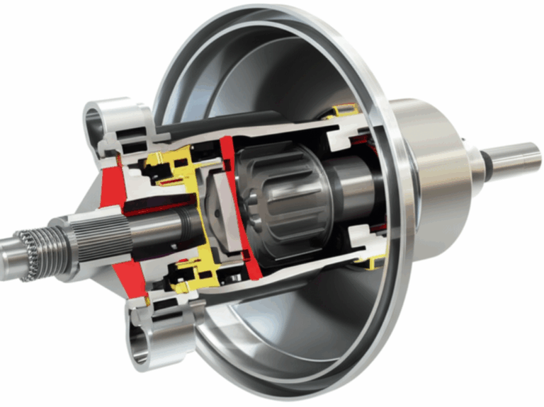
A motorcycle stator is the stationary part of a permanent magnet alternator. Magnets in the flywheel rotate around copper windings and induce an Alternating Current (AC). The regulator/rectifier converts that AC to Direct Current (DC) and clamps voltage so your motorcycle battery charges safely and your electronics stay alive. The stator and regulator/rectifier form the heart of the motorcycle charging system.
Designers choose the number of poles, slot geometry, winding gauge, and lamination stack to hit the required stator output voltage and current across engine RPM. Most modern bikes use a three phase stator for smoother output and higher power density. Some small engines use a single phase stator because it is simpler and cheaper.
Common Symptoms of a Failing Stator
You do not need to guess. Stator issues leave clear electrical breadcrumbs.
- Battery not charging motorcycle symptoms after a ride
- Dim headlights motorcycle at idle that brighten with revs or stay dim
- Weak spark motorcycle and intermittent misfires on some models
- Bike will not start after sitting even with a new battery
- Charging system indicator light on some dashboards
- Overcharging motorcycle battery or undercharging motorcycle battery
- Intermittent charging problem that worsens hot
You will also see visual clues. Melted stator connector housings. Darkened or burned stator windings. Oil that smells scorched. These point to overheating and rectifier trouble in many cases.
What’s Really Going On? The Engineering Fundamentals of Stators and Laminations
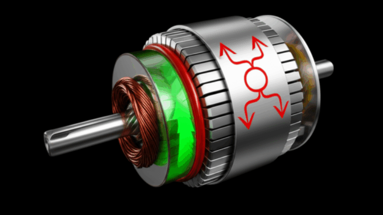
If you picture electrical losses like heat leaks in a building you will get why lamination quality matters. In a stator core the changing magnetic field drives two main loss mechanisms.
- Hysteresis loss: Energy spent flipping magnetic domains every cycle. It scales with frequency and material properties like coercivity which is the resistance to magnetization reversal.
- Eddy current loss: Circulating currents induced in the steel by changing flux. These are like little whirlpools of electricity that create heat.
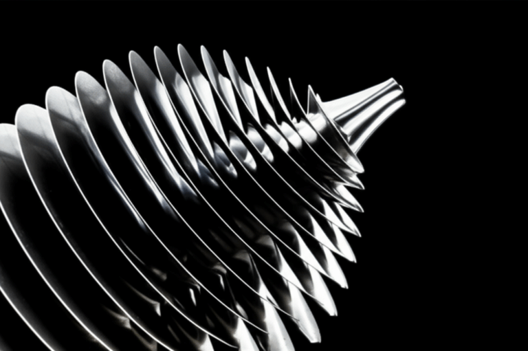
Thinner, insulated laminations break eddy current loops into tiny pieces. That is why designers stack many thin sheets rather than use a solid steel core. Material choice matters here. Non-oriented silicon steels with optimized thickness and coatings reduce both eddy current loss and hysteresis loss. That means lower stator temperatures and longer life.
- Magnetic permeability describes how easily flux passes through the core much like how a sponge soaks up water.
- The B-H curve shows the relationship between flux density (B) and magnetizing force (H). You want high permeability and low loss at your operating flux and frequency.
- Core stack factor, interlaminar insulation quality, and assembly pressure influence actual performance more than datasheets alone suggest.
For engineers and procurement teams this is the bridge between field failures and sourcing. If you see a pattern of overheated stators and burned windings in a platform you should look at:
- Electrical steel grade and thickness
- Insulation coating class and consistency
- Lamination burr and interlaminar short risk after stamping or laser cutting
- Slot fill and thermal path to oil
- Regulator/rectifier behavior at elevated temperatures
You can read more about the role of the stator’s steel stack here: the quality of the stator core lamination directly impacts efficiency, heat, and service life.
Standards and references that govern fundamentals include:
- IEC 60034 series for rotating electrical machines fundamentals and testing methods
- IEC 60404 series for magnetic materials characterization
- ASTM and ISO standards for electrical steel and coatings selection and verification
I will not drown you in acronyms. The key point is simple. Better lamination material and processing reduce heat which improves charging stability and stator longevity.
Tools You’ll Need for Stator Testing
Essential Diagnostic Equipment
- Digital Multimeter (DMM) with AC voltage range and low-ohm resolution
- Service Manual for your model to get exact stator resistance specification and AC output targets
- Battery charger or maintainer to start with a fully charged battery
- Back-probe pins or sharp multimeter test leads for clean contact
Other Helpful Tools
- Basic hand tools to access the stator connector
- Shop rags and a non-contact thermometer if you want to record hot vs cold readings
- Contact cleaner and dielectric grease for connector care
- Wiring diagram for your motorcycle charging system
- Safety gear: gloves and eye protection
Safety First: Before You Begin
Electrical work on a running engine adds risk. A few reminders to keep you safe and your readings accurate.
- Disconnect the battery before resistance and continuity tests
- Allow hot engines to cool to avoid burns on the stator cover and exhaust
- Keep hands, clothing, and leads away from moving parts when the engine runs
- Use insulated tools and stable ground reference points on the engine case or frame
- Secure the stator connector so it does not touch the frame while you test AC voltage
- Check fuses and ensure no exposed wires can short during testing
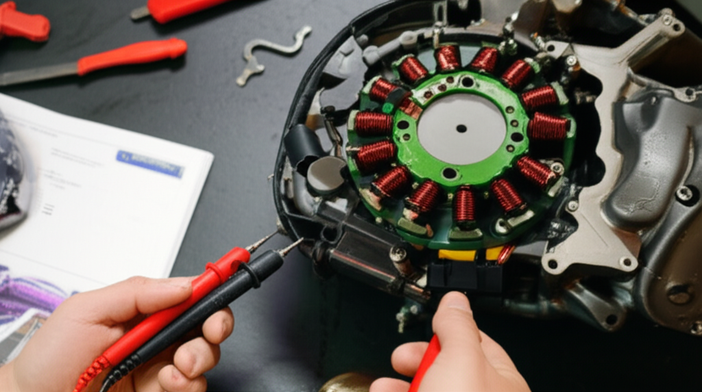
Step-by-Step Stator Testing Procedure
I will take you through the core tests. You will check battery health. Then resistance between stator windings. Then continuity to ground. Finally AC voltage output with the engine running. Follow this diagnostic flow chart motorcycle charging style sequence to avoid chasing ghosts.
Step 1: Battery Health Check (Crucial First Step)
A weak battery will trick you into blaming the stator. Start here.
- Charge the battery fully with a smart charger
- Perform a load test if possible or have a shop do it
- Check battery charge level with the DMM
- Inspect battery terminals for corrosion and tightness
DC voltage at battery terminals should show roughly 12.6 V for a healthy fully charged lead-acid battery at rest. Anything below 12.3 V hints at low charge or battery issues. Fix that first.
With the engine running you will measure charging voltage later. Keep that in mind because the regulator/rectifier can fail and cause overcharging motorcycle battery readings or low charging voltage at idle.
Step 2: Locate and Disconnect the Stator Connector
Find the stator’s three-wire (three phase stator) or two-wire (single phase stator) connector. It often runs from the stator cover to the regulator/rectifier.
- Refer to your service manual and wiring diagram
- Inspect the stator connector for heat damage, discoloration, or electrical connector corrosion
- Check the wiring harness for chafing and oil contamination
- Clean contacts and apply dielectric grease when you reassemble
Burned housings and signs of overheated stator connectors point to high current and poor contact. That is a reliability red flag for both maintenance and design.
Step 3: Perform a Resistance Test (Ohms Test)
This verifies continuity of the stator windings. You are checking for open circuits or shorts between phases.
- Multimeter Setup: Set your DMM to Ohms Ω on the lowest range that can resolve tenths of an ohm. Some meters have a “relative” or “zero” mode that subtracts lead resistance which helps with low values.
- Procedure for a three phase stator:
- Label the three stator wires A, B, C
- Measure A to B, B to C, and A to C
- Record each stator winding resistance value
- Procedure for single phase stator:
- Measure between the two stator leads
Interpretation:
- Typical values are low like 0.1–1.0 Ω although exact spec varies by model. Always check your service manual specifications.
- Infinite resistance indicates an open circuit stator winding
- A significantly high value vs spec suggests damaged windings or poor connections
- Near zero ohms across pairs suggests a short circuit between coils
Pro tip: Wiggle the harness gently during readings to catch intermittent faults.
Step 4: Perform a Ground Continuity Test
You want zero continuity between any stator lead and ground. Any reading indicates a short to ground that will kill output and can fry the regulator/rectifier.
- Multimeter Setup: Set the DMM to Ohms or continuity mode
- Procedure:
- Probe each stator lead to a good ground reference point on the engine case or frame
- Repeat for all leads
- Interpretation:
- A good stator shows infinite resistance to ground
- Any continuity means an insulation breakdown or a pinched wire path to ground
This test is your ground fault detection step. Many “mystery” charging failures boil down to this simple check.
Step 5: Perform an AC Voltage Output Test (Engine Running)
Now you will measure the raw AC output. This isolates the stator from the regulator/rectifier.
- Multimeter Setup: Set the DMM to AC voltage with an AC voltage range that covers at least 100 VAC
- Procedure:
- Start the engine then allow it to warm up
- Measure AC voltage between A-B, B-C, and A-C for three phase stators
- Record readings at idle and at 3000–5000 RPM or whatever RPM your manual states
- Interpretation:
- You should see similar readings across all pairs
- Typical ranges often land near 20–30 VAC at idle and 40–70 VAC at 3000–5000 RPM depending on the bike
- Low or inconsistent readings across phases indicate a weak or failing stator
- A phase pair that reads near zero flags an open or short in that branch
Engine RPM matters. Some bikes show no charging voltage at idle so do not panic if idle values look low. Use the spec in your manual because rotor magnet strength and winding design change the numbers.
Step 6: Optional Regulator/Rectifier Testing
You came here for stator testing. Still you should verify the downstream component when readings look off.
- DC Voltage at battery terminals with engine running:
- Expect roughly 13.5–14.7 V DC at 3000–5000 RPM depending on the bike
- Below 13.0 V suggests undercharging motorcycle battery conditions and points to a stator or R/R issue
- Above 15.0 V suggests an overcharging motorcycle battery which often means a bad regulator
- Diode test on regulator rectifier testing:
- Many DMMs have a diode test mode
- Follow your service manual because layouts vary by Yamaha, Honda, Suzuki, Kawasaki, Harley-Davidson, Triumph, Ducati, KTM, and BMW motorcycle designs
If your stator passes the AC test and the battery fails to charge then the R/R sits in the hot seat.
Step 7: Hot vs Cold Testing
Some faults only appear when hot. If you suspect a thermal issue:
- Perform the resistance, ground, and AC voltage test motorcycle stator steps when the engine is cold and again after a 10–15 minute ride
- Compare the results to catch insulation breakdown that only shows during a hot engine stator test
Interpreting Results and Common Failure Patterns
Summarize your readings and match them to failure modes. Use the table in your manual when possible. The patterns below hold across most permanent magnet alternators.
- Good Stator
- Resistance between phases matches spec and is consistent across pairs
- No continuity to ground
- AC voltage rises with RPM and remains consistent across pairs
- Open Circuit
- Infinite resistance on one phase pair
- Near zero AC output on that pair
- Often caused by broken connection or burnt coil lead
- Short Circuit Between Windings
- Near zero ohms on a phase pair
- Low AC voltage
- Overheating signs in windings
- Short to Ground
- Continuity between a stator lead and ground
- Low or erratic AC output
- Regulator failures often follow due to excess ripple and heat
- Thermal/Intermittent Failure
- Passes cold engine stator test
- Fails after heat soak during hot engine stator test
- Insulation damage or marginal solder joints likely
- R/R Related
- Stator AC voltage within spec
- DC charging voltage at the battery low or high out of range
- Replace the regulator and reinspect connectors
Common root causes:
- Stator insulation breakdown from heat and vibration
- Poor connector contact and corrosion that raise resistance and heat
- Failed regulator that cooks the stator
- High electrical loads beyond design (extra lights and heated gear) that push the charging system hard
What to Do If Your Stator Is Bad
You have a diagnosis. Now make a plan that considers cost, reliability, and the bigger picture.
Replacement vs Repair
Most shops replace the stator rather than repair it. Rewinding can work in experienced hands yet quality varies and warranty support can be limited. If you choose repair verify insulation class, varnish bake process, and test reports.
Considerations for Replacement
- OEM vs aftermarket
- OEM parts usually match form, fit, and expected stator output requirements
- Quality aftermarket options can perform well at lower cost if the supplier uses solid materials and process control
- Costs
- Most stator replacement cost ranges from $100–$500 for parts depending on brand and bike class
- The whole charging system
- Replace damaged connectors and inspect the wiring harness
- Test or replace the regulator/rectifier so a bad R/R does not cook a new stator
- Ensure proper engine oil level and clean cooling paths which help wick heat from the stator cover area
Preventing Future Stator Problems
- Keep connections clean and tight
- Avoid stacking too many accessories without upgrading the charging system
- Follow preventative maintenance motorcycle intervals for electrical inspection
- Use a battery tender when storing the bike so the charging system is not forced to recover a deeply discharged battery every ride
Material and Manufacturing Choices That Influence Stator Reliability
Here is where designers and procurement managers can move the needle. When you see repeated field failures take a hard look at lamination materials, thickness, coatings, and manufacturing quality.
Material Considerations
- Non-oriented Silicon Steels (M grades)
- The workhorse for motorcycle charging systems and general-purpose motors
- Pros: Balanced cost and performance up to medium frequencies with good magnetic permeability
- Cons: Losses rise with frequency which can raise stator temperature at high RPM
- See how suppliers specify and qualify electrical steel laminations
- CRNGO (Cold-Rolled Non-Grain-Oriented) vs CRGO (Grain-Oriented)
- Motorcycle stators rely on non-grain-oriented steels because flux rotates through multiple directions in the stator teeth and back iron
- Grain-oriented steels shine in transformers where flux prefers a single direction
- Advanced Alloys and Coatings
- Cobalt alloys and very thin gauges reduce loss at high flux densities but cost more
- High-quality inorganic insulation coatings improve interlaminar resistance without hurting stack factor
Lamination Thickness and Eddy Currents
Thinner laminations cut eddy current loss which reduces heat at high frequency components of the waveform. That can pay off in a permanent magnet alternator since output frequency scales with engine RPM and pole count. Use lamination thickness and slot design as knobs in your efficiency and temperature budget.
Manufacturing & Assembly Processes
- Stamping vs Laser Cutting
- Stamping is efficient for high volume and offers good burr control with the right tooling
- Laser cutting is ideal for prototyping and complex shapes yet can leave heat-affected zones unless managed
- Interlocking, Bonding, or Welding
- Interlocked laminations can assemble like LEGO bricks and avoid heat input
- Bonding improves rigidity and damping yet adds process steps
- Welding can reduce magnetic performance near the weld seam if not controlled
- Stack Compression and Tolerances
- Tight compressive control improves thermal conduction and reduces noise
- Poor control hurts stacking factor and increases localized losses
Quality management matters across the board. Request material certs, stacking factor data, and sample loss curves at your targeted induction and frequency. Reliable suppliers of motor core laminations publish this data and back it with process capability.
Rotor Considerations
Do not ignore the other half of the alternator. Rotor magnet grade, gap, and balance influence output and heat. A rotor that demagnetizes from heat or age can mimic a weak stator. If you need a refresher on rotor builds take a look at modern rotor core lamination approaches.
Which Application Is This For? Matching Solutions to Your Motor and Use Case
You cannot pick one answer for every motorcycle. Match design and diagnostics to the use case.
- Commuter and General-Purpose Bikes (Honda, Yamaha, Suzuki, Kawasaki)
- Three phase stator test values often sit near the 40–70 VAC range at 3–5k RPM
- Non-oriented silicon steel with conventional stamping and interlocks delivers reliable performance at moderate cost
- High-RPM Sport Bikes and Track Use
- Higher electrical frequency increases eddy current and hysteresis loss
- Thinner laminations and high-grade coatings can reduce stator temperature
- Ensure robust regulator cooling to curb overheating
- Cruisers and Touring (Harley-Davidson and similar)
- Long idle periods and accessory loads stress charging systems
- Monitor DC voltage at battery terminals during idle and cruising
- Upgrade connectors and harness sections that run hot
- Off-Road and Adventure
- Vibration and contamination test insulation and connectors
- Potted or bonded stator assemblies can improve durability
If you design BLDC alternators for e-mobility or accessory drives you will face similar trade-offs in lamination choice and insulation systems. The stator principles carry over.
Frequently Asked Questions (FAQs)
Can I test a stator without removing it
Yes. You usually test at the stator connector. Resistance checks, ground continuity, and AC voltage tests do not require removing the stator cover.
What causes a stator to fail
Heat is enemy number one. High core losses from material choice and thickness feed heat. A failed regulator can overcharge and cook windings. Oil contamination and vibration break insulation down. Poor connectors burn and introduce intermittent faults. Electrical overloads from accessories can push the alternator beyond its design envelope.
How long does a motorcycle stator last
It varies widely. Many last 30,000–80,000+ miles with good materials and a healthy regulator. Poor airflow, high load, and hot climates shorten life.
Is a bad stator dangerous
It usually will not hurt you directly yet it can leave you stranded. It can also damage the battery if the system overcharges or undercharges for long periods.
How do I use a digital multimeter for stator testing
- Use Ohms to measure coil resistance
- Use continuity or Ohms to check for a short to ground
- Use AC volts to measure stator output between phase pairs with the engine running
- Use DC volts at the battery to confirm regulator performance
Do I need exact resistance values
Follow the service manual. Many stators read in the low tenths of an ohm range so meters with lead compensation help. The key is that phase-to-phase readings match and align with the spec.
What about specific brands like Yamaha or Ducati
The procedure is the same across Honda, Yamaha, Suzuki, Kawasaki, Triumph, Ducati, KTM, BMW, and Harley-Davidson. Values differ. Always confirm the voltage and ohm spec in the service manual.
Can I perform a quick stator test
Yes. Disconnect the stator connector. Start the engine. Measure AC voltage between phase pairs at 3–5k RPM. If you see strong and balanced readings the stator likely works which points you to the regulator and wiring.
Should I check the flywheel and magnets
Inspect the flywheel for cracks and confirm the magnets look intact. A loose magnet or weakened magnet reduces output even if the stator checks out. Inspect for rotor coil testing only on wound-rotor systems though most motorcycles use permanent magnets.
Will oil type affect the stator
Oil carries heat away. The right oil and level help stabilize temperature which protects insulation. Oil additives will not fix a failing winding which is an electrical problem.
Your Step-by-Step Checklist (Problem – Explain – Guide – Empower in One Page)
- Problem
- Battery dies or lights dim and you suspect the charging system
- Explain
- The stator generates AC and the regulator/rectifier creates DC for the battery
- Laminations reduce eddy currents which controls heat
- Guide
- Battery health check
- Ohm test stator windings
- Testing stator ground fault
- AC voltage test motorcycle stator at idle and 3–5k RPM
- DC voltage at battery terminals and optional regulator diode checks
- Empower
- Compare readings to service manual specs
- Replace or repair the stator if it fails any test
- Inspect and upgrade connectors and regulator as needed
- Consider lamination material and supplier quality for design improvements and procurement
A Design and Procurement Lens on Reliability
If you specify or source stators for production runs you can use field diagnostics to drive design updates. When burn patterns concentrate near tooth tips you may be seeing high local flux density. That hints at slot geometry or material grade constraints. When failures correlate with high ambient temperatures and low road speed your regulator and cooling strategy deserve attention.
Ask suppliers for:
- Loss curves at your target induction and frequency
- Lamination thickness, grade, coating class, and stack factor
- Evidence of burr control and interlaminar insulation integrity after stamping
- Thermal validation around the stator cover with oil temperatures and expected engine RPM duty cycles
Upgrading materials and processes does not just save warranty costs. It stabilizes DC bus voltage which improves ignition and ECU robustness. It also extends battery life which customers notice.
If you need an overview of component-level options for electric machines beyond motorcycles this primer on stator core lamination and the broader universe of electrical steel laminations will help you frame discussions with your manufacturing partner.
Closing the Loop: Why Diagnostics and Laminations Belong in the Same Conversation
Testing a motorcycle stator with a multimeter might feel like a purely service-level task. It is not. Every reading you take tells a story about the lamination material, the winding design, the regulator behavior, and the build quality of connectors and harnesses.
- AC voltage balanced across phases suggests healthy windings and magnets
- Resistance within spec suggests good copper and connections
- No continuity to ground confirms insulation still does its job
- Stable DC voltage at the battery confirms the regulator and wiring harness
All of those outcomes depend on smart choices in materials and processes during design and sourcing. You can use this link between field diagnostics and engineering fundamentals to reduce failures, cut heat, and improve charging system life. When you are ready to revisit design assumptions on motor steel stacks, tolerances, and assembly techniques review current best practices in motor core laminations and how they interface with the rotating assembly through the rotor core lamination.
Your Engineering Takeaway
- Start with the battery
- A weak or sulfated battery skews every reading
- Test in this order
- Resistance between coil pairs
- Ground continuity from each lead to the engine case
- AC output at idle and at 3–5k RPM
- DC charging voltage at the battery and regulator diode checks if needed
- Interpret results against the manual
- Expect 0.1–1.0 Ω across windings and no continuity to ground
- Expect AC voltage in the 40–70 VAC range at 3–5k RPM on many three phase units
- Inspect the whole system
- Look for melted connectors, corroded terminals, and damaged wiring harness sections
- Verify regulator/rectifier performance before installing a new stator
- Design and sourcing matter
- Lamination grade, thickness, and insulation drive heat and reliability
- Stamping quality, stack compression, and bonding affect performance
- Better materials cost more yet can pay back through reduced field failures
Action step: If you are diagnosing your own bike follow the steps above and note your readings. If you are designing or sourcing stators bring those real-world failure modes into your next technical conversation. Ask for data on material grades, lamination thickness, and insulation systems. Your choices upstream set the stage for stable charging and fewer surprises on the road.
Trust signals and further reading:
- IEC 60034 series: Rotating electrical machines fundamentals and testing
- IEC 60404 series: Magnetic materials measurement methods
- ASTM specifications for non-oriented electrical steels and insulation coatings
- OEM service manuals and Haynes/Clymer guides for model-specific specs
Final note: Real-world results beat hunches every time. A digital multimeter, a service manual, and a methodical test sequence will tell you if the stator is good, if the regulator misbehaves, or if a corroded connector drags your charging system down. When in doubt measure again at temperature and record the numbers. Numbers do not lie.