How to Tell If Your Stator or Rectifier/Regulator Is Bad: My Step‑by‑Step Guide
- Table of Contents
- Introduction: Why your charging system matters
- Stator vs. Rectifier/Regulator in plain English
- Symptoms that point you in the right direction
- Safety first and the tools I actually use
- Preliminary checks that save time and money
- Testing the stator: AC output, resistance, and ground faults
- Testing the rectifier/regulator: DC output and diode tests
- How I decide between a bad stator vs. a bad R/R
- Common failure causes I see over and over
- Visual cues that scream “it failed here”
- Tips to prevent repeat failures
- Costs and when I replace vs. repair
- Special notes for motorcycles, ATVs, and outboards
- Quick FAQs I get all the time
- Final thoughts and next steps
Introduction: Why your charging system matters
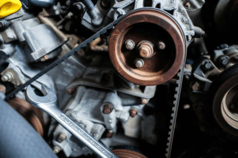
I’ve chased more “mystery no‑charge” issues than I care to admit. One time I limped home on a bike that ran fine at speed then died at idle. Another time I cooked a battery after a long highway run because the regulator decided to play volcano. In both cases the fix hinged on one question. Is the stator bad or is the rectifier/regulator (R/R) bad.
You don’t need luck to figure it out. You need a plan, a multimeter, and a few simple tests. I’ll walk you through exactly how I diagnose a charging system on motorcycles, ATVs, UTVs, and small engines with permanent magnet stators. We’ll test the battery, the stator (AC generator), and the rectifier/regulator that turns AC into stable DC. I’ll show you what numbers I expect, how to interpret weird readings, and how to spot common traps like corroded connectors or a battery that’s quietly sabotaging your test results.
By the end you’ll know how to tell if the stator or the rectifier is bad with confidence.
Stator vs. Rectifier/Regulator in plain English
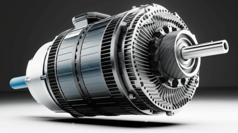
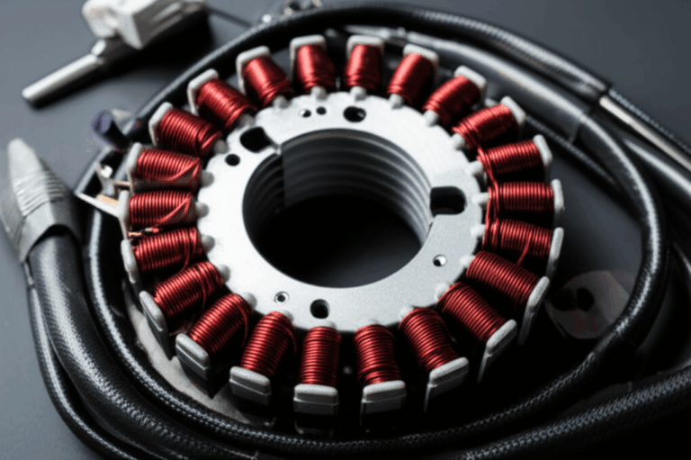
Here’s the 10‑second version. The stator is a set of copper windings wrapped around an iron core. Magnets in the flywheel or rotor sweep past the windings and that movement generates AC voltage. The rectifier converts that AC to DC. The regulator keeps that DC in a safe window for your battery and electronics.
- Stator = AC generator
- Rectifier = AC to DC conversion
- Regulator = Voltage control
Most bikes use a permanent magnet generator (PMG) with a three‑phase stator. You often see three yellow wires coming out of the engine case. Single‑phase stators exist on some small engines and older machines. The core of the stator uses stacked laminations to control magnetic losses and heat. If you’re curious about how those stacks are built the quality of the stator core lamination and the matching rotor core lamination matters for efficiency and durability. Both rely on precisely made electrical steel laminations that keep eddy currents in check.
Rectifier/regulators come in a few flavors:
- SCR shunt regulators: Common and cheap. They bleed excess energy to ground as heat.
- MOSFET shunt regulators: Run cooler and regulate faster.
- Series regulators: They reduce current flow from the stator under light loads so they usually run coolest.
If you understand that split you can test each piece logically.
Symptoms that point you in the right direction
Symptoms don’t replace testing but they can point your nose down the right trail.
Likely stator trouble:
- Battery not charging even at higher RPMs despite a known good regulator
- Dim headlights that don’t brighten with revs
- Bike runs on battery only then dies while riding
- Weak spark, engine misfires at low RPM due to low system voltage
- Burnt stator smell from the engine side cover
- Uneven AC voltage between stator phases
Likely rectifier/regulator trouble:
- Overcharging battery symptoms like swollen battery, hot acid smell, or battery acid boil over
- Undercharging at the battery even though stator AC output looks healthy
- Output voltage fluctuations while you hold RPM steady
- Repeatedly blown fuses tied to the charging circuit
- Melted or browned R/R connector and wires
- Charging system warning light that flickers or stays on
A word of caution. A failing battery can mimic both problems. So I always start there.
Safety first and the tools I actually use
You won’t need a lab. You do need a few basics.
- Digital multimeter with AC/DC voltage, resistance (Ohms), and diode check
- Service manual or wiring diagram for pinouts and specs
- Battery load tester or a shop that can perform a load test
- Small picks or brushes for connector cleaning
- Dielectric grease for reassembly
- Insulated gloves and eye protection
Work in a well‑ventilated area. Keep loose clothing away from spinning parts. Don’t short the battery terminals. If a test says “engine running” secure the bike or vehicle on a stand or level ground.
Preliminary checks that save time and money
I can’t count how many times a “bad charging system” turned out to be a loose ground or a tired battery. Do these first.
1) Battery health
- Resting voltage test: Let the battery rest for at least 30 minutes after charging or riding. A healthy 12V lead‑acid battery reads about 12.6V to 12.8V. If you see 12.2V the battery is low. If you see 12.0V it’s nearly empty.
- Cranking voltage drop: Watch battery voltage while you crank. If it drops below about 10.0V on a typical bike the battery may be weak or the starter is drawing too much. A collapsing battery can derail your charging tests.
- Load test: If in doubt load test it. Many parts stores will do a load test for free. I do this if the resting and cranking numbers look marginal.
- Visual inspection: Check for swollen battery case, acid residue, cracked posts, and corroded terminals. Clean and tighten both terminals until they’re snug.
2) Fuses and grounds
- Check the main fuse and any charging system fuses. Replace blown fuses after you find the cause.
- Inspect engine and frame ground straps. Clean to shiny metal and snug them down.
3) Wiring and connectors
- Unplug the stator connector, the R/R connector, and the battery leads. Look for melted plastic, green corrosion, burnt pins, or loose terminals.
- If a connector looks cooked replace it. High resistance at a bad connector creates heat and voltage drop.
If the battery and connections check out you’re ready for hard numbers.
Testing the stator: AC output, resistance, and ground faults
Here’s my sequence for a three‑phase stator. I’ll note differences for single‑phase as we go.
Important: Always consult your service manual for exact specs and procedures. Values vary by machine but the process stays the same.
Step 1: Disconnect the stator from the rectifier/regulator
- Find the stator’s AC output connector. It usually has three same‑color wires.
- Unplug it so you isolate the stator from the R/R.
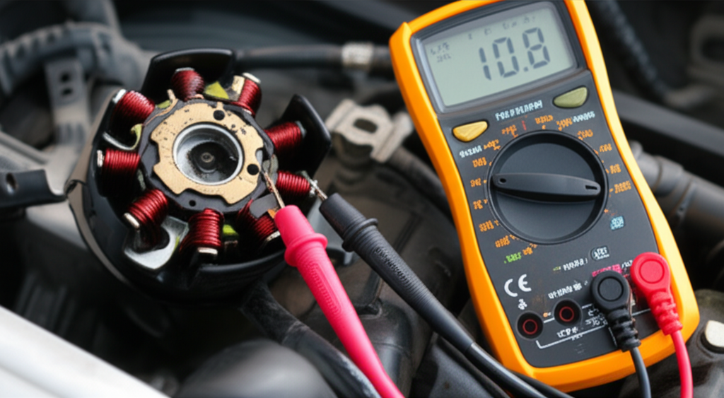
Step 2: AC voltage test with the engine running
- Set your multimeter to AC volts.
- Start the engine. Measure AC voltage between each pair of stator wires: A‑B, B‑C, and A‑C.
- Note the RPM. I test at about 2,000 RPM and again near 4,000‑5,000 RPM.
What I expect:
- All three pairs should read similar AC voltage at a given RPM. I often see 20‑30 VAC at fast idle and 40‑70+ VAC at 4,000‑5,000 RPM on many bikes. Some systems produce more.
- If one pair reads much lower than the others you likely have a partial short or open in that phase.
- If all phases read low across the board suspect a shorted stator, weak rotor magnets, or a flywheel issue.
For single‑phase stators:
- You’ll have two wires. Measure AC voltage between them. Compare to the spec in your manual.
Step 3: Stator resistance check with engine off
- Set your meter to Ohms on a low scale.
- Measure resistance between each pair of stator wires: A‑B, B‑C, and A‑C on a three‑phase unit.
What I expect:
- Low and consistent readings. Often around 0.1 to 1.0 Ohm depending on the machine and meter leads. Use the manual spec if provided.
- If one pair reads open (infinite) you have an open winding.
- If one pair reads higher or lower than the others by a large margin the winding is damaged.
Step 4: Grounding test for shorts to ground
- With the stator still unplugged measure resistance from each stator wire to engine ground or the engine case.
What I expect:
- No continuity to ground. The meter should show OL or very high resistance.
- Any continuity to ground indicates a shorted winding or damaged insulation.
If the stator passes resistance and ground tests but AC output is low I look at the rotor and the mechanical side. I’ve seen flywheel magnets that lifted and shifted which chewed up the stator. I’ve also seen damaged cores and overheated windings. Manufacturing choices for cores matter here as well since poor lamination quality can raise losses at high RPM. That is one reason quality motor core laminations and precise stacking pay off in real performance.
Optional but useful: Output balance check
- Compare AC voltage between pairs at the same RPM. If you see 60V, 60V, and 20V at 5k RPM you have a clear phase failure.
If the stator fails any of these tests you found your culprit. If it looks good move on to the R/R.
Testing the rectifier/regulator: DC output and diode tests
The rectifier/regulator does two jobs. It converts AC to DC then regulates DC to a safe range for the battery and electronics. I test both functions.
Step 1: Battery‑connected DC voltage test
Some R/Rs will not regulate properly unless the battery is connected as a buffer. So I start at the battery on most modern bikes.
- Reconnect the stator to the R/R.
- Ensure the battery is connected and in decent health.
- Set the meter to DC volts.
- Measure battery voltage at idle then at 2,000‑5,000 RPM with lights on.
What I expect:
- A stable charging voltage between about 13.5V and 14.8V at cruising RPM on a 12V system. Check your service manual for the exact spec.
Interpretation:
- Undercharging: If you see 12.5V to 13.0V or less at 3,000‑5,000 RPM the system is not keeping up. If your stator AC output was strong the R/R is likely bad. If the stator AC output was low your stator is the problem.
- Overcharging: If you see 15.0V and above at higher RPM you have a failed regulator. Park it until you fix it because overcharge cooks batteries and ECUs.
- Unstable or oscillating voltage: Fast jumps or surges usually point to a failing regulator, a weak battery, or poor connections.
Step 2: Isolate and test R/R output directly if needed
Some systems allow you to disconnect the R/R output to the battery and measure DC at the R/R plug. Many do not regulate correctly without the battery in circuit. I use this test sparingly and only when I have a known good battery in place.
Step 3: Rectifier diode check
Most multimeters have a diode test mode. You can test the rectifier bridge for opens and shorts.
- Disconnect the R/R completely so you don’t read back through the system.
- Identify the AC inputs from the stator and the DC positive and negative outputs.
- Place the meter in diode mode. You will test from each AC input to the DC positive then reverse the leads. Repeat from each AC input to the DC negative then reverse the leads.
What I expect:
- In one direction you should see a forward voltage drop often around 0.4 to 0.7V.
- In the reverse direction you should see OL or a very high reading.
- If you read low in both directions you have a shorted diode.
- If you read OL in both directions you have an open diode.
A failed diode reduces output on that phase which shows up as low or uneven charging under load. Diode pack testing is simple but effective when the R/R refuses to hold voltage under normal use.
Step 4: Heat and location check
R/Rs hate heat. If the unit sits behind a fairing with zero airflow it will cook. MOSFET and series regulators survive heat better than old SCR shunt units but everything has a limit. If the heat sink is discolored or the potting looks bubbled the unit saw high temps.
How I decide between a bad stator vs. a bad R/R
When I finish the tests the decision is usually clear. Here’s my cheat sheet.
Call it a bad stator if:
- AC voltage is low at the stator plug or uneven between phases at the same RPM
- Any phase shows continuity to ground
- Any phase shows open or wildly different resistance
- The rectifier/regulator passes diode tests yet battery charging stays low
Call it a bad rectifier/regulator if:
- Stator AC output is healthy and even across all phases
- Battery voltage is low at RPM with a good stator and clean connectors
- Battery voltage runs high above 15.0V at RPM
- Diode tests show shorted or open diodes
- Output fluctuates wildly while engine RPM is steady
Underrated culprit:
- Connectors and grounds. The best stator and a new R/R cannot charge through a burnt plug or a corroded ground. I sometimes run a quick voltage drop test across connectors. With the engine revved and the system charging measure DC voltage from the R/R positive output to the battery positive. Then measure from R/R ground to battery negative. Anything more than a few tenths of a volt suggests a bad connection.
Common failure causes I see over and over
Once you see the patterns you start to predict the failure before you even pull out the meter.
- Heat soak: R/R mounted behind a hot engine with poor airflow. Shunt regulators bleed energy as heat so location matters.
- Poor connectors: Loose spades on the stator plug. Melted plastic from high resistance. Corroded pins at the R/R output. This kills both parts.
- Overloaded electrical system: Add fog lights, heated gear, and a beefy sound system to a small stator and you’ll run it at max output all the time.
- Weak battery: A dying battery forces the R/R to work harder which raises heat. It also throws off test results.
- Oil contamination: Some wet stators bathe in oil which is normal. If the insulation breaks down you get shorts to ground.
- Rotor damage: Loose magnets, damaged flywheel, or debris that scuffs the windings. If a rotor loses magnet strength output drops across all phases.
For the geeks among us the stator and rotor use laminated cores to reduce eddy current losses. The material and stacking order affects heat and efficiency at high RPM. That’s why the quality of electrical steel laminations and precise stator core lamination stacks makes a difference in long‑term reliability.
Visual cues that scream “it failed here”
You can learn a lot from a quick look and a sniff.
Stator clues:
- Darkened or burnt windings
- Melted or brittle insulation
- Charring around a single phase
- Bits of magnet or metal stuck to the windings
- Strong burnt varnish smell from the side cover
R/R clues:
- Melted or browned connectors at the R/R plug
- Swollen or cracked potting material on the unit
- Heat sink that looks burnt
- Wires hardened from heat near the unit
Battery clues:
- Swollen case more on one side than the other
- Acid stains or a sharp sulfur smell
- Low electrolyte levels on serviceable batteries
Tips to prevent repeat failures
I hate fixing the same problem twice. These changes cut repeat failures for me.
- Improve airflow over the R/R. Relocate it if the stock spot is a heat trap.
- Upgrade to a MOSFET or series regulator when possible. They regulate cleaner and run cooler.
- Replace toasted connectors with quality sealed connectors and proper crimp tools.
- Clean and protect every high‑current connection. Use dielectric grease on clean terminals and grounds.
- Keep the battery healthy. Charge it with a smart charger if you store the vehicle for long periods.
- Avoid overloading the charging system. Balance accessory loads against the stator output spec.
- Check the flywheel/rotor if you find a failed stator. If magnets shifted fix that root cause before installing a new stator.
Costs and when I replace vs. repair
Prices swing by make and model so I won’t throw out random numbers. Here’s how I think about it.
- Stator replacement costs more in parts and labor because it lives inside the engine cover. You’ll need a puller on some models and a new gasket. I replace the stator when it fails any AC output, resistance, or ground test or when the windings are visibly cooked.
- R/R replacement is simpler and often cheaper. It bolts to the frame or subframe. I replace it when it overcharges, undercharges with a good stator, or fails diode tests.
- If connectors are melted I replace the connectors and the suspect part. Heat travels and damages both sides.
Special notes for motorcycles, ATVs, and outboards
The core tests stay the same across platforms with a few twists.
Motorcycles:
- Many bikes use three‑phase PMG stators. You’ll often see three yellow wires. Expect 40‑70+ VAC per phase at 4‑5k RPM.
- The ECU and fuel pump get cranky under low voltage so misfires or stalling at idle often trace back to charging.
ATVs and UTVs:
- Mud, water, and dust chew up connectors. I inspect the harness early in the process.
- Some models use single‑phase stators. Follow the manual for expected AC numbers.
Outboard motors and small engines:
- Magneto systems and separate charging coils show up here. The same logic applies though the connectors and specs differ.
Car alternators:
- Different animal since the rectifier and regulator usually live inside the alternator. The process shares ideas but the steps differ.
Quick FAQs I get all the time
Can I ride with a bad stator?
- Not for long. You might limp along on a full battery for a bit but the bike will die once the battery drains.
Will a bad rectifier/regulator drain my battery?
- Yes. A failed R/R can undercharge so the battery never recovers. It can also leak current when off which drains the battery overnight.
How do I know if I have a three‑phase or single‑phase stator?
- Three‑phase stators typically have three same‑colored wires exiting the engine. Single‑phase often has two. The service manual confirms it.
What’s a good charging voltage at the battery?
- I usually want 13.5V to 14.8V at 3k‑5k RPM on a 12V system. Always check your service manual.
Why do stators fail?
- Heat, vibration, insulation breakdown, and sometimes a rotor that went rogue. Overloaded electrical systems run stators hot which speeds failure.
Should I upgrade my regulator?
- If you have a known hot spot or heavy accessory load a MOSFET or series regulator can help. Placement and airflow matter just as much.
What about voltage drop tests?
- They are great for finding bad connections. With the system charging measure across a suspect connector or ground. More than a few tenths of a volt tells you that connection is weak.
Do laminations really matter?
- Yes. Stators and rotors use stacked metal laminations to cut core losses at speed. Better laminations reduce heat which helps reliability. If you want to geek out look into how electrical steel laminations and precise rotor core lamination design improve efficiency.
Final thoughts and next steps
When a charging system acts up I follow a simple flow. Verify the battery then inspect fuses and grounds. Test the stator for AC output, phase balance, resistance, and shorts to ground. Test the rectifier/regulator at the battery for stable DC voltage then confirm the rectifier diodes. Clean the connectors, fix heat issues, and retest before I call it done.
If you take anything from my experience let it be this. Don’t guess. A ten‑minute multimeter test beats throwing parts every time. Your charging system will thank you your wallet will too.
If you want to understand how core construction affects performance beyond the basics you can also read more about stator core lamination and broader motor core laminations. It’s the behind‑the‑scenes engineering that keeps your volts steady and your weekend ride out of the breakdown lane.