How to Tell if a Motor Is Locked Up—and How Lamination Design Helps You Avoid It
Every engineer runs into this problem sooner or later. A motor will not turn. The team wants to know if it is locked up, what caused it, and whether you can salvage the machine or need to replace it. You also want to stop it from happening again. If you have ever weighed field diagnostics against design choices like lamination material, lamination thickness, and assembly methods, you are in the right place.
We will start with fast, reliable checks that tell you whether the unit is actually locked. Then we will unpack why motors lock up from an engineering perspective. Finally, we will walk through material and manufacturing choices for motor core laminations that improve efficiency, reduce heat, and lower your risk of seizure in the first place.
In short, you will get a field-ready diagnostic guide and a design-ready lamination playbook in one place.
In This Article
- Quick Field Diagnosis: Is the Motor or Engine Actually Locked?
- What’s Really Going On: The Physics of Lock-Up in Electric Motors vs Engines
- Core Loss Fundamentals: Eddy Currents, Hysteresis, and Lamination Thickness
- Your Options: Materials, Stamping vs Laser, Bonding vs Welding, and Stack Construction
- Best Fit by Application: General-Purpose, High-Frequency, EV/BLDC, and Harsh Duty
- Cost, Repair vs Replace, and Procurement Tips
- Engineering Takeaways and Next Steps
Quick Field Diagnosis: Is the Motor or Engine Actually Locked?
Before you pull a motor or authorize a replacement, confirm the symptom. “Locked up” can mean a truly seized engine or motor. It can also mean a starter problem, a seized accessory, a failed bearing, a jammed drivetrain, or even an electrical control fault. The goal here is fast triage that avoids unnecessary teardown.
First look and listen: initial symptoms
- Engine won’t turn over. You turn the key or hit Start. You get silence or a single heavy click, not the rapid clicking of a weak battery. Dashboard lights come on but there is no crank. That points to engine not cranking or a locked rotating group.
- Starter motor clicking but no crank. Repetitive clicking usually points to low voltage from a weak battery or corroded terminals. That is not a locked engine by itself.
- Grinding or a harsh clunk when you try to start. That suggests mechanical interference. It can happen with broken teeth on the flywheel, a jammed starter, or internal damage.
- Visible smoke or a burning oil smell. Rare during crank attempts, yet you might see it if an accessory or bearing is seized and creating friction heat.
- Fluids out of place. Milky oil indicates coolant in oil. That can come from a failed head gasket or cracked block. You can also see water in cylinders or oil in coolant. Contamination is a cause, not proof of lock-up, yet it should raise your suspicion.
These sound like automotive symptoms because they often are. The phrase “motor locked up” is common in car and diesel contexts. The same triage logic maps to electric motors in industrial lines or EV drivetrains with a few adjustments.
Rule out the obvious: battery and starter in vehicles
- Measure battery voltage. A healthy 12 V battery should sit above about 12.4 V with the engine off. Anything around 12.2 V or lower can cause starter chatter without a locked engine.
- Watch for repetitive starter clicking. That usually means low battery voltage or a poor connection. Check grounds and terminal corrosion. Use a multimeter. Verify voltage drop during crank.
- Tap the starter motor lightly. A stuck solenoid sometimes frees up long enough to confirm the engine will turn. Do this only as a brief diagnostic step.
- Scan for ECU error codes with an OBD-II scanner. A crank sensor or camshaft position sensor issue can prevent starting. Those faults mimic a no-start but not a lock-up.
If the battery and starter check out, move to the definitive test.
The definitive test: does the crank turn by hand?
You can verify a seized internal combustion engine with a breaker bar. It is simple, quick, and conclusive.
- Safety first. Park or neutral. Parking brake engaged. Wheels chocked. Disconnect the battery.
- Locate the crankshaft pulley. It sits at the front of the engine. Fit the correct socket and a sturdy breaker bar.
- Rotate clockwise first. Try counter-clockwise if needed. A healthy engine will turn with steady effort. Compression creates pulses of resistance. A locked engine will not budge. It will feel like solid metal on metal.
What if it is still stuck? Take two quick isolation steps.
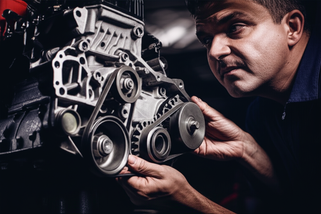
1) Remove the serpentine belt. Accessories can lock and mimic a seized engine. Spin the alternator, AC compressor, water pump, and power steering pump by hand. If the engine turns freely after removing the belt, an accessory is your culprit. Alternator locked up and AC compressor locked up show up more often than you might think. A water pump seized can also stop the belt dead.
2) Remove spark plugs. This relieves compression and exposes hydrolock. If a cylinder shoots water, coolant, or fuel when you crank by hand, you found a hydro-locked engine. Dry the cylinders. Fix the root cause like a head gasket failure or cracked head, then test again.
While you have plugs out, inspect for spark plug fouling or signs of pre-ignition and detonation. Those can precede piston damage.
Electric motor variant: quick checks without a teardown
For industrial motors or EV traction motors you cannot always swing a breaker bar on a crank. You can still isolate electrical from mechanical causes fast.
- De-energize and lock out. Safety remains step one.
- Try to turn the shaft by hand at the coupling or fan. You should feel smooth rotation. If you cannot move it, decouple the load. If the motor spins freely without the load, the driven equipment is jammed. Check the gearbox, torque converter, driveshaft, rear differential, or even a seized wheel bearing that can mimic engine issues.
- If the shaft will not turn even when decoupled, you may have bearing failure, foreign object ingestion, rotor contact with stator due to mechanical shift, or a welded spot from severe overheating.
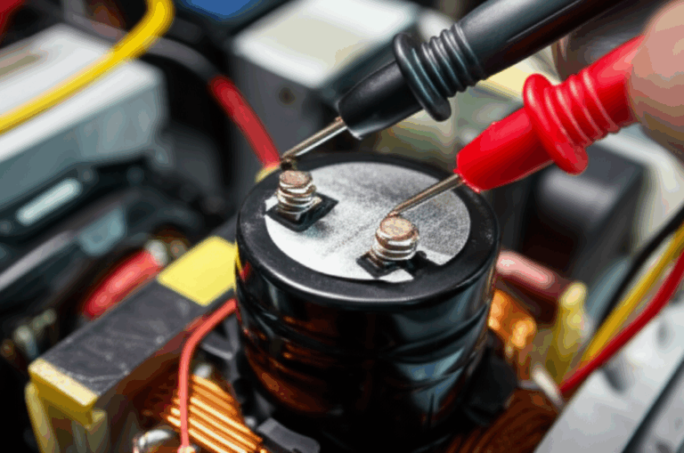
- If the shaft turns but the motor still trips breakers under power, it can be a locked rotor current scenario from control faults or a shorted turn. You diagnose with insulation resistance tests, winding resistance balance, and a look at the drive.
This field view covers “no-crank,” “engine won’t turn over,” “vehicle won’t move,” and even “transmission vs engine lock-up” questions. It keeps you out of rabbit holes.
What’s Really Going On: The Physics of Lock-Up in Electric Motors vs Engines
Lock-up is a symptom. The cause behind it ranges from simple to catastrophic. Knowing the physics helps you diagnose faster and design smarter.
Internal combustion engines: why they seize
- Hydrolock. Water, coolant, or fuel enters the combustion chamber. Liquids do not compress. The piston stops, rods bend, and bearings take a beating. You see this after floods, failed head gaskets, cracked blocks or heads, or an injector stuck open. Pull plugs to confirm. You can sometimes recover if rods did not bend.
- Lack of lubrication and oil starvation. Low oil or a failed oil pump starves bearings and cylinder walls. Metal-to-metal contact seizes main bearings and rod bearings. You often find metal shavings in oil and low oil pressure warnings before it happens.
- Severe overheating. Heat expands metal and kills the oil film. Pistons can scuff and stick. Cylinder heads can warp. You might smell burning oil or see steam. Watch the engine temperature gauge. An ignored high reading can end a motor quickly.
- Internal component failure. Throw a rod and you can crack the block. Break a timing belt or chain on an interference engine and valves hit pistons. A crankshaft or camshaft can also fail. The engine makes a clunk when starting or it stops suddenly.
- Foreign object ingestion. Debris in the intake or through a spark plug hole can lock a piston.
Add-on components create lock-like symptoms. A seized alternator, AC compressor, or water pump can stop the belt cold. That keeps the crank from turning even with a healthy bottom end.
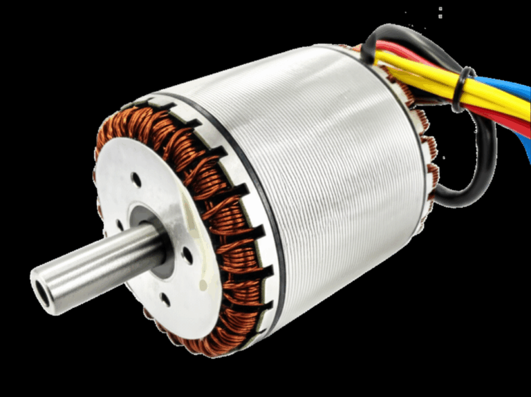
Electric motors: the lamination and thermal story
Electric machines do not “hydrolock.” They seize due to mechanical or thermal issues that often tie back to core losses and heat.
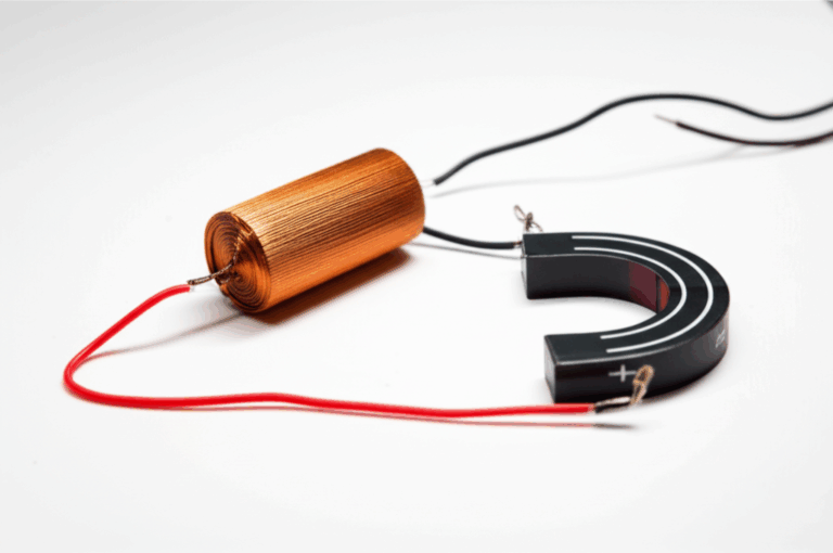
- Core losses drive heat. Hysteresis loss is the energy spent flipping magnetic domains each cycle. Eddy current loss is the heat generated by induced circulating currents. Think of eddy currents as little whirlpools in a river. Thinner, insulated laminations break those whirlpools into tiny swirls. Less heat means less risk of insulation breakdown and bearing grease cook-off.
- Bearings fail when heat rises. Overheating degrades lubrication. It can warp components. A rotor can rub a stator if clearances collapse.
- Shorted turns and localized heating can distort the rotor or stator stack. That yields rubs at speed or a hard lock at standstill.
- Accessory issues mimic lock-up on coupled systems. A jammed pump, gearbox, or seized driven machine stops everything. Decouple to confirm.
This is where lamination design does more than boost efficiency. It keeps temperatures in check, which protects insulation, bearings, and mechanical clearances. That reduces the odds that your motor locks up in the field.
Core Loss Fundamentals: Eddy Currents, Hysteresis, and Lamination Thickness
If you pick only one design lever to reduce thermal stress and avoid seizure, pick the right lamination material and thickness. It pays off immediately.
- Eddy currents. Rotating fields induce currents in the core. Those currents loop and create heat. Thinner laminations with insulation interrupt the loops. That slashes loss. It works like breaking a big puddle into small droplets so they do not pool into a flood.
- Hysteresis. This is the energy cost of cycling magnetization each AC cycle. Materials with lower coercivity reduce it. Coercivity is the material’s resistance to being demagnetized. Lower is better for loss.
- Frequency matters. As frequency rises, eddy current losses climb fast. That is why high-speed and BLDC machines benefit from very thin laminations and high-grade steels.
- Grain orientation matters. Non-oriented (NOES) electrical steel is isotropic in the plane and suits rotating machines. Grain-oriented (GO) steels excel in transformers with unidirectional flux paths.
- Surface insulation class matters. Good interlaminar insulation keeps sheets electrically isolated. That limits eddy currents at stack level. It also influences bonding options.
Standards exist for both materials and test methods. ASTM A677 and related specifications cover non-oriented silicon steel in many grades. IEC 60404 specifies methods for magnetic property measurement. IEC 60034 covers rotating electrical machines broadly. If your supplier quotes loss curves and B-H curves, ask which standards they follow.
Your Options: Materials, Stamping vs Laser, Bonding vs Welding, and Stack Construction
Let’s move from physics to your bill of materials and process plan. This is where procurement managers and product designers have the most leverage.
Material considerations: pick for frequency, performance, and cost
- Silicon steels (M grades and NOES). These are the workhorse materials for general-purpose motors. They offer a balance of cost and magnetic performance up to a few hundred hertz. Typical thicknesses run 0.50 mm, 0.35 mm, and down to 0.27 mm for higher performance. Thinner gauges cut eddy currents yet raise cost and increase stamping challenges. Learn more about available options for electrical steel laminations.
- High-silicon NOES. Better for higher-frequency applications. Lower core losses than standard grades. Watch brittleness as silicon content rises.
- Cobalt alloys. Outstanding performance at high flux densities and high temperatures. Aerospace and high power density machines use them. Cost runs high. You need to justify the performance boost.
- Amorphous and nanocrystalline alloys. These excel in very high-frequency applications with extremely low core loss. They can be difficult to process for complex rotor and stator geometries. Transformers use them more often than motors.
- CRGO vs CRNGO. Cold-rolled grain-oriented steel is ideal for transformer lamination core designs with a dominant flux path. Non-grain-oriented steel supports rotating machines due to isotropy.
If you build a BLDC or high-speed motor, consider thinner laminations and higher-grade NOES or cobalt. If you build a general-purpose induction motor, a mid-grade NOES in 0.35 mm often hits the sweet spot for cost and performance.
Manufacturing process choices: what changes with volume and geometry
- Stamping. The volume champion. High repeatability and low per-part cost once tooling is amortized. Burring and edge strain rise with thinner gauges. Tool maintenance matters. You can stamp interlocking features that let laminations connect like LEGO bricks. Interlocking reduces the need for welding, which can hurt magnetic properties.
- Laser cutting. Ideal for prototypes and low volumes. Excellent precision and flexibility for geometry changes. Heat-affected zones can change magnetic properties near the edge. You can control it with good parameters and post-processes.
- Wire EDM and waterjet. Niche options when you need precise edges without HAZ or when materials do not cut well otherwise. Lower throughput than stamping.
- Bonding vs welding. Bonding with adhesives or varnishes preserves magnetic properties and offers good stack rigidity. Welding can add mechanical robustness and aid assembly, yet it creates local heat zones that increase loss. If you weld, use small, well-spaced welds and verify losses. Mechanical interlocks are a useful middle ground for many designs.
Stack construction and assembly: the stator and rotor decisions
- Stator core lamination stack. Flatness, tooth geometry, slot insulation, and stack compression affect performance. Tooth tips and slot openings control leakage and harmonics. The quality of your stator core lamination directly sets the magnetic circuit for torque and efficiency.
- Rotor core lamination stack. In induction rotors, bar and end-ring casting quality matters. Skew angle can reduce cogging and acoustic noise. For PM rotors, magnet slot design and retention features are critical. The durability of your rotor core lamination helps keep air-gap concentricity and protects against rubs that become lock-up events.
- Complete motor cores. Fit, finish, and insulation systems tie everything together. That is why a capable supplier of motor core laminations adds value beyond raw material alone. You want consistent stacking, reliable insulation, and verified magnetic performance.
Best Fit by Application: General-Purpose, High-Frequency, EV/BLDC, and Harsh Duty
You have options. The trick is to match them to your operating frequency, duty cycle, and cost targets. Be candid about constraints. That honesty builds better machines.
General-purpose industrial motors
- Material. Mid-grade non-oriented silicon steel. 0.35 mm is a good baseline. Drop to 0.27 mm for tougher thermal budgets.
- Process. Stamping with interlocks for volume. Use bonding or light welding if needed. Track dimensional control on the bore and stator teeth.
- Why it fits. Balanced loss, manageable cost, and robust production flow.
High-frequency and high-speed machines
- Material. Thin-gauge NOES, high-silicon NOES, or cobalt alloys as power density grows. Consider amorphous alloys if frequency is very high and geometry allows it.
- Process. Precision cutting methods during prototyping. Move to fine-blanking grade tooling or hybrid processes for volume. Keep a close eye on edge quality.
- Why it fits. Core losses dominate at speed. Materials and thin laminations pay for themselves with cooler operation and longer life.
EV traction and BLDC motors
- Material. Premium NOES with tight loss specs and thin gauge. Rotor and stator must work as a system. Magnet management dominates risk in PM rotors.
- Process. Tight tolerances and consistent insulation systems. Sophisticated bonding to handle thermal cycles. Dynamic balancing to avoid rubs at speed.
- Why it fits. Efficiency and reliability win range and warranty battles. Lock-up events must be rare. They destroy customer trust and cost a fortune to fix.
Harsh duty or high-temperature environments
- Material. Elevated temperature materials or cobalt for extreme zones. Verify varnish and bonding agents for temperature rating.
- Process. Mechanical retention for magnets and robust interlocks matter. Validate bearing systems and grease selection. Confirm stack compression consistency.
- Why it fits. Heat is the enemy of insulation and bearings. The right material and assembly keep machines turning when conditions get ugly.
When laser cutting shines vs when stamping scales
- Laser cutting. Use it for prototypes, complex geometries, and short runs. You get nimble iteration and low tooling cost. For mass production of simpler shapes, stamping wins cost and throughput.
- Interlocking laminations. These snap together like bricks. They give you rigidity without local heat zones from welding. They also speed stacking. You still need bonding or varnish in many designs to hit acoustic or loss targets.
Cost, Repair vs Replace, and Procurement Tips
Your role includes dollars and downtime. Here is how to think about the economics around locked machines and how lamination choices shift the math.
If you suspect a locked-up engine or motor in the field
- Confirm first. A simple breaker bar test saves hours. So does decoupling the load on industrial systems. You might discover a seized pump or a failed wheel bearing masquerading as an engine issue. A rear differential lock-up or driveshaft issue can stop a vehicle in its tracks. You need to separate engine vs transmission vs driveline.
- If it is a vehicle engine. A seized engine usually forces a repair vs replacement decision. Rebuilds and replacements often run from a few thousand dollars into five figures. Check the vehicle value, age, and mileage. Sometimes the car becomes a total loss. Towing a car with a seized engine requires care since some transmissions need the engine to lubricate. Insurance claim for seized engine may apply after floods or covered failures. Policies vary.
- If it is an industrial motor. Repair options include bearing replacement, rewind, or full replacement. Evaluate coil insulation condition. Look for hot spots, discoloration, and odor. Inspect the air gap for rotor rub marks. Factor in lead time for new cores vs downtime loss.
Prevention beats repair
- Routine maintenance. Oil changes and coolant system checks prevent most engine seizures. In motors, scheduled lubrication and vibration monitoring catch bearing issues early. Regularly check engine fluid levels and cooling systems. Track low oil pressure warnings and high engine temperature gauge readings.
- Smart design up front. Lower core loss laminations cut steady-state temperatures. That protects insulation and bearing grease. It reduces the odds of thermal events that distort stacks or cause rotor rubs. Good airflow and thermal design help too.
- Clear supplier specs. Define maximum core loss at your operating flux density and frequency. Specify lamination thickness and insulation class. Ask for stack factor and verify with samples. Audit manufacturing processes that impact magnetic properties.
Procurement and supplier evaluation
- Validate data. Ask for standard-compliant loss curves and B-H curves. Confirm test methods match IEC 60404. Request material certs that match ASTM or equivalent.
- Review stack construction. Verify interlock quality, burr control, and flatness. Inspect edge quality for laser cut parts. Check slot insulation and varnish coverage.
- Prototype early. For new machines, run thermal tests under representative loads. Measure temperatures at windings, bearings, and core. Confirm predicted loss matches reality. Adjust lamination material and thickness if needed.
Field Diagnostics in Detail: A Step-by-Step for “Is It Locked?”
Let’s give you a compact playbook you can hand to your techs or walk through yourself. It covers the common LSI symptom set and the practical sequence to confirm a locked machine.
Vehicles and engines
1) Battery and starter rule-out
- Battery should be above 12.4 V. If it is not, charge or jump and retest.
- Look for repetitive starter clicking. That usually signals low voltage rather than lock-up.
- Try a known-good battery. Corroded terminals can drop voltage under load.
- Tap the starter to free a stuck solenoid. If the engine then cranks, it was not seized.
2) Manual rotation test
- Put the vehicle in Park or Neutral with brake set. Disconnect the battery.
- Use a breaker bar on the crankshaft pulley. Rotate clockwise.
- If it turns with rhythmic resistance, the engine is not locked. If it will not budge, it likely is.
3) Isolation tests
- Remove the serpentine belt. Try the breaker bar again. If it turns now, an accessory is seized. Check alternator, AC compressor, power steering pump, and water pump. Spin them by hand.
- Remove spark plugs. Look for fluid in cylinders. Hydrolock is confirmed if fluid shoots out. Dry the cylinders. Fix the cause. Then retest rotation.
4) Fluids and debris checks
- Inspect oil. Milky oil indicates coolant contamination. Sparkly oil indicates metal shavings from bearing or piston scuffing.
- Check coolant for oil. That suggests a head gasket or crack.
- Pull the oil pan if practical. Look for bearing material and debris.
5) Timing and valvetrain
- If the engine uses a timing belt or chain, verify timing alignment. A broken timing belt can cause valve damage in interference engines. A hard mechanical stop can result.
6) ECU and sensors
- Scan with OBD-II. Crankshaft position sensor failure or camshaft position sensor issues can cause no-start conditions. They do not cause lock-up. You still need to confirm rotation.
Electric motors and drives
1) Power down and lockout
- Safety first. Confirm zero energy.
2) Mechanical isolation
- Attempt to rotate the shaft by hand. If you cannot, decouple the load, then try again.
- If the motor turns free after decoupling, the load is the issue. Check the driven machine, gearbox, or drivetrain.
- If the motor remains stuck, suspect bearing failure, foreign object ingestion, or rotor-to-stator rub from distortion.
3) Electrical checks
- Insulation resistance tests and winding resistance balance can reveal shorted turns.
- If the motor trips on start with a hum, consider locked rotor current caused by a mechanical jam or a control fault.
- Check sensors like the motor speed or crank sensor equivalent in a drive system.
This sequence differentiates a locked unit from gears, torque converters, driveshafts, or differentials that lock instead. It also helps you separate engine seizures from transmission problems when a vehicle will not move.
Common Root Causes and How Design Lowers Risk
It helps to connect field failures to design choices.
- Hydrolock. This is a process and usage issue. Train operators to avoid deep water and address coolant leaks early. It does not relate to lamination design.
- Oil starvation and overheating. These are mostly maintenance and thermal management problems in engines. In electric motors, overheating ties directly to core losses and cooling. Thinner laminations and better materials reduce internal heat rise. That preserves bearing life and winding insulation.
- Internal component failure. Engines can suffer a thrown rod or a broken timing chain. Electric motors can suffer magnet retention failure or rotor skew issues. Good rotor stack design and magnet retention features prevent rubs and catastrophic contact.
- Accessory seizure. A locked alternator or water pump looks like a locked engine. In an electric motor system, a seized pump or gearbox does the same. Isolation steps prevent misdiagnosis.
If you build motors for vehicles or industrial lines, you can lower thermal and mechanical stress at the source with the right core design. That is the quiet win that saves you from dramatic field failures later.
Matching the Right Lamination Solution to Your Application
You know your load profile and duty cycle. Now match them to a lamination strategy that delivers the efficiency and reliability you need.
- Low to medium frequency, cost sensitive. Choose a proven NOES grade at 0.35 mm. Use stamping with clean edges and controlled burr height. Interlock the stack and varnish.
- Medium frequency with tight thermal headroom. Drop to 0.27 mm laminations. Specify lower core loss material. Bond the stack for rigidity and acoustic performance.
- High-speed BLDC or PM machines. Use thin laminations with premium NOES. Design a rotor with secure magnet retention and a robust sleeve if needed. Balance carefully. The right motor core laminations and stack quality cut risk of rotor rubs that can lock the machine.
- Large stator stacks for industrial drives. Maintain flatness and slot insulation integrity. Small deviations drive hotspots. Work with suppliers who control stack factor and tooth geometry. See options for stator core lamination quality control and design support.
- Rotors under high mechanical stress. Validate skew and bar casting quality. Avoid distortion during assembly that narrows the air gap unevenly. A well-made rotor core lamination is your front line against rubs that escalate into lock-up under load.
Costs, Consequences, and a Realistic Look at Risk
Precise statistics vary by sector and environment. Field experience points to a few trends.
- Oil and lubrication issues sit near the top of engine failures. Many shops see 30 to 40 percent of catastrophic failures tied to oil level, oil quality, or pump problems. Prevention costs pennies on the dollar.
- Overheating accounts for a sizable portion of failures that lead to seizure. Cooling systems age quietly. Radiators clog. Thermostats stick. Hoses crack. Engines that run hot for long stretches do not forgive the oversight.
- Hydrolock spikes after flood events. Regions hit by storms see a rush of hydro-locked engines. The same happens after major head gasket failures.
- Internal component failures round out the list. Timing belt failures, fatigue cracks, and long-term wear lead to catastrophic endings.
On the cost side, an engine replacement on a typical passenger vehicle can run from a few thousand dollars into the high end of five figures. For small engines like lawnmowers, replacement beats repair. In industrial settings, the cost of downtime often dwarfs the hardware. That’s why improving motor efficiency and reliability with better laminations is not a luxury. It’s insurance.
Practical Prevention Tips You Can Put in a SOP
You can prevent lock-up events with simple habits and smart design.
- Maintenance SOPs
- Regular oil changes and fluid checks stop oil starvation. Check coolant and address leaks. Train operators to watch the temperature gauge.
- Listen for early warnings. Rod bearing knock before seizure gives you a chance to act. Engine knock, smoke from exhaust, and burning oil smell mean stop and inspect.
- Inspect drive belts and accessories. Alternators and pumps fail. A quick spin test during service catches rough bearings before they seize.
- For electric motors, track vibration, temperature, and current. Bearing faults telegraph themselves. You can catch them long before failure.
- Design SOPs
- Specify lamination thickness and grade appropriate to frequency and duty. Pick low-loss grades for high-speed designs.
- Define surface insulation class and bonding method. Control stack compression and flatness.
- Validate thermal margins with test rigs that replicate real load cycles. Confirm that predicted core loss matches measured heat rise.
- Keep the air gap honest. Tolerances on bore and rotor OD matter. Misalignment leads to rubs that can become lock-up.
The Procurement Angle: How to Ask Suppliers the Right Questions
You want a supplier who delivers consistent performance, not just metal sheets.
- Can they provide magnetic property data to IEC 60404 methods. Ask for loss at your target flux density and frequency. Ask for B-H curves and coercivity data with simple explanations and units that match your models.
- Do they control edge quality and burrs for your thickness. Burrs hurt stacking factor and can increase local losses.
- What is their stack factor for your geometry and process. It affects real magnetic cross-section.
- How do they validate interlaminar insulation. Ask for coating class and dielectric breakdown strength.
- Can they support both prototypes and production. Laser cut for early sampling. Stamp for volume. Many programs need both.
- Will they collaborate on stator slot and tooth geometry. Small changes can lower core loss and improve winding fill.
Choose partners who answer clearly. Clarity beats platitudes every time.
Your Engineering Takeaway: The Short List
- Diagnose lock-up with a simple sequence. Confirm power and starter. Turn by hand. Isolate accessories by removing belts. Pull plugs to check for hydrolock. Decouple loads on electric motors. You will find the true cause fast.
- Understand the physics. Engines seize from hydrolock, oil starvation, overheating, or broken parts. Electric motors “seize” after thermal damage, bearing failure, or rotor-stator contact. Heat sits at the center of many stories.
- Attack heat at the source with better laminations. Thinner, well-insulated laminations reduce eddy currents. Low-coercivity materials cut hysteresis. Lower core loss means cooler cores, healthier bearings, and longer life.
- Match materials and processes to your application. Use NOES silicon steels for most motors. Move to premium grades or cobalt as frequency rises. Stamp for volume. Laser cut for prototypes. Bond stacks to preserve properties and rigidity.
- Quality stacks prevent rubs and lock-up. Control flatness, burrs, stack factor, and slot insulation. The right motor core laminations supplier will help you hit those marks.
Ready for a deeper technical review of your lamination options and stack design. Bring your duty cycle, target efficiency, and envelope constraints. We will help you compare materials, thicknesses, and assembly methods so you can hit performance and cost targets with confidence.
Empowered Next Steps
- Build a fast diagnostic SOP for your techs. Use the step-by-step checks in this guide. Add photos and torque specs for your fleet.
- For new designs, set lamination specs early. Define target loss at your frequency and flux density. Pick thickness with room for thermal margin.
- Ask for sample stacks and measure core loss and heat rise at speed. Validate rather than assume. Capture the data in your DFMEA.
- Partner with a lamination supplier who can support prototyping and volume with consistent quality. Review options for stator core lamination, rotor core lamination, and broader electrical steel laminations to match your program phase.
If you are comparing silicon steel grades or debating stamping vs laser for an upcoming build, let’s set up a short technical consultation. We will map your operating frequency and thermal budget to a lamination stack you can build at scale without surprise losses or unexpected lock-up risk.
Notes and references you can trust
- IEC 60034 provides key requirements and test methods for rotating electrical machines.
- IEC 60404 defines magnetic property measurement for electrical steels and related alloys.
- ASTM A677 and related specifications cover cold-rolled non-oriented electrical steel.
- For automotive diagnostics, manufacturer service manuals and SAE-referenced procedures provide torque specs and safety steps for breaker bar checks, belt removal, and compression tests.
Those standards give you shared language with suppliers and test labs. Use them to anchor your specifications, validate results, and keep your machines out of the “locked up” category for good.