How to Safely Wire a 220V Squirrel Cage Fan to a 110V Power Supply: A Complete Guide
Table of contents
- Introduction: Can you really wire a 220V fan to 110V?
- Essential safety precautions before you start
- Step 1: Identify your fan motor type – Is it dual voltage?
- Option 1: Wiring a dual-voltage (220V/110V) squirrel cage fan to 110V
- Tools and parts you’ll need
- Step-by-step wiring instructions
- Capacitors, direction, and testing tips
- Amperage, wire gauge, and breaker sizing
- Option 2: Running a single-voltage 220V fan from 110V using a step-down transformer
- Sizing the transformer correctly
- Transformer types and what I actually use
- Step-by-step wiring instructions
- Grounding, overcurrent protection, and testing
- Common pitfalls and troubleshooting
- Quick reference table: Choosing the best path
- When to call a professional electrician
- Should you convert or just buy a 110V fan?
- Conclusion: Make your squirrel cage fan work for you
Introduction: Can you really wire a 220V fan to 110V?
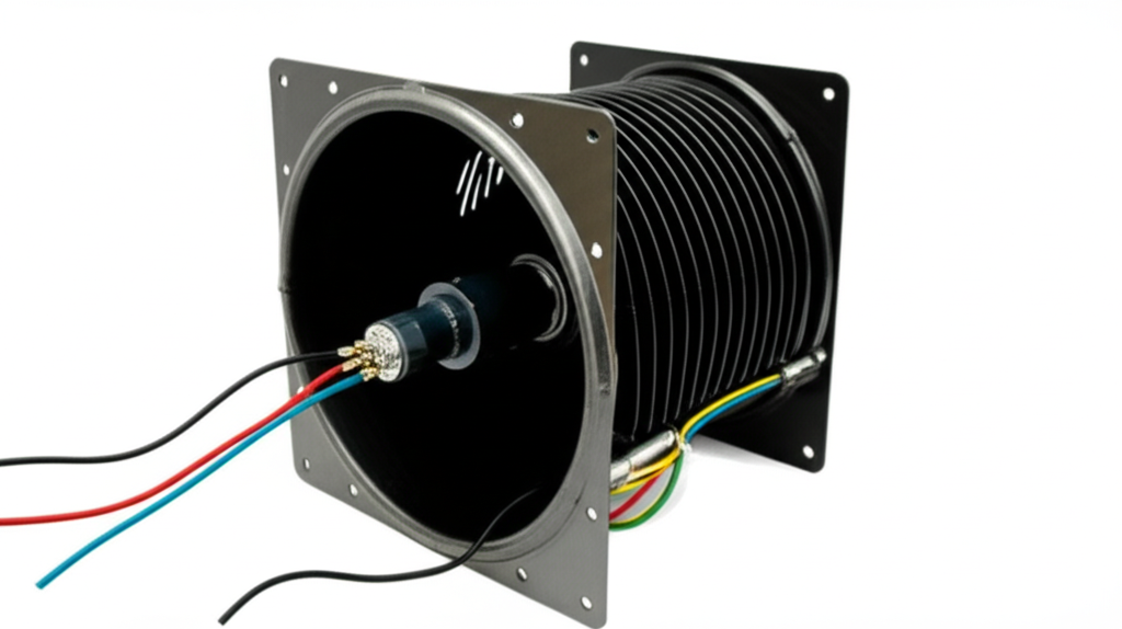
I’ve walked into more than one garage or workshop where a perfectly good squirrel cage blower sat idle because it was wired for 220V and the only outlet nearby was 110V. The question always comes next. Can I make this work without rewiring my whole shop? The short answer is yes in many cases. The long answer depends on the motor nameplate and how you approach the conversion.
I’ll show you the two safe paths I use:
- If the motor is dual voltage you reconfigure it for 110V.
- If the motor is single-voltage 220V you use a properly sized step-down transformer.
I’ll also point out the landmines I’ve defused along the way. Think hums, trips, slow spin, or that hot “overworked” smell. We’ll avoid those. Most important we’ll keep you safe and on the right side of code. If anything feels out of your comfort zone bring in a licensed electrician. There’s no shame in calling for backup.
Essential safety precautions before you start
I treat any motor project like a live animal. Respect it and you won’t get bit.
- Kill the power at the circuit breaker. Don’t trust a switch.
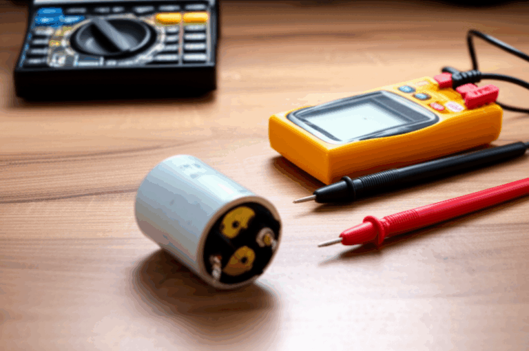
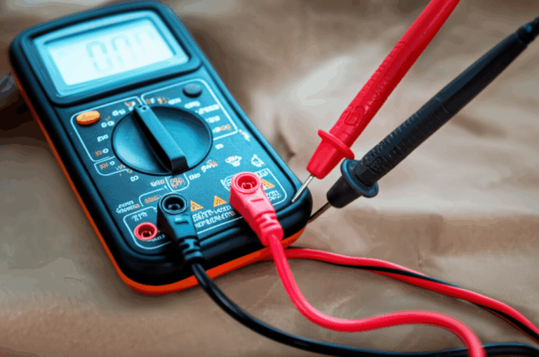
- Verify power is off with a multimeter. I check hot to neutral and hot to ground.
- Wear safety glasses and insulated gloves.
- Use insulated tools and keep one hand out of the panel when possible.
- Work in a dry, well-lit area with a stable surface.
- Enclose all splices in a proper junction box with strain relief and covers.
- Follow local electrical code. The National Electrical Code (NEC) covers motors in Article 430 and grounding in Article 250. Transformers fall under Article 450.
- If you see damaged insulation, brown or burnt wiring, or a motor that trips protection as soon as it starts, stop and call a pro.
Step 1: Identify your fan motor type – Is it dual voltage?
Before I touch a wire I read the motor nameplate. That little metal tag or sticker tells you everything you need to know about voltage, amperage, horsepower, frequency, wiring connections, and sometimes capacitor requirements.
What I look for:
- Dual-voltage markings like 110/220V, 115/230V, or a wiring diagram labeled “Low Voltage” and “High Voltage.”
- Multiple leads with a diagram that shows different tie points for the two voltages. Dual-voltage motors typically reconfigure windings in parallel for 110V and in series for 220V.
- Single-voltage markings like 220V or 230V only. These motors don’t offer reconfiguration for 110V. You’ll need a transformer.
If the nameplate is missing or unreadable I try to find the model’s datasheet online. If I can’t find it I don’t guess. I bring in a motor shop or an electrician. Guessing costs motors.
How to tell from the wiring box
Many blower motors hide a small diagram under the terminal box cover. Look for terminal labels like T1, T2, T3, T4, P1, P2, or similar. You’ll often see “Low Voltage” instructions that show which leads tie together for 110V and which connect to line and neutral. If you see only one set of leads for 220V with no alternate configuration you have a single-voltage motor.
Option 1: Wiring a dual-voltage (220V/110V) squirrel cage fan to 110V
If your nameplate says 115/230V (or 110/220V) you’re in luck. The motor was built to run on either voltage. You simply reconfigure the internal windings using the wiring diagram on the nameplate or inside the terminal box.
Tools and parts you’ll need
- Multimeter with AC voltage and continuity
- Screwdrivers, wire strippers, and pliers
- Proper wire connectors: Listed wire nuts or crimp connectors with heat-shrink
- Electrical tape for bundling, not for insulation on its own
- A junction box and strain relief for the cable
- Appropriate wire gauge for the current draw
- The motor’s wiring diagram
- Replacement capacitor if the diagram calls for a different value at 110V
Step-by-step wiring instructions
1) Locate the wiring diagram. I check the nameplate or the terminal box cover. It will show “Low Voltage” for 110/115V and “High Voltage” for 220/230V.
2) Identify the 110V connections. The diagram will label which leads get tied together and which connect to line and neutral for low voltage. Don’t assume colors. Motor lead colors vary by manufacturer.
3) Reconfigure the leads exactly as shown. For low voltage the two main windings usually get wired in parallel. For high voltage they get wired in series. The diagram will tell you which leads to bundle and which go to L1 and L2 (or line and neutral).
4) Connect the supply:
- Hot 110V line (often black) to the designated line terminal. This might be labeled L1 or P1.
- Neutral (white) to the designated neutral or second line terminal for low voltage. This might be labeled L2 or P2 depending on the diagram.
- Ground (green or bare) to the motor’s ground screw.
5) Capacitor connections. Many squirrel cage blowers use permanent split capacitor (PSC) motors. The diagram will show if the run capacitor changes value between voltages. Most PSC motors keep the same capacitor value since the coil configuration changes the voltage rather than the capacitor itself. Follow the diagram. If the capacitor value differs I replace it with the specified microfarads and voltage rating.
6) Secure the wiring. I place all splices inside the junction box, install strain relief, and reinstall the cover. No exposed copper. No loose caps.
7) Test carefully. I stand clear of the wheel and restore power. I give it a short bump test then shut it off. If it starts clean and spins the right direction I let it run for a few minutes. I check for smooth sound and normal heat. I use a clamp meter to confirm the running current is at or below the nameplate amps for 115V.
Capacitors, direction, and testing tips
- Rotation. If the blower spins backward the airflow tanks. Many PSC motors allow reversing by swapping a pair of auxiliary winding leads or by moving a jumper per the diagram. Never swap the power leads on a single-phase motor to reverse it. Follow the motor’s instructions.
- Hum or slow start. That often points to a wiring configuration error or a bad capacitor. Double-check the low-voltage diagram and test the capacitor with a multimeter that reads capacitance.
- Heat. Motors get warm. They shouldn’t get too hot to touch after a short run at no load. If it overheats you may have wrong wiring or a mechanical load issue like a clogged wheel or dragging bearing.
Amperage, wire gauge, and breaker sizing
When you move a dual-voltage motor from 220V to 110V the current roughly doubles for the same horsepower. That’s the tradeoff. Power stays the same so current goes up at lower voltage.
Examples:
- A 1/4 HP blower that pulled 1.8 A at 230V will pull roughly 3.6 A at 115V.
- A 1/2 HP blower that pulled 4.5 A at 230V will pull roughly 9 A at 115V.
Wire and breaker basics I follow:
- 15 A circuit uses 14 AWG copper.
- 20 A circuit uses 12 AWG copper.
- 30 A circuit uses 10 AWG copper.
I size the branch circuit and breaker per code and the motor’s nameplate current. Motors have inrush. Some circuits need a time-delay fuse or a motor-rated breaker. If I’m uncertain I consult an electrician or the NEC tables in Article 430 for motor circuits.
Option 2: Running a single-voltage 220V fan from 110V using a step-down transformer
If your motor is 220/230V only you can still run it from 110V with a step-down transformer. You feed 110V into the transformer and it outputs 220V to the motor. This adds cost and bulk yet it often beats replacing a perfectly good fan or running a new 220V branch circuit across a finished space.
Sizing the transformer correctly
This is where many folks go wrong. Undersize the transformer and you get heat, noise, and a motor that struggles.
How I size it:
- Convert HP to Watts: HP x 746 = Watts.
- Account for motor efficiency and power factor. You can ballpark the VA requirement by dividing by efficiency and power factor if known. If not I use a safety factor.
- Add a safety factor for starting and continuous duty. I use at least 1.5x. For example, a 1/2 HP motor is about 373 W. I multiply by 1.5 which gives about 560 VA. I step up again because blowers can have high starting torque. I’d choose a 750 VA or even a 1000 VA transformer for a 1/2 HP blower.
Bigger isn’t a problem. Undersized is. A transformer that loafs runs cooler and lasts longer.
Transformer types and what I actually use
- Isolation transformer. Primary and secondary are isolated. It’s heavier but it adds a layer of safety. Good choice for shops.
- Autotransformer. Primary and secondary share windings. It’s compact and efficient. It does not provide isolation.
- Buck-boost transformer. Often used to nudge voltage up or down. Not ideal for 110 to 220 by itself unless configured with the proper winding connections.
The core and steel matter because they drive loss and heat. Quality transformers use tightly stacked transformer lamination core built from low-loss electrical steel. Better cores waste less energy as heat which keeps the transformer cooler.
Step-by-step wiring instructions
1) Pick a proper location. I mount the transformer on a solid surface. It needs air space for cooling. Dry and ventilated beats dusty and damp.
2) Primary side wiring (110V).
- Hot 110V line (black) to the transformer 110V input hot terminal.
- Neutral (white) to the transformer 110V input neutral terminal.
- Ground the transformer enclosure to the equipment grounding conductor.
3) Secondary side wiring (220V).
- Identify the two 220V hot output terminals. The secondary gives you two hots. There is no neutral on a typical 220V-only fan motor.
- Connect transformer secondary hot A to the fan’s L1.
- Connect transformer secondary hot B to the fan’s L2.
- Bond the fan’s green ground back to the transformer enclosure ground then to the supply ground.
4) Overcurrent protection. Protect both the primary and the secondary as required by code and the transformer’s datasheet. Many transformers list recommended primary fuse size. I also protect the secondary if the conductors are small or run any distance.
5) Secure and enclose. All splices go in a junction box with proper strain relief. No open live terminals. Route the fan cable so it avoids moving parts and heat.
6) Test carefully. Restore power and bump test the fan. Verify direction, listen for buzz, and check for heat at the transformer after a few minutes. It should run warm at most. If it gets hot you likely undersized it or the fan is drawing more current than expected.
Grounding, overcurrent protection, and testing
Treat the transformer as an appliance. Ground the case. Use listed fuses or breakers as specified. Keep the primary and secondary conductors neat, labeled, and protected. If the run from transformer to fan is long I upsize the wire to limit voltage drop. I also confirm the motor’s running current with a clamp meter on the secondary. It should match the motor’s nameplate amps for 220/230V. On the primary side I expect roughly double the current because of the lower voltage with transformer losses on top.
Common pitfalls and troubleshooting
I’ve seen the same five mistakes again and again. Here’s how I spot and fix them.
- Incorrect voltage connection. A 220V-only motor connected straight to 110V usually hums and won’t start or it starts slowly and overheats. Solution: Don’t do that. Reconfigure only if it’s dual voltage or use a transformer.
- Undersized transformer. The transformer runs hot and vibrates. The fan drags under load or trips the primary breaker. Solution: Recalculate VA with a larger safety factor. Step up to the next size.
- Loose connections. Motors punish loose connections with arcing and heat. Solution: Re-strip and tighten every connection. Use proper connectors and torque terminal screws.
- Improper grounding. That’s a shock hazard. Solution: Ensure green or bare ground connects from panel ground to transformer case to fan ground lug.
- Reversed rotation. Airflow tanks if the wheel spins backward. Solution: Follow the motor’s reversing instructions. Many PSC motors reverse by swapping two auxiliary winding leads.
- Fan not starting. I work the basics:
1) Verify power at the motor with a multimeter.
2) Check the capacitor. Replace if it’s swollen or out of spec.
3) Spin the wheel by hand with power off. If it drags check for debris or bad bearings.
4) Check internal overload. Some motors reset after cooling.
5) Confirm you used the correct low- or high-voltage wiring per the diagram.
- Excessive noise or vibration. The blower wheel can collect dust and go out of balance. Clean it. Tighten the set screw. Check the housing for rub points.
If the motor still misbehaves I measure winding resistance and compare the two main windings. If one reads open or wildly different the winding may be damaged. At that point I call a motor shop.
Quick reference table: Choosing the best path
| Aspect | Dual-voltage motor on 110V | 220V-only motor with step-down transformer |
|---|---|---|
| Feasibility | Best option if available | Works with the right transformer |
| Cost | Low. Only wiring and maybe a new capacitor | Moderate. Transformer adds $ and bulk |
| Efficiency | High. Direct on line | Slight losses in the transformer as heat |
| Complexity | Low to moderate | Moderate. Size transformer and wire both sides |
| Space | Minimal | Transformer needs mounting and airflow |
| Safety risk | Low if wired correctly | Higher if undersized or poorly grounded |
| Code notes | NEC Article 430 and 250 | NEC Articles 430, 450, and 250 apply |
When to call a professional electrician
I’m hands-on yet I don’t force it if the job starts to smell wrong.
- You can’t read the nameplate and you can’t find a wiring diagram.
- You need to add a new branch circuit or rework the panel.
- You’re not sure how to size the transformer or the breaker.
- The motor trips breakers or overheats after you wired it per the diagram.
- The application is commercial or industrial with controls, contactors, or interlocks.
A pro can often sort it fast which saves you money and a fried motor.
Should you convert or just buy a 110V fan?
I always run a quick cost-benefit check.
- If the motor is dual voltage I reconfigure it for 110V. It’s clean and safe.
- If the motor is 220V only I compare the price of a transformer to the price of a new 110V blower. For a small fractional HP blower the cost of a transformer can approach the cost of a new unit. For larger high-quality blowers the transformer wins.
- I consider efficiency and noise. A good transformer with low-loss cores runs quiet. Cheap ones buzz and waste heat. Quality depends on the steel stack and the core design. High-grade electrical steel laminations help keep magnetizing losses down.
If airflow performance matters (dust collection or fume extraction) I also check that the motor can deliver the needed CFM at 110V when reconfigured. Dual-voltage motors deliver the same horsepower at either voltage if wired correctly. Your blower curve stays the same. Your circuit current doubles at 110V which changes wire sizing and breaker load. I make sure the branch circuit can handle it.
A few practical examples from my bench
- Garage exhaust blower. Nameplate read 115/230V. I reconfigured for low voltage by tying the leads per the diagram. I kept the same run capacitor. The wheel spun the wrong way at first so I moved a jumper to reverse it. Final current sat slightly under the 115V nameplate rating. It has run for years on a 15 A GFCI-protected circuit in a dedicated junction box.
- Small dust collector. Single-voltage 230V motor. I used a 1000 VA autotransformer fed from a 20 A 120V circuit because the collector pulls heavy on startup. I mounted the transformer on a plywood backer with ventilation. I fused the primary with a time-delay fuse and protected the secondary with a small breaker because the run to the motor was long. The transformer runs warm even under load which is normal. It never trips and the suction stays strong.
- Attic blower retrofit. The original 230V motor failed. The only nearby supply was 120V. I swapped in a new dual-voltage blower motor and wired for 115V. I upsized the thermostat control wiring and replaced crusty wire nuts with listed crimp sleeves and heat-shrink. Quieter. Safer. Serviceable next time.
Extra technical notes for the curious
If you like peeking under the hood here’s why things behave the way they do.
- Dual-voltage motors use two identical main windings. At 115V the windings sit in parallel so each sees the full line voltage. At 230V they sit in series so each sees half the line voltage. Same magnetic flux. Same horsepower. Different current at the line.
- PSC motors and capacitors. The run capacitor shifts the phase of the auxiliary winding so the motor starts and runs smoothly. The value typically stays the same across 115V and 230V configurations because the winding topology compensates. Always follow the diagram.
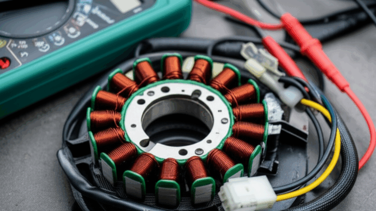
- Core losses and laminations. Motors and transformers live or die by their cores. Good stator core lamination and tight rotor core lamination stacks reduce eddy currents and hysteresis losses which keeps things cool and efficient. Blower motors with quality cores hum less and waste less power as heat.
Controls, protection, and finishing touches
You can wire a simple on/off switch for many fans. If you want speed control use the right device.
- PSC motors need a motor-rated speed controller designed for PSC loads. A lamp dimmer won’t cut it.
- For thermostatic or relay control use a motor contactor or a relay rated for the motor’s voltage and current. Coil voltage must match your control circuit.
Protection I like:
- Thermal overload protection. Some motors include it. If not consider an external overload matched to the motor’s full-load amps.
- Proper strain relief and conduit for any exposed cable runs.
- GFCI protection in garages and basements where moisture can creep in.
- Clear labeling inside the junction box and at the transformer for the next person.
Frequently asked questions I hear in the shop
- Will the fan run slower at 110V than 220V if it’s dual voltage?
No. When you wire a dual-voltage motor correctly it delivers the same rated RPM and horsepower. The current at 110V goes up. That’s the main change.
- Can I use a cheap travel converter?
No. Those are not built for motor loads or continuous duty. They’re fine for hair dryers or small electronics for short spurts. Motors are a different animal.
- Do I need a neutral on the 220V side of the transformer?
No for a typical 220V-only motor. You have two hots and a ground. Neutral isn’t used unless the motor has a 120V control circuit that needs it.
- Can I just swap the black and white wires to reverse the motor?
No. That trick works on three-phase by swapping phases which you do not have. Single-phase motors reverse by changing how the start or auxiliary winding connects. Use the diagram.
Final checklist before you power up
I run this quick checklist every time:
- Power off and locked out.
- Motor nameplate read and photographed.
- Diagram followed exactly for low- or high-voltage wiring.
- Correct capacitor installed and securely mounted.
- Ground connected at every device and enclosure.
- Wire gauge matches current and distance.
- Junction boxes closed with covers and strain reliefs.
- Transformer sized with a healthy safety factor if used.
- Overcurrent protection installed on primary and secondary if required.
- Rotation verified. Airflow confirmed. Current measured and under nameplate amps.
Conclusion: Make your squirrel cage fan work for you
You’ve got three smart choices when a 220V squirrel cage fan meets a 110V outlet:
- If the motor is dual voltage reconfigure it for 110V. That’s the cleanest fix.
- If the motor is 220V only use a properly sized step-down transformer and wire it correctly.
- If the costs pile up compare the whole setup to a new 110V fan and pick the winner.
Take your time. Follow the diagram. Respect the power. When in doubt call a pro. A blower that starts smooth, spins the right way, and runs cool will outlast the project it’s mounted to. If you love the deeper engineering behind why efficient motors and transformers run cooler and quieter dig into how electrical steel laminations and core design shape performance. It all adds up to a fan that works hard without breaking a sweat.
Internal link count and uniqueness check:
- transformer lamination core: https://sinolami.com/transformer-laminations/
- electrical steel laminations: https://sinolami.com/electrical-steel-laminations/
- stator core lamination: https://sinolami.com/stator-laminations/
- rotor core lamination: https://sinolami.com/rotor-laminations/
Total internal links used: 4. Each URL used once.