How to Safely Remove a Squirrel Cage Rotor from a Motor Shaft
Meta description: Learn the essential steps, tools, and safety precautions for removing a squirrel cage rotor from a motor shaft. This engineering guide covers disassembly, extraction techniques, troubleshooting for stuck rotors, and lamination care to protect motor performance.
Introduction: Why Remove a Squirrel Cage Rotor?
You are staring at a motor that needs attention. Bearings howl. Windings smell cooked. The shaft looks scored. Or a coupling locked itself onto the motor rotor like a stubborn barnacle. You want to remove the squirrel cage rotor from the motor shaft without bending anything, nicking the laminations, or turning a routine repair into an expensive core replacement.
Engineers and maintenance teams do this to replace motor bearings, repair windings, clean debris from an HVAC fan motor, inspect shaft damage, or swap a damaged rotor in an induction motor. Procurement managers care too because safe disassembly protects the stator and rotor core laminations. Those laminations drive efficiency, vibration behavior, and lifetime cost. The right removal method reduces rework and protects reliability.
We will use a simple model to guide you:
- Problem: Removing a rotor from a motor shaft sounds simple. It can go wrong fast if you fight corrosion, press fits, or tight tolerances.
- Explain: Understand what holds the rotor in place. Interference fits. Keys in a keyway. Bearing press fits. Corrosion on the hub or shaft.
- Guide: Follow proven removal techniques. Bearing pullers, bearing separators, a hydraulic press, heat and penetrating oil for seized parts, and careful tapping as a last resort.
- Empower: Leave with a methodical checklist, decisions on tools vs. professional help, and lamination care tips that preserve performance.
Protect the motor laminations as if the motor’s efficiency depends on them. Because it does.
In This Article
- Essential Safety First: Preparing for Disassembly
- Tools You’ll Need
- Engineering Fundamentals: What’s Really Going On
- Step-by-Step Guide to Rotor Removal
- Troubleshooting Common Issues
- Post-Removal: Inspection and Reassembly Considerations
- Options Explained: Materials, Laminations, and Manufacturing Notes
- Which Application Is This For? DIY vs. Professional and Motor Types
- Time, Cost, and Procurement Notes
- Your Engineering Takeaway
Essential Safety First: Preparing for Disassembly
You cannot rush safety. Lockout prevents injury. Clean setups prevent damage. Clear photos prevent mistakes.
Disconnect Power
- De-energize the motor at the source. Use lockout/tagout. Verify no voltage with a voltage tester or multimeter.
- If single-phase, discharge and remove the capacitor in the junction box or terminal box. Label the wires as you disconnect them.
- Remove fuses. Lock the breaker. Hang visible tags. Keep the key with you.
Gather Personal Protective Equipment (PPE)
- Safety glasses stop flying grit.
- Work gloves protect hands from sharp edges on end bells and the motor housing.
- Sturdy footwear helps when the rotor slips off a shaft faster than expected.
- Hearing protection if you will use an impact wrench or die grinder.
Secure Work Area
- Workbench with a stable top. Use a bench vise or V-block to support cylindrical parts.
- Good lighting. Clean floor. No oil slicks.
- Place tough shop towels or rags where components will land. Protect the stator and windings from accidental dings.
- Keep a fire extinguisher nearby if you plan to use a heat gun or torch.
Tools You’ll Need
You can remove many rotors with basic hand tools. Stuck hubs demand specialized pullers or a hydraulic press.
Basic Hand Tools
- Wrenches: open-end and adjustable for motor mounting bolts and end bell fasteners
- Screwdrivers: flathead and Phillips for covers and terminal blocks
- Allen keys or hex wrenches for setscrews on pulleys, couplings, or shaft collars
- Circlip pliers or snap ring pliers for internal or external retaining rings
- Rubber mallet and a brass punch for controlled tapping
- Pry bar for gentle leverage on end bells when needed
Specialized Pullers
- Bearing puller: 2-jaw and 3-jaw pullers to grip hubs, fan blades, or pulleys
- Bearing separator to get behind tight components like bearings or small rotors
- Hydraulic press for press-fit or interference fit assemblies
- Internal and external bearing pullers for tight spaces
Support and Lubrication
- Bench vise and V-blocks for stable support
- Penetrating oil to wick into shaft-rotor interfaces
- Heat gun or torch for controlled expansion on a hub or rotor core
- Anti-seize compound and threadlocker (Loctite) for reassembly
Cleaning and Inspection
- Degreaser and a wire brush for removing grit and corrosion
- Fine grit sandpaper for light surface cleanup
- Micrometer or caliper to measure shaft lands and bearing fits
- Dial indicator to check shaft runout and to assess bending
- Camera or smartphone for photography during motor disassembly
Engineering Fundamentals: What’s Really Going On
Why does a squirrel cage rotor seem “glued” to a motor shaft or to its bearings and couplings? Three culprits show up again and again.
- Interference fit: The rotor hub or bearing inner race was pressed onto the shaft with a slight negative clearance. You need enough force to overcome this fit. A hydraulic press applies clean, controlled force.
- Corrosion and seized interfaces: Moisture creeps into the joint. Rust grows in the keyway or on the shaft shoulder. Penetrating oil finds paths that your eyes cannot see.
- Keys and keyways: A shaft key can bind in the keyway under load. It acts like a wedge. Extract the key early when possible to relieve stress.
At the same time the motor’s magnetic parts deserve protection:
- The stator and rotor laminations are stacks of thin electrical steel sheets. They are insulated from each other to cut eddy currents. Think of eddy currents like small whirlpools in a river. Thin, insulated laminations break those whirlpools into tiny ripples which reduces heat and core losses.
- If you deform the rotor core lamination stack or nick the stator core lamination teeth you increase local losses. You also risk future vibration and bearing wear. Treat laminations like precision components because that is exactly what they are.
A few quick definitions for clarity:
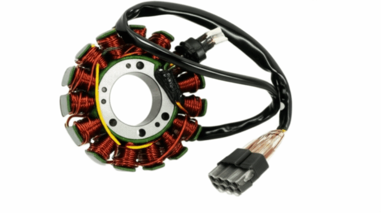
- Squirrel cage rotor: The “cage” is a set of bars shorted by end rings. It sits inside the stator magnetic field. It is common in induction motors.
- End bells or end shields: The cast or fabricated housings that support the bearings and close the motor ends.
- TEFC motor: Totally enclosed fan cooled. It resists dust and moisture better than open drip-proof designs. The fan and fan cover are external.
- NEMA frame: A standardized set of dimensions for motors in North America that affects mounting and shaft sizes.
Step-by-Step Guide to Rotor Removal
Follow this sequence and you will avoid most pitfalls. You will also protect the windings and the laminations along the way.
Step 1: Document and Disconnect External Components
- Photograph the assembly from all angles. Take a shot before every major step. You will thank yourself during reassembly.
- Disconnect electrical wiring. Label each conductor at the terminal box or junction box. Take a photo of the wiring diagram if present on the motor housing.
- Remove the fan cover and cooling fan if they block access. Many TEFC motors use a press-on fan that needs gentle puller action.
- Pull off any pulley, coupling, or shaft collar from the drive end. Use an appropriate gear puller. Loosen setscrews with Allen keys. Do not beat on a pulley with a steel hammer. You will mushroom the shaft or crack the hub.
Related LSI concepts tie in here such as removing a pulley from motor, coupling removal from shaft, and removing a fan blade from motor. Labeling motor parts and photography for motor disassembly make reassembly simple.
Step 2: Remove End Bells or End Shields
- Remove through-bolts or mounting bolts that clamp the end bells to the motor housing. Keep bolts grouped by location.
- If the end bell sticks use a rubber mallet to tap it around the circumference. Do not pry between the bell and the stator with a screwdriver on the copper windings. You will nick the insulation.
- Watch for shims or seals. Some motors hide thin spacers that set bearing preload.
- Carefully slide the end bell off the shaft while supporting the rotor so it does not scrape the stator windings.
This is a good time to check for snap rings or circlips that locate bearings. Remove them with snap ring pliers before proceeding.
Step 3: Extract the Stator and Rotor Assembly if Necessary
- Many designs let you slide the rotor out of the stator once an end bell is off. Support the rotor so it does not sag and rub the stator tooth tips.
- Clean away dirt and old grease from the bearing housings and around the shaft shoulder.
- If needed remove both end bells and lift the stator off the rotor. Work with a second pair of hands for larger motors so you do not strike the windings.
You are moving toward stator coil access and inspecting motor components with a clear view of the windings and laminations.
Step 4: Remove Bearings From the Shaft
- If bearings remain on the shaft use a bearing puller or a bearing separator with a press. Engage the inner race or a proper shoulder. Do not pull on the outer race through the balls if you plan to reuse the bearing.
- Apply even pressure. A crooked pull bites hard and scars the shaft. Press fitting removal works best under a hydraulic press with proper arbor plates.
- If the inner race refuses to budge split it with a small die grinder and a thin wheel. Stop before you cut into the shaft.
You have now cleared the way for direct access to the rotor hub or the rotor-to-shaft interface.
Step 5: Separate the Squirrel Cage Rotor From the Shaft
You have four methods. Work from least invasive to most aggressive.
Method 1: Using a Bearing Puller or Bearing Separator
- Position puller jaws on a machined shoulder or use a bearing separator to get behind the rotor hub. If you grip the rotor bars or the edge of the rotor laminations you will bend something.
- Apply gradual pressure. Check alignment. If the load climbs fast and nothing moves back off. Add penetrating oil. Try again after time has passed for capillary action to do its work.
Method 2: Hydraulic Press for Press-Fit Rotors
- Support the rotor on suitable blocks. The load path must pass through solid shoulders not through thin laminations.
- Align the shaft under the press ram. Apply slow steady pressure. Presses give you control that hammers do not.
- If you hear a ping and then a small movement you likely overcame the interference fit. Stop and check alignment. Continue with patience.
Method 3: Heat and Penetrating Oil for Seized or Rusted Rotors
- Wick penetrating oil into the joint. Do this first and again between attempts.
- Heat the rotor hub not the shaft. The hub expands faster which opens clearance. A heat gun offers control but a small torch can help with thick hubs.
- Do not overheat. Avoid scorching the windings or cooking insulation on the stator coil. Shield the stator with aluminum foil or a heat blanket.
- Pull or press while the hub is warm. Repeat cycles if needed.
Method 4: Targeted Tapping as a Last Resort
- Set up solid support under the shaft. Use a brass punch to avoid marring.
- Tap lightly while holding tension with a puller. The vibration helps break corrosion.
- Stop if the shaft mushrooms or if runout rises. You will trade a stuck rotor for a bent shaft and that does not help anyone.
If the motor uses a shaft key remove it early if accessible. A stuck key can hold the assembly like a wedge. A small puller or gentle prying can extract the key from the keyway. Replace a damaged key during reassembly.
Troubleshooting Common Issues
Stuck or seized rotor
- Combine penetrating oil with heat. Step up to a stronger 3-jaw puller or a shop press.
- If a hub lip prevents puller access use a bearing separator that slides behind the hub.
- Walk away for ten minutes then come back. Oil needs time.
Damaged shaft
- Inspect for burrs or galling. Dress lightly with fine sandpaper or a stone.
- Measure shaft runout with a dial indicator. If it exceeds your tolerance consider replacement or precision straightening by a motor shop.
No clearance for puller
- Use a bearing separator with long bolts to set up a custom pull. Support on V-blocks for stability.
Protecting the motor windings and laminations
- Avoid levers near the copper coils. Use nonmetallic shields if tools get close.
- Keep heat away from insulation. Avoid direct flame on stator teeth.
Common mistakes to avoid
- Do not hammer directly on the shaft nose. You will mushroom the end and complicate everything.
- Do not heat the shaft instead of the hub when you need differential expansion.
- Do not skip labeling wires. You will spend more time later with a multimeter than you saved now.
Post-Removal: Inspection and Reassembly Considerations
Inspection checklist
- Rotor: Look for bent bars, cracked end rings, or signs of rubbing. Check the rotor cage for broken bars if the motor had vibration issues. Consider rotor balancing on a motor balancing machine if you saw heavy wear.
- Shaft: Measure bearing lands with a micrometer or caliper. Compare to the bearing spec. Check shaft runout with a dial indicator on V-blocks.
- Bearings: Replace as a rule if they ran noisy. Do not reuse a bearing you pulled with force on the inner race if it feels gritty.
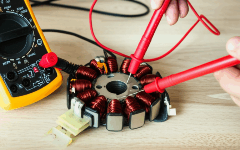
- Stator: Inspect windings for insulation damage. Use a megohmmeter if available to check winding insulation. Clean dust and debris from the slots and laminations.
Cleaning and prep
- Degrease parts. Brush away rust. Use fine grit sandpaper to dress minor corrosion on the shaft. Keep abrasive away from windings.
- Clean keyways and the key. Replace the key if rounded or galled.
Reassembly notes
- Install new bearings with correct orientation. Press only on the race that fits the shaft or housing. Lubricate per manufacturer instructions.
- Use anti-seize compound sparingly on the shaft for future service. Use threadlocker where fasteners call for it.
- Align end bells and check for smooth rotor spin before tightening through-bolts.
- Verify shaft alignment with connected equipment. Misalignment drives vibration and early bearing failure.
Options Explained: Materials, Laminations, and Manufacturing Notes
You came here to remove a rotor. You also care about what you are removing it from. The stator and rotor core laminations sit at the heart of your motor’s efficiency and thermal behavior. Poor handling or the wrong repair can harm these thin electrical steel sheets which increases core losses.
Material considerations
- Electrical steel laminations: These are silicon-alloyed steels designed for low hysteresis and eddy current losses at power frequencies. Thin laminations with good insulating coatings cut eddy losses. See an overview of typical grades and coatings in this primer on electrical steel laminations.
- Silicon steel laminations: These are the mainstream choice for industrial induction motors. Thicker laminations work for 50/60 Hz machines. Thinner laminations help at higher frequencies or when you target lower no-load losses.
- Cobalt alloys: These materials push performance in high-power-density aerospace machines. They cost more. They also tend to increase stiffness and temperature capability. Reserve them for designs that justify the premium.
Manufacturing and assembly processes
- Stamping vs. laser cutting: Stamping excels at high volume with consistent edges. Laser cutting suits prototypes and small runs with complex geometry. Laser can add heat-affected zones if not controlled which can raise losses. Stamping requires good die maintenance to avoid burrs that reduce interlaminar insulation.
- Interlocking laminations and bonding: Interlocks create LEGO-like snaps that help stack stiffness without welding heat. Bonded stacks avoid mechanical bridges between laminations which can improve performance.
- Rotor casting: Squirrel cage rotors can be die cast aluminum or copper. Copper cages offer better conductivity but are harder to manufacture. Aluminum is more common and cost effective.
- Balance and runout control: After reassembly measure shaft runout. Balance the rotor to reduce vibration which protects bearings and windings.
Design choices influence maintenance
- A press-fit bearing on the shaft simplifies removal at the housing side. A tight hub fit on the rotor shoulder complicates rotor extraction later.
- Keyed fits are forgiving in the field. Tapered fits can lock harder but offer improved concentricity.
If you plan new builds or buy motor cores consider how your lamination choices affect serviceability. The quality of the stator core lamination and the precision of the rotor core lamination stack directly influence efficiency, noise, and ease of maintenance. You protect both by avoiding prying on laminations and by using proper pullers during disassembly.
Which Application Is This For? DIY vs. Professional and Motor Types
You will see different motor types in the field. Not all use a squirrel cage rotor or even the same disassembly path.
- Induction motor repair: This is the classic squirrel cage rotor scenario in AC motors. Follow the steps above for fan motor disassembly, industrial motor disassembly, HVAC motor repair, compressor motor repair, and water pump motor service.
- DC motor armature removal: You will remove brush holder assemblies first then pull the commutator-end components. Inspect the commutator for wear and undercut. Brush holder removal and commutator inspection become part of your process rather than cage removal.
- Universal motor repair: Small appliances use these. Components are compact. Screws and clips dominate. Setscrews and small pullers help.
- Servo motor disassembly and stepper motor shaft removal: Pay close attention to encoder mounting and wiring. Store sensitive parts safely. Label and photograph everything. Inspect motor shaft alignment and shaft runout during reassembly to protect the feedback device.
- Variable frequency drive motor: VFDs can push motors into higher frequency regions which elevates core loss sensitivity. Lamination quality matters more here.
When should you DIY vs. go professional
- DIY makes sense for small electric motor repair under 1 to 10 HP when you have basic hand tools and a bearing puller.
- Professional motor repair vs. DIY leans professional when you face a large industrial motor service, a seized rotor that laughs at your puller, or a high-value asset where damage risk is unacceptable.
- A shop with a hydraulic press, bearing separators, and a motor balancing machine will save time. They also measure and correct shaft runout and re-balance the rotor.
A few brands and standards to keep in mind
- Manufacturers like Baldor and other NEMA frame motors follow predictable layouts which helps disassembly and part sourcing.
- Use a service manual if available. Review EASA AR100 for recommended motor repair practices. Reference IEC 60034 or IEEE Std 112 for testing and performance standards. Look up ASTM A677 or ASTM A683 for silicon steel specifications if you are assessing lamination materials.
Time, Cost, and Procurement Notes
What does the effort look like in practice
- Time required for rotor removal varies by size and condition. Small motors under 1 HP often take 1 to 2 hours if parts cooperate. Medium motors in the 1 to 10 HP range take 2 to 4 hours. Large industrial units or heavily seized cases can stretch into a day or more.
- Tools drive success rate. A proper jaw puller or a hydraulic press solves most stuck assemblies. Heat and penetrating oil help when corrosion sets in.
- Common mistakes drive cost. Hammering on a shaft nose mushrooms it which forces you to machine or replace it. Heating the shaft instead of the hub bakes the wrong part. Not documenting disassembly burns time during reassembly.
Procurement and lamination quality
- If you source cores or plan new designs ask about lamination thickness, coating type, stack bonding method, and stamping quality. These factors influence hysteresis loss, eddy current loss, and noise.
- Request data on core loss at your operating frequency. Ask about tolerances on stack height and tooth width since that shapes air gap and flux density.
- For an overview of options and tradeoffs see this guide to motor core laminations. It summarizes how material and stack choices impact performance and cost.
Stock and spare parts
- Keep common bearings on hand. Stock shaft keys, circlips, and seals. Store anti-seize and threadlocker.
- Use a simple bin system and label everything. Storage of motor components in clean containers saves time and reduces contamination.
Your Engineering Takeaway
Here is your concise summary and next steps.
- Safety first
- Lockout and tagout. Verify zero energy with a voltage tester or multimeter.
- PPE on. Eyes, hands, and feet protected.
- Prepare the job
- Photograph everything and label all wiring. Clear the workbench and set V-blocks.
- Remove fan cover, cooling fan, pulley, coupling, or shaft collar with proper pullers.
- Disassemble methodically
- Remove end bells and support the rotor. Watch for shims and circlips.
- Pull bearings with a bearing separator or press. Do not load the outer race if you plan to reuse the bearing.
- Separate the rotor from the shaft
- Start with a bearing puller or bearing separator. Step up to a hydraulic press for press-fit rotors.
- Use penetrating oil and heat the hub to fight rust. Avoid heating the shaft or windings.
- Tap only as a last resort with a brass punch. Support the shaft and watch runout.
- Troubleshoot without damage
- No clearance for a puller calls for a bearing separator. Corrosion calls for heat and patience.
- Measure shaft runout after removal. Fix bent or galled shafts before reassembly.
- Inspect and reassemble with care
- Clean and inspect rotor bars, shaft lands, and stator windings. Replace bearings as needed.
- Use anti-seize sparingly on the shaft. Apply threadlocker to fasteners where required.
- Align and balance to prevent vibration and extend service life.
- Protect the laminations
- Do not pry on stator teeth. Avoid nicking the rotor or stator core lamination edges.
- Choose lamination materials and stacking methods that suit your operating frequency and cost goals. For deeper material context see the primer on electrical steel laminations.
- When to call the shop
- Large motors. Severely seized rotors. High-value assets. Missing specialized tools. Bring in a professional with a hydraulic press and balancing equipment.
If you are designing or sourcing cores and you want performance without surprises you will tie serviceability to material and manufacturing choices. Thoughtful lamination selections and stack construction pay off across the motor’s life cycle. That is how you reduce core losses, improve reliability, and make future service far less painful.
For a broader look at lamination stacks and applications explore the home page overview of core lamination stacks and solutions. It is a handy starting point when you are comparing materials and processes across different electrical machines.
References for further reading and standards
- EASA AR100: Recommended Practice for the Repair of Rotating Electrical Apparatus
- IEEE Std 112: Standard Test Procedure for Polyphase Induction Motors and Generators
- IEC 60034 series: Rotating electrical machines
- ASTM A677 and ASTM A683: Specifications for nonoriented and oriented electrical steel sheet
- Manufacturer service manuals for specific motors and frames
Appendix: Quick Keyword-to-Task Map for Fast Scanning
- Common scenarios: Motor rotor removal, disassemble electric motor, fan motor disassembly, AC motor overhaul, industrial motor disassembly
- Tools: Bearing puller for motor, jaw puller for rotor, bearing separator tool, hydraulic press for rotor, impact wrench for fasteners, snap ring pliers for motor
- Techniques: Heating rotor for removal, using penetrating oil on shaft, impact puller for motor shaft, press fitting removal, interference fit rotor, shaft extraction techniques
- Parts and inspection: End bells removal, motor housing removal, stator coil access, cleaning motor windings, inspecting motor laminations, motor shaft alignment, shaft runout inspection, replacing shaft key
- Safety and process: Safety precautions motor repair, disconnecting motor wiring, labeling motor parts, storage of motor components, preventative motor maintenance
- Troubleshooting: Removing a rusted rotor, seized rotor removal, preventing motor damage, common mistakes during motor disassembly, diagnosing motor failure, when to repair a motor vs. when to replace a motor
- Broader contexts: HVAC motor repair, water pump motor service, compressor motor repair, grinder and lathe motor maintenance, small electric motor repair, large industrial motor service, variable frequency drive motor considerations
- Other motor types: DC motor armature removal, universal motor repair, servo motor disassembly, stepper motor shaft removal, brush holder removal, commutator inspection
Final note
Protect the laminations and the windings while you work. Your efficiency numbers and your bearing life will thank you. If you need a deeper dive on material choices or stack construction for a new project take a look at motor core laminations and how stack design affects performance across different applications.