How to Rewind a Stator: A Comprehensive DIY Guide to Electric Motor Repair
Every engineer faces the same moment. A motor goes down. You find burnt windings. The production line waits. Do you rewind the stator or replace the motor? You want a practical, technically sound answer that balances cost, time, and performance. You also want to understand how the stator’s lamination stack, insulation system, and winding pattern all play together. If that’s you, you’re in the right place.
This guide uses a simple framework: Problem, Explain, Guide, Empower. We’ll break down the physics in plain English. We’ll map out your options. We’ll walk through the step-by-step rewinding procedure. You’ll leave with an informed plan and the vocabulary you need to talk shop with a motor repair shop or a lamination supplier.
In short, we’ll show you how to rewind a stator safely and correctly. We’ll also cover when not to rewind and why motor core laminations matter just as much as copper.
In This Article
- What is a Stator and Why Does it Fail?
- Is Rewinding Your Stator the Right Solution?
- Essential Tools and Materials for Stator Rewinding
- Safety First: Precautions Before You Begin
- Step-by-Step Stator Rewinding Process
- Laminations and Core Integrity: Materials and Manufacturing Choices
- Testing Your Rewound Stator
- Common Mistakes to Avoid During Stator Rewinding
- Maintaining Your Electric Motor After Rewinding
- Conclusion: Revive Your Motor with a Successful Stator Rewind
What is a Stator and Why Does it Fail?
A stator is the stationary part of an electric motor. It holds the phase windings in insulated slots wrapped around a stack of thin electrical steel sheets called laminations. The rotor spins inside the stator’s magnetic field. Together they convert electrical energy into mechanical work.
The anatomy of an electric motor stator
- Stator core: a laminated stack of electrical steel. Thin sheets minimize eddy currents and core loss. The lamination stack is the backbone of your motor.
- Slots: stamped or cut into the lamination sheets to hold coil sides. Slot liners separate the magnet wire from the steel.
- Phase windings: coils of enamelled copper wire (magnet wire) placed in slots and connected in star (wye) or delta.
- Wedges and slot fillers: secure coils in slots and control vibration.
- Connections and leads: bring winding ends to the terminal box or integrated leads.
Why windings fail
- Overheating and insulation breakdown: running above rated load, poor cooling, high ambient temperature, or contaminated airflow all push insulation past its temperature class. Hot spots lead to shorted turns and ground faults.
- Electrical surges: line transients or VFD switching can stress insulation. Voltage spikes punch through enamel and slot liners.
- Mechanical damage: bearing failure can cause rotor rub which abrades windings. Vibration loosens lacing and allows coils to move. Movement scrapes insulation.
- Contamination and moisture: oil, dust, and conductive debris reduce dielectric strength. Moisture drives down insulation resistance measured by a megohmmeter.
- Manufacturing defects or aging: improper varnish impregnation, poor lead termination, or decades of thermal cycling can set the stage for failure.
Here’s the twist. The stator’s laminated core and slot geometry set the stage for winding performance. If the core has shorted laminations or burrs, you can rewind perfectly and still get an inefficient, hot motor. That’s why core inspection and lamination quality matter before a single turn of wire goes on.
If you want a quick refresher on the role of the core and its laminations, these overviews help:
- The shape and material of the stator core lamination directly affect slot fill, core loss, and thermal performance.
Is Rewinding Your Stator the Right Solution?
Rewinding has real advantages. It also comes with tradeoffs. Let’s look at the decision through a practical lens.
Benefits of rewinding
- Cost-effectiveness: Rewinding can save 40–70% vs a new motor when the motor is medium to large or specialized. Small mass-produced units may be cheaper to replace.
- Environmental impact: You reuse the core, frame, and steel. That reduces waste and the embodied energy of new manufacturing.
- Performance: Modern insulation systems and impregnation methods can match or exceed original performance when you follow best practices. Industry guidance from EASA and studies from DOE and EPRI support this. Proper rewinds typically maintain original efficiency within about 1%.
When to rewind vs replace
- Rewind if the stator core is sound, the motor is expensive or specialized, or the rewind can be done quickly compared to procurement.
- Replace if the core laminations are damaged or shorted, the frame is cracked, the rotor is badly damaged, or an exact replacement is cheap and available. High core losses or warped laminations can doom a rewind.
- Consider motor age, availability of winding data, and the total downtime cost. You might rewind a marine alternator or a motorcycle stator because spares are scarce. You might replace a vacuum cleaner motor because the cost to rewind exceeds a new unit.
When to involve a professional
- Large motors, high voltage, or complex windings: This includes multi-speed designs, synchronous motors, and multi-layer coils.
- Strict efficiency or certification requirements: Applications with NEMA Premium targets or UL/NEMA/IEC compliance may need a certified shop.
- Lack of tools or experience: A growler tester, coil winder, and VPI equipment are not must-haves for every DIY shop. Complex projects go faster in a professional rewind facility.
Bottom line. If the lamination core is healthy and you have the right skills and tools, a rewind can be a smart move that restores performance and saves money.
Essential Tools and Materials for Stator Rewinding
You don’t need an aerospace lab to rewind a stator. You do need the right tools, materials, and a calm method.
Required tools
- Multimeter: for continuity and resistance checks on phases and connections.
- Megohmmeter (megger): for insulation resistance testing to ground.
- Growler tester: for detecting shorts in armatures and checking core integrity in some setups.
- Coil winding machine or hand winder: to maintain turn count and tension. Even a simple manual winder works for small motors.
- Wire strippers and enamel scrapers: enamelled copper is tough to strip cleanly without nicking.
- Soldering iron and heat gun: for lead termination and heat shrink tubing.
- Core puller, chisels, punches, and hammers: for disassembly and coil removal.
- Pliers, side cutters, and lacing tools: for coil placement and lacing.
- Heat source or oven: for softening varnish during removal and curing after varnishing.
Necessary materials
- Magnet wire (enameled copper wire): select gauge per original winding data or calculate from current rating, slot fill, and temperature class.
- Slot insulation paper (Nomex, Mylar, or composite): line each slot to isolate copper from steel.
- Slot wedges and slot fillers: to lock coils in place and control end-turn movement.
- Insulating varnish or epoxy resin: for impregnation and mechanical integrity. VPI improves penetration on larger motors.
- Lacing twine: high temperature rated for lashing end-turns.
- Lead wires and silicone sleeving: durable connections with proper dielectric strength.
- Heat shrink tubing: for strain relief and insulation on joints.
- Solvents: for cleaning old varnish and contaminants.
- Epoxy potting compound: used selectively for harsh environments or specific designs.
Have a winding data sheet ready. Record turns per coil, wire gauge, coil pitch, connection diagram, and phase grouping. Document lead color codes and terminal box connections. Take clear photos. Your future self will thank you.
Safety First: Precautions Before You Begin
Motor work blends electrical, mechanical, and chemical hazards. Respect each one.
Electrical safety
- Disconnect power fully. Tag out. Lock out.
- Discharge capacitors in single phase motors. Keep a resistor on hand for safe discharge.
- Verify absence of voltage with a multimeter before you touch anything.
Personal protective equipment
- Wear cut-resistant gloves when working with laminations and slot edges.
- Use safety glasses or a face shield. Wire ends whip under tension.
- Use a respirator or proper ventilation when heating or applying varnish and solvents.
Workspace safety
- Ventilation matters. Many varnishes and solvents off-gas.
- Keep a fire extinguisher nearby. Don’t bake varnish in an oven used for food.
- Maintain a clean bench. Copper filings and insulation bits get everywhere.
Slow down at three moments. During coil removal, during coil insertion, and during soldering. That’s where most damage and burns occur.
Step-by-Step Stator Rewinding Process
This is your playbook. Follow it in order. Don’t rush turn counts. Don’t guess on connections.
Step 1: Disassembly and Initial Inspection
- Remove end bells, rotor, and bearings. Mark orientation for reassembly.
- Inspect visually for burnt windings, discolored slots, and debris. A darkened stator tells a story. Smell can guide you too.
- Document original winding data: wire gauge, number of turns, coil pitch, winding pattern, and phase connections. Draw the wiring diagram including star (wye) or delta connections and any neutral point.
- Check bearing seats, shaft, and end bells for wear. It’s often smart to replace bearings now.
Step 2: Removing Old Windings
- Cut accessible coil heads. Heat the stator to soften varnish. A heat gun works for small stators. An oven works for larger ones.
- Punch out or pull coil sides from slots carefully. Avoid prying against the slot shoulders. You can nick the laminations or burr the slot edges.
- Remove all old slot insulation. Don’t leave scraps behind.
Step 3: Cleaning and Preparing the Stator Core
- Brush and vacuum debris. Wipe with approved solvents.
- Inspect laminations for burrs, discoloration, or obvious shorted areas. Burrs can cut new slot liners or wire enamel.
- Check core integrity. A growler test or core loss test helps catch shorted laminations. Shorted laminations increase core loss and heat.
- Dress sharp edges lightly. Don’t grind or smear steel which bridges laminations. Keep laminations electrically isolated.
Step 4: Installing New Slot Insulation
- Cut slot liners to length from insulation paper (Nomex or equivalent). Match insulation class to expected temperature rise and varnish system.
- Insert liners into every slot. Make sure they sit flush and cover both sides and the bottom. No bare steel should touch bare copper.
- Add corner fillers or phase separators if the original design used them.
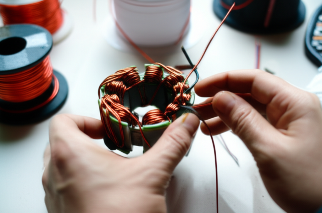
Step 5: Winding New Coils
- Calculate or confirm turns and wire gauge. If data is missing, estimate based on voltage rating, current rating, slot fill, and the original copper weight. When in doubt, reverse engineer from a surviving coil.
- Set up your coil winding machine or hand winder. Use proper winding tension. Keep turns neat and even. Loose coils shift under vibration.
- Form coils to match slot width and coil pitch. Use coil forms if available. Consistent shape makes insertion easier and reduces insulation damage.
- Track turns with a counter. Errors here cascade into performance issues like wrong speed, high current, or low torque.
Notes by motor type
- Single phase motor rewinding often involves main and auxiliary windings with different wire gauges and turns. Don’t mix them up. Respect the capacitor circuit in PSC motors.
- Three phase motor winding uses three identical phase windings displaced by 120 electrical degrees. Keep phase symmetry tight.
- DC field coil and armature rewinding are related but use different components like commutators and brushes. The principles overlap yet the details differ.
Step 6: Inserting Coils into Stator Slots
- Insert coils carefully. Use insertion tools or sticks with smooth edges. Don’t force sharp edges against slot liners.
- Push coil sides into slots evenly. Keep the coil heads orderly. Space end turns to avoid rubbing.
- Insert slot wedges to secure coils. Slot wedges lock the copper and reduce vibration.
Step 7: Connecting the Phase Windings
- Follow your original wiring diagram. Choose star (wye) or delta based on the motor’s voltage and speed requirements. Star vs delta changes line current and phase voltage.
- Make clean solder joints. Strip enamel properly. Use silicone sleeving and heat shrink tubing for insulation and strain relief.
- Attach lead wires and route them to the terminal box. Label clearly. Document the connection diagram for future maintenance.
Step 8: Lacing and Securing Windings
- Lace end turns with high temperature lacing twine. Use time-tested lacing patterns. Tight lacing keeps coils from moving and rubbing under magnetic forces.
- Add spacers or bindings where the design requires them. Uniform restraint improves reliability and reduces noise.
Step 9: Varnishing and Curing
- Impregnate windings with insulating varnish by dipping, brushing, or spraying. Vacuum pressure impregnation (VPI) gives the best penetration on larger machines.
- Preheat the stator if the varnish system requires it. Warm copper wicks varnish better.
- Bake or cure as specified by the varnish manufacturer. Don’t shortcut the schedule. Incomplete curing leads to soft coils and early failure.
Step 10: Final Reassembly
- Reinstall the rotor, new bearings, and end bells. Align carefully. Check for free rotation and uniform air gap.
- Replace seals and check the terminal box. Ensure proper clearances and secure hardware.
- If you changed the winding connection scheme or voltage rating, update the nameplate and wiring diagram.
Laminations and Core Integrity: Materials and Manufacturing Choices
Let’s step back and look at why laminations matter. The stator core is a stack of thin electrical steel sheets insulated from each other. This design breaks up eddy currents which are circulating currents induced by changing magnetic fields. Think of eddy currents like tiny whirlpools in a river. Large whirlpools steal energy and create heat. Thin, insulated laminations chop those whirlpools into small ripples that waste far less energy.
Two core loss mechanisms dominate:
- Eddy current loss: proportional to the square of lamination thickness and the square of frequency. Thinner sheets help at higher frequencies.
- Hysteresis loss: tied to the material’s B-H loop. Materials with lower coercivity switch magnetization with less energy loss.
Material considerations
- Silicon steels (M-grades): workhorses for induction motors and transformers. Silicon increases resistivity and reduces eddy currents. You’ll often hear “M19” or “M27” which indicates standard grades and thicknesses. You can explore the fundamentals of silicon steel laminations when evaluating options.
- Electrical steel laminations with optimized coatings: coatings provide interlaminar insulation and corrosion protection. The choice of coating affects stacking factor and punchability. For a broad view of materials and uses, see this primer on electrical steel laminations.
- Cobalt alloys: deliver high saturation flux density and good performance at elevated temperatures. They come with a high price tag. Aerospace and high power density machines sometimes justify the cost.
- Amorphous and nanocrystalline materials: exceptional for high frequency and low core loss yet difficult to stamp into complex shapes for standard motors. You see them more in transformers and specialty rotors or stators.
Manufacturing and assembly processes
- Stamping: best for high-volume production with consistent geometry and low cost per part. Tooling costs are significant.
- Laser cutting: excellent for prototypes, complex shapes, and low volumes. Thermal effects can create edge hardening or burrs if not controlled. This is a good method when you optimize slot shapes or test new winding patterns during development.
- Waterjet and EDM: niche methods for thick sections or special alloys where heat-affected zones would be problematic.
- Stacking and bonding: interlocking laminations work like LEGO bricks to create a rigid core without welding. Mechanical interlocks avoid heat that degrades magnetic properties. Bonded stacks use adhesives between layers for rigidity and low vibration. Welding can localize heat and increase core loss so it must be engineered carefully.
- Coatings and stacking factor: interlaminar insulation adds thickness which changes slot dimensions and stacking factor. You must account for that in slot fill and winding calculations.
Core integrity and rewind success
- Shorted laminations increase core loss which raises temperature and reduces efficiency. You can rewind perfectly and still run hot if the core is compromised.
- Core loss testing and growler checks help you catch damage early. If core loss exceeds acceptable limits, consider core repair or replacement before winding.
- Slot geometry governs magnet wire gauge and turns. Thin slot liners reduce risk of ground fault. Wedges and slot fillers stabilize the coils which reduces vibration.
Application notes
- BLDC and permanent magnet motors often use different lamination shapes and tooth designs. The lamination stack height and tooth tip geometry influence back EMF and cogging torque. If you design or source BLDC stators, a quick reference on a motor core laminations portfolio can save time during procurement.
- Some designs treat rotor and stator laminations as a matched pair. Rotor skew, slot count, and tooth shape line up with stator geometry to reduce harmonics. If you plan a full motor rebuild, it helps to review rotor core lamination options and constraints.
- If you’re evaluating a new stator supplier or plan to prototype, a general overview of stator core lamination design can help you frame the discussion on thickness, coating class, and stacking method.
Design takeaways
- Thinner laminations reduce eddy losses at higher frequencies. They cost more. Balance frequency, size, and cost.
- Better coatings improve interlaminar insulation and corrosion resistance. They can reduce stacking factor. Factor that into slot fill and winding.
- Precision cutting improves slot quality which protects insulation during coil insertion. Poor edges cut slot liners and enamel.
Testing Your Rewound Stator
You’re not done when the last knot ties off. Test the stator like you would a new motor. You’re looking for solid electrical performance and basic mechanical readiness.
Continuity test
- Use a multimeter to verify continuous circuits in each phase. No opens. No shorts across phases. Confirm that neutral points are correct if you used a star connection.
Resistance test
- Measure phase-to-phase resistance. Readings should match within a few percent. Large mismatches point to wrong turn counts or bad joints. Record the values for future trending.
Insulation resistance test (megger)
- Test each phase to ground at the proper test voltage. Follow insulation class and equipment guidance. Values should be high and stable. Watch for polarization index trends if you’re thorough.
- Dry the stator further if readings seem marginal. Moisture drags IR values down.
No-load test
- If feasible, assemble the motor and run at no load. Check current draw which should be within typical ranges for the motor size and design. Excess current suggests shorted turns or core issues.
- Listen for vibration and buzz. That often points to loose coils, poor lacing, or wedge problems.
- Measure temperature rise over a short run. Everything runs warm. Nothing should run hot.
Advanced tests for larger motors
- Surge comparison testing catches turn-to-turn faults that DC resistance won’t see.
- High potential testing (hipot) stresses insulation to confirm robustness. Use with care and follow applicable standards and safety practices.
- Vibration analysis and dynamometer tests can complete the picture when you need proof of performance.
Common Mistakes to Avoid During Stator Rewinding
A few avoidable missteps cause most rewinding headaches.
- Incorrect wire gauge or number of turns: This changes winding resistance, current, torque, and speed. Keep meticulous count. Don’t mix wire gauges unless the design calls for it.
- Damaged insulation during insertion: Nicks on enamel or torn slot liners cause ground faults. Smooth tools and patient insertion prevent this.
- Poor solder joints or connections: Cold solder joints, improper stripping, or inadequate insulation lead to opens and shorts. Use proper soldering technique and strain relief.
- Incomplete varnishing or curing: Partial impregnation leaves coils loose. Skipping curing time leaves varnish soft. Both lead to vibration issues and early failures.
- Neglecting safety: Power not locked out. No respiratory protection while varnishing. Rushed coil removal with sharp tools. Slow down and stay safe.
- Skipping core inspection: You can fix copper. You can’t ignore a bad core. Shorted laminations produce heat and reduce efficiency.
Maintaining Your Electric Motor After Rewinding
A solid rewind buys you a long service life. Smart maintenance keeps it that way.
Regular cleaning
- Keep cooling paths open. Dust and oil trap heat. Clean motor housings and internal passages when practical.
- Monitor contamination. Chemical vapors, conductive dust, and humidity degrade insulation over time.
Proper lubrication
- Replace bearings during rewind unless you just installed new ones. Follow manufacturer specs for grease type and interval. Over-greasing causes heat and seal failures.
Monitor overheating
- Check temperatures during operation. Rising temperature over time suggests load shifts, ventilation issues, or insulation decline. Thermal protection devices add insurance.
Periodic electrical checks
- Perform insulation resistance testing on a schedule. Trending IR values helps you catch moisture ingress or insulation aging early.
- Consider a preventative motor repair plan. Keep a winding data sheet on file. Build a motor maintenance schedule that includes vibration checks, bearing inspections, and simple electrical tests.
Application-specific tips
- Marine alternator rewind: salt and moisture insist on robust varnish systems and sealed connections. Consider epoxy potting in harsh zones.
- Motorcycle stator repair: compact packages run hot. Use high temperature insulation and check charging system regulators which can stress windings.
- Power tool and vacuum cleaner motor rewind: sometimes replacement is cheaper and faster. Rewind when the motor is specialized or no longer available.
- E-bike and permanent magnet motor stator: manage back EMF and heat. Slot geometry and tooth tips in BLDC motors matter as much as copper.
Conclusion: Revive Your Motor with a Successful Stator Rewind
Let’s wrap with a clear, practical takeaway you can act on today.
Your engineering takeaway
- Inspect the core first. Shorted laminations or damaged slots make a rewind risky.
- Document everything before you cut. Photos and a winding data sheet prevent guesswork.
- Match wire gauge, turn count, and winding pattern to the original or a well-justified redesign.
- Protect insulation during coil insertion. Slot liners and smooth tools matter.
- Connect, lace, varnish, and cure as a system. Each step adds reliability.
- Test thoroughly with continuity, resistance, and insulation resistance. Run a short no-load test and check current draw and temperature.
Final advice
- Rewinding can save 40–70% compared to a new motor when the core is sound and the motor matters to your operation. Industry standards and best practices show a proper rewind maintains efficiency within about 1% of original performance. Poor technique does the opposite.
- If you’re designing or sourcing stators, invest time up front on lamination choice, thickness, and slot geometry. That’s where efficiency, noise, and winding durability get decided. A concise overview of motor core laminations helps you frame the conversation with suppliers. For material fundamentals start with electrical steel laminations. When you compare lamination approaches for stators and rotors, the cross-reference to rotor core lamination is useful. You can also deepen your stator-specific knowledge with the primer on stator core lamination and dive into grades, coatings, and stacking methods. For silicon alloy benefits at different frequencies review silicon steel laminations.
Empowerment
- If you plan a DIY rewind, start with a small three phase induction motor or a simple single phase unit. Build skill with hand winding and basic varnish impregnation. Keep good notes.
- If uptime and efficiency are mission critical, engage a professional shop that follows EASA AR100 best practices and can reference NEMA and IEC standards. They’ll perform core loss testing, surge testing, and VPI when appropriate.
- If you’re specifying laminations for a new design or a replacement, bring your operating frequency, target efficiency, slot fill goals, and thermal limits to the first supplier call. You’ll get to a better answer faster.
You’ve got options. You also have a clear path. Choose the right path for your application and budget. Then execute with care and confidence.
Appendix: Quick Reference of Key Concepts and Terms
- Stator core laminations: thin, insulated electrical steel sheets stacked to form the stator. They reduce eddy current loss and shape slot geometry.
- Magnet wire: enamelled copper wire used to wind coils in slots. Wire gauge and turn count define current and voltage behavior.
- Slot insulation paper: Nomex or Mylar liners that isolate coils from the steel core.
- Insulating varnish: dielectric resin that bonds and protects windings. VPI improves penetration for larger motors.
- Star vs delta connections: two ways to connect three phase windings that affect phase voltage and line current.
- Continuity test: checks that each winding is complete and not open.
- Insulation resistance test: checks dielectric health between windings and ground.
- Growler test: detects shorts in windings and can indicate core issues in some setups.
- Hysteresis and eddy currents: two core loss mechanisms. Hysteresis depends on material properties like coercivity. Eddy currents depend on lamination thickness and frequency.
Troubleshooting snapshot
- High no-load current after rewind: check turn count, phase connections, and core integrity.
- Hot spots in the stator: inspect for shorted laminations, poor varnish penetration, or coil movement.
- Vibration and buzz: recheck wedge fit, lacing tightness, and end-turn support.
- Unequal phase resistance: look for a solder joint issue or a miscounted coil.
Decision snapshot
- Rewind when the stator core is sound and the motor is worth saving.
- Replace when core damage is significant or a new unit is cheaper and faster.
- Consult a professional when the stakes are high or the design is complex.
By now you should have a complete view of how to rewind a stator, how to evaluate whether rewinding is the right move, and how lamination choices affect both. Use this playbook to cut downtime, control costs, and protect performance.