How to Remove a Stator Without a Puller: Practical No-Puller Methods—and What They Teach Us About Motor Laminations
If you’re staring at a stuck flywheel and a stator that has to come out today, you’re not alone. DIY stator removal comes up in garages, workshops, and factory floors more often than you’d think. Maybe you don’t have the right puller on hand. Maybe the flywheel puller alternatives you tried failed. Or the flywheel threads stripped and the puller won’t bite. You still need to get that stator off safely, without wrecking the crankshaft, magnets, or the engine case. You also want to understand why the assembly fights you in the first place. More importantly, if you design motors or buy motor core laminations, you want to learn from these teardown realities. They reveal exactly how material choice and manufacturing decisions affect field service.
I’ll show you how to remove a stuck flywheel without a puller using proven, controlled methods. I’ll also connect the dots to motor lamination fundamentals. You’ll see how stator and rotor core design, insulation, and assembly processes affect heat, torque ripple, serviceability, and long-term reliability. This isn’t just a how-to. It’s a guide you can use to build better machines and write better RFQs.
In short, we’ll solve the immediate problem, explain the physics, guide you through options, and empower your next design decision.
In This Article
- Why a Puller Isn’t Always an Option
- What’s Really Going On: Stator, Flywheel, Tapered Shaft, and Laminations
- Critical Prep Before Any Attempt
- Proven No-Puller Methods That Work
- What Not to Do
- After Removal: Inspection and Reinstallation
- Design and Procurement Guide: Laminations That Build Easier-to-Service Machines
- Application Fit: BLDC vs small engines vs generators
- Procurement Checklist and Standards to Specify
- When to Seek Professional Help
- Your Engineering Takeaway
Why a Puller Isn’t Always an Option
You know the ideal advice already. Use the model-specific puller. In the real world that’s not always possible. Here’s why a puller isn’t on the bench today.
- Tool availability or cost. The correct flywheel puller can cost more than you want to spend for a one-off repair. You want cost-effective stator removal now.
- Broken or stripped puller threads. Stripped flywheel threads make a normal puller useless. You need stripped threads flywheel removal methods that don’t scar the crankshaft.
- Emergency field repair. You’re hours from a parts store. You need emergency stator replacement or emergency flywheel detachment to keep equipment running.
- Specialty configurations. Some small engines, scooters, and outboard motors use internal or external rotor designs that need a very specific puller. You need removing internal rotor without puller or external rotor removal without puller techniques right now.
- Seized assemblies. A seized flywheel or a flywheel stuck on tapered shaft resists even the right tool. You need alternate techniques that respect the taper lock.
If you’re troubleshooting “How to get flywheel off without puller” or “What if I don’t have a flywheel puller?” you’ve already felt the pain. Let’s walk through what’s going on inside the assembly so you can work smarter.
What’s Really Going On: Stator, Flywheel, Tapered Shaft, and Laminations
The flywheel seats on a tapered shaft. That taper does two jobs. It centers the flywheel on the crankshaft and it locks it in place with friction. A small Woodruff key aligns timing. When you torque the flywheel nut, you wedge the taper hard. That wedge load resists vibration and torque reversals. It also makes removal hard. Understanding flywheel taper and why flywheel gets stuck helps you select the right removal strategy.
- The taper lock. Tight torque plus a clean, dry taper creates a powerful mechanical interference. Penetrating oil and thermal tricks help break that friction.
- The Woodruff key. It establishes timing. It can bind as you begin to separate the flywheel from crankshaft. Don’t lose it.
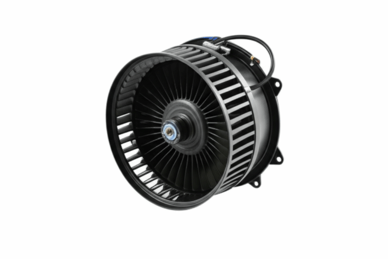
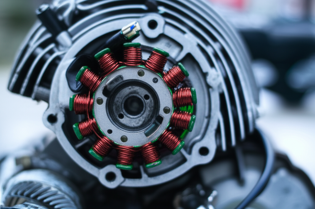
- Magnets and coils. Many small engines use a magneto. The flywheel carries permanent magnets. The stator houses coils that create the charging system or ignition trigger. Overheat the magnets and you risk demagnetization. Hammer the hub and you risk chipped magnets or coil damage. That’s why you must heat the flywheel hub and avoid heating magnets or coils directly.
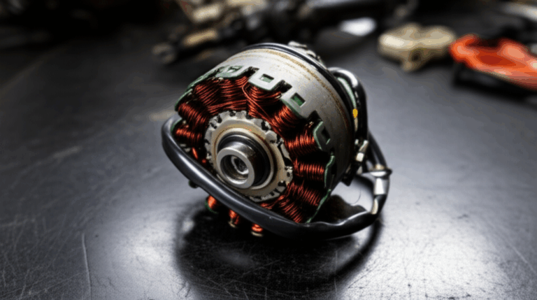
- Stator laminations. The stator core uses thin electrical steel laminations with insulation between layers. Laminations break up eddy currents, lower core loss, and improve efficiency. Think of eddy currents like small whirlpools in a river. Laminations split those whirlpools into tiny ripples. You get less loss and less heat. If you deform or chip the stator core lamination stack during removal, you create local hotspots and noise later.
If you buy or design cores, this is your world. Core loss splits into eddy current loss and hysteresis loss. Eddy current loss rises with thickness and frequency. Hysteresis loss depends on the material and its B-H curve. You tune both with grade selection and lamination thickness. You also protect the laminations with proper coatings and assembly processes. If you need a fast primer on material options and how the stack drives performance, scan this overview of electrical steel laminations.
Now let’s set up the job safely.
Critical Prep Before Any Attempt
Safety first. Disconnect the battery. Pull the spark plug wire or disable the CDI unit to avoid surprises. Wear gloves and eye protection. Secure the machine so it won’t tip.
Gather the essentials so you can perform stator removal without special tools:
- Penetrating oil for stuck flywheel joints. PB Blaster, WD-40, or Kroil all help.
- Heat source. A heat gun works. A small propane torch works if you use it carefully.
- Hammers. A dead blow or rubber mallet is safest. A small steel hammer with a brass drift for controlled taps also works.
- Pry tools. Sturdy pry bars or large flathead screwdrivers. Add wood blocks or rags to protect the engine case.
- Protection. Old inner tube pieces, card, or cloth between pry tool and case. A nut backed off to protect threads. A brass punch to avoid marring the crankshaft.
- Sockets and wrenches. Remove the flywheel nut or back it off a few threads. You may need an impact wrench to break the nut loose. If not available, learn removing flywheel nut without impact using a strap wrench or a jam tool.
- Heat sink and cooling spray. For advanced users who plan a heat and cool combo. Dry ice can work for freezing crankshaft for stator removal, though it’s uncommon in field work.
- Marking. Snap photos of stator wiring diagram removal positions. Tag electrical connectors so reassembly goes faster.
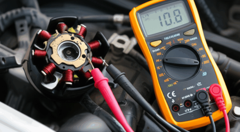
- Basic test gear. An ohm meter lets you check coil resistance after removal.
Initial steps:
1) Remove the stator cover without a puller. Drain oil or coolant if needed for your engine. Use a rubber mallet to break gaskets free. Protect the gasket face and O-ring grooves. Label every electrical connector.
2) Disconnect stator wires. Unplug the regulator/rectifier and ignition coil connectors. Move the harness clear.
3) Remove or loosen the flywheel nut. Leave the nut on a few threads. Crankshaft protection during removal matters more than speed. That nut protects the threads and your day.
You’re ready to use proven stator removal alternative methods.
Proven No-Puller Methods That Work
These are field-tested techniques for removing stubborn flywheels and stators—motorcycle stator removal no puller, ATV stator removal without special tool, lawn mower stator removal without puller, generator stator removal techniques, and dirt bike stator removal without proper tools. They also apply to marine engine stator removal and outboard motor flywheel removal without puller. Each method protects critical parts. Pick the one that best matches your setup.
Method 1: Controlled Impact and Pry
You’ll often see this described as the stator removal hammer method or the “tapping flywheel off stator” trick. It works because light, axial shock loads help the taper release.
- Back off the nut several turns. Keep it flush with or slightly above the end of the crankshaft.
- Apply penetrating oil for stuck flywheel at the hub-to-taper interface. Give it time. Ten minutes helps. Overnight helps more.
- Brace two pry points 180 degrees apart. Use wood blocks or rags between the case and the pry bar or screwdriver. Never pry on cooling fins. That’s a fast way to chip the flywheel.
- Apply gentle prying force while you tap. Use a brass punch on the nut or hub. Tap in line with the crankshaft. You want a crisp shock, not a sledgehammer swing.
- As the taper pops, the flywheel moves against the nut. Remove the nut and lift the flywheel.
Best uses: Small engine stator removal without puller. Scooter stator removal DIY. Two stroke stator removal or four stroke stator removal on engines with robust cases and good pry points. Using pry bar for stator removal and the screwdriver pry flywheel technique both work here. You just need control.
Avoid: Excessive force or wrong pry points. You can crack an engine case or bend a crank. Prevent damage during flywheel removal with protection at every contact point.
Method 2: Heat and Tap (Thermal Expansion)
You’ll also hear this called the heat and tap method stator removal or heating flywheel to remove stator. The idea is simple. You expand the flywheel hub faster than the crankshaft. The taper loses clamping force. The joint lets go.
- Remove or back off the nut as above. Keep thread protection in place.
- Apply heat to the flywheel hub only. A heat gun gives you control. A propane torch works if you keep it on the steel hub and away from magnets and coils.
- Warm the hub for 60–90 seconds. Don’t cook the magnets. Don’t damage crank seals.
- Tap the hub axially with a brass punch. Combine with gentle prying if needed.
- Re-apply penetrating oil as the joint opens. It will wick in and speed the release.
Best uses: A flywheel stuck on crankshaft with corrosion. Loosening flywheel taper lock that refuses to respond to prying alone. Outboard motors, generator engines, and small engines with heavy hubs respond well to heat gun for flywheel removal.
Risks: Heating magnets or coils directly. Overheating can de-magnetize permanent magnets or damage the ignition system. Keep the flame or blower on the hub. Not on the rim.
Method 3: DIY Bolt Puller (Improvised Flywheel Puller)
When the flywheel includes threaded extraction holes, a homemade flywheel puller substitute works well. You might see this called an improvised flywheel puller or flywheel puller alternatives DIY.
- Identify the auxiliary threaded holes on the flywheel face. Many designs use M8/M10/M12 bolt threads.
- Build a simple bridge. A flat bar or piece of angle iron works. Drill holes to match the flywheel holes. A central hole clears the crank nut or accepts a forcing screw.
- Install two or three bolts evenly into the flywheel. Tighten a turn at a time in rotation. Add a forcing screw if the setup allows. Alternately, tighten against the nut and tap the hub.
- Keep the hub oiled. Keep loads even.
Best uses: Engines designed for pullers that you don’t have. This mimics a professional puller yet costs pennies. It’s safer than pure prying. It works across motorcycles, ATVs, and generators.
Avoid: Using a three-jaw puller for flywheel (often won’t work). Those jaws grab the outer rim. They can bend fins and damage magnets. Use the extraction threads if you have them. If the threads are damaged, see the note below.
Method 4: Cooling the Crankshaft (Advanced)
Some mechanics mix heat and cold. They warm the flywheel hub and use a cooling spray on the crankshaft end. You might hear it called freezing crankshaft for stator removal. Dry ice works if you have it. It’s a niche method. Save it for stubborn cases after you’ve exhausted the other three.
If Threads Are Stripped
Stripped flywheel threads removal and broken flywheel puller alternatives demand creativity. You may combine the controlled impact and pry method with localized heat. A bearing separator under the hub can sometimes help, though you must protect the case and seals. Avoid jaw-style gear pullers on the rim. You’ll likely crack something expensive.
Scenarios Where These Methods Apply
- Motorcycle stator removal no puller. Dirt bike stator removal without proper tools. Stator plate removal no puller on older ignition systems.
- ATV stator removal without special tool. ATV flywheel removal tricks often mirror motorcycle practice.
- Generator stator removal techniques. Removing flywheel from generator engine in the field.
- Marine engine stator removal. Outboard motor flywheel removal without puller near the dock.
- Lawn mower stator removal without puller. Small engine flywheel removal methods you can do in the yard.
- Ignition system repair without special tools. Engine repair tips without specific tools when you must finish the job.
- Removing stator from crankcase and stator housing removal without puller. Removing magnets from stator or stator magnet removal methods only if your design requires it. Many designs keep magnets in the flywheel, not the stator.
A quick note on “impact method for flywheel removal” and “impact hammer flywheel removal.” Use an impact wrench to break a nut loose if needed. Do not use an impact hammer on the crankshaft end. Use controlled taps only. You want the taper to micro-separate, not the crank to mushroom.
What Kind of Success Should You Expect?
Anecdotal shop data and forum experience report good odds. Controlled impact and pry works on many small to medium engines. Heat and tap improves your chances on corroded hubs. You can expect high success rates if you go slow and protect the threads. The key lies in patience and clean technique.
What Not to Do
Skip these common mistakes stator removal approaches. They cause more pain than progress.
- Excessive force. You can bend a crankshaft. You can crack an engine case. Use gentle prying and taps. Respect the taper.
- Heating magnets or coils. You risk de-magnetization and coil damage. Avoid open flame around the magneto, CDI trigger pickup, and ignition coil area.
- Damaging threads. Always protect crankshaft threads. Keep the nut on. Use a brass punch if you need to tap.
- Wrong pry points. Don’t pry against thin casing walls. Don’t lever off sensor bosses or delicate stator plate mounts. Protect every surface with wood or rags.
- Forgetting the Woodruff key. It can fling out during separation. Catch it. Inspect it. It matters for timing.
If you ever asked “Is it safe to remove flywheel without puller?” the honest answer is yes if you use the right technique and respect the risks. When in doubt, stop and reassess. The best way to remove stator without puller is the way that leaves your engine undamaged.
After Removal: Inspection and Reinstallation
You got the flywheel off. Great. Now slow down and check everything. This is where reliability returns and future service gets easier.
- Inspect the crankshaft taper and the flywheel bore. Look for galling or corrosion. Clean both with solvent and a lint-free rag. Do not sand the taper. You want perfect mating surfaces.
- Inspect the Woodruff key. Replace it if it’s chipped or deformed. Confirm the fit in the keyway.
- Inspect the stator. Check coil leads and insulation. Use an ohm meter to verify coil resistance versus spec. Look for signs of heat. Clean the laminations gently. Cleaning stator after removal prevents future debris issues.
- Inspect magnets. Chips or cracks can throw balance off. Replace or repair as needed.
- Check the stator plate and housing. Make sure the stator plate removal no puller process didn’t bend anything. Confirm clearance to the flywheel.
- Reassemble clean. Use threadlocker on the flywheel nut per the service manual. Torque with a torque wrench to spec. Consider anti-seize on the taper only if your OEM says so. Most tapers run dry. You want friction, not slip.
- Reinstall with timing alignment. Use the key. Tighten the flywheel nut to spec. Confirm timing marks.
- Reconnect the regulator/rectifier, CDI unit, and any sensors. Confirm the stator wiring diagram removal notes you made during teardown. This saves headaches later.
If someone asks about reinstalling stator without puller, you can say the puller isn’t needed for assembly. You just seat the taper and torque to spec.
Design and Procurement Guide: Laminations That Build Easier-to-Service Machines
Let’s step back. Service realities teach design truths. The choices you make for stator and rotor cores, and the way you assemble them, affect both performance and lifetime maintainability. If you design BLDC motors, generators, or magneto-equipped small engines, this section is for you.
Engineering Fundamentals in Plain Language
- Electrical steel grades. Silicon steels lower core loss. Cobalt alloys offer higher saturation for extreme power density. Your application sets the target.
- Core loss drivers. Eddy currents scale with thickness and frequency. Hysteresis loss depends on the grade’s B-H curve. Lower coercivity materials waste less energy as the magnetic field flips.
- Lamination thickness. Thinner laminations reduce eddy currents. You get cooler operation and higher efficiency. You pay more in material and stamping tool wear. That’s the trade.
- Insulation coating. Interlaminar insulation raises resistance between layers. It stops eddy current loops that would otherwise grow and waste energy.
- Stack integrity. Burrs and poor stacking increase loss and noise. Good stacks feel like LEGO bricks clicked together. Interlocking laminations, bonding, or riveting can create rigid, quiet cores without the heat damage of welding.
If you want a quick overview of options by core location, compare stator core lamination and rotor core lamination. It helps you frame slot geometry, tooth tips, and yoke thickness choices around your magnetic circuit.
Material Considerations
- Nonoriented silicon steels (NOES, M-grades). Good general purpose choice for motors. Balance cost and performance. Available in a wide range of thicknesses and coatings. Specify per ASTM A677 where applicable.
- Grain-oriented silicon steels (GOES). Great for transformers and low-frequency devices. Less common for rotating machines. Specify per ASTM A683 for CRGO lamination core designs in transformer laminations. Save GOES for transformer lamination core work, not motor stators.
- Cobalt-iron alloys. High saturation for aerospace or high-power-density rotors. Costly. Consider when mass and temperature demands push silicon steel too hard.
- High-frequency materials. Thin gauges shine at high switching frequencies in BLDC or SRM drives. You trade thickness and stamping difficulty for lower eddy current loss.
- Coatings. Define coating class for interlaminar resistance and bonding compatibility. Check for stack bonding or weld-through requirements.
You do not have to pick this alone. A good supplier will bring loss curves, B-H data, and recommended gauge ranges for your target frequency.
Manufacturing and Assembly Processes
Manufacturing choice affects performance, cost, and serviceability.
- Stamping. Best for volume. Lowest cost per part after tooling. Watch burrs and tool wear. Plan for deburr or skiving if needed to keep stacking factor high.
- Laser cutting. Ideal for prototypes and complex low-volume runs. No upfront die cost. Heat-affected zones can increase loss if you run without a protective coating. Ask for optimized laser parameters or post processing if your loss targets are tight.
- EDM or waterjet. Niche options for specialty geometries. Slow. Clean edges with minimal thermal impact.
- Stacking methods. Interlocking tabs, bonding, riveting, or welding. Welding can add localized heat that increases loss. Bonded stacks often run quiet with excellent integrity.
- Skew and slot details. Tooth skew reduces cogging. It can complicate stacking and winding. Slot opening design affects winding process and cooling.
Want the big picture on formats and trade-offs across use cases? This quick resource on motor core laminations summarizes how stacks, coatings, and assembly flow into performance and cost.
Design-for-Service Lessons From “No-Puller” Repairs
Field repairs surface the weak points. You can make future service safer and faster.
- Provide puller threads on the flywheel. Mark thread size on the part. Nothing beats a designed-in extraction feature.
- Add robust pry pads. Give the technician a strong boss for careful levering. You’ll save cases.
- Shield windings and leads. If the stator plate sits close to the flywheel, add guards so a slip of the screwdriver doesn’t nick insulation.
- Specify coatings that tolerate brief heat. If your customer base often performs “heat and tap,” choose coatings that don’t degrade with a few short bursts from a heat gun at the hub zone.
- Control magnet placement and glue. Outboard motor flywheels and generator rotors should resist small shock loads. Robust bonding resists chip damage during light taps.
- Publish torque specs and diagrams. The best “stator replacement without puller” experiences come from clear instructions. Include diagrams for disconnecting stator wires and reassembly torque.
A little empathy for the mechanic’s reality goes a long way. You’ll reduce warranty claims. You’ll improve brand trust.
Application Fit: BLDC vs Small Engines vs Generators
“Which application is this for?” matters. Let’s match typical needs to good engineering choices.
- BLDC stators and rotors. High switching frequencies push you toward thinner gauges and lower core loss grades. Skew, slot geometry, and winding fill factor all matter. You’ll see a strong case for bonded stacks to control noise. If you’re digging into BLDC design specifically, scan what goes into a high-performance bldc stator core.
- Magneto-equipped small engines. The flywheel carries magnets. The stator lives in an oily, hot environment. Thick laminations and robust coatings survive well. Serviceability matters because field repair stator removal happens often on ATVs, lawn mowers, scooters, and dirt bikes.
- Generator stators and rotors. You balance efficiency against ruggedness. Generators see long duty cycles. Clean laminations and good ventilation keep operating temperatures down and extend service life.
- Transformers. Different beast. GOES and EI/UI formats shine here. You still manage core loss, but the stack and geometry differ vastly from a motor. You don’t apply “no puller” methods in the same way here.
Honesty builds trust. Laser cutting gives you precision and fast changes. It’s ideal for prototypes and complex, low-volume designs. Stamping gives you the best path to scale for simple geometries. Interlocking and bonding deliver quiet, rigid stacks. Welding is fast in some factories. It can raise local core loss if you don’t plan for it.
Procurement Checklist and Standards to Specify
If you’re a procurement manager or design engineer building an RFQ, give your supplier a clean target. This list will save weeks of back and forth.
- Application details. Motor type, speed range, fundamental frequency, and duty cycle.
- Electrical steel grade. Target loss at your operating flux density. Call out the standard. For example, ASTM A677 for NOES. ASTM A683 if you truly need oriented steel for a non-rotating application.
- Lamination thickness. Specify target gauge and acceptable alternates.
- Insulation coating class. Include interlaminar resistance targets. Define bonding or weld-through needs.
- Stack height and stacking factor. Call out any skew or special slot features.
- Manufacturing process. Stamped, laser-cut, or mixed. If stamped, specify burr control strategy.
- Tolerances and GD&T. Slot width, slot-to-slot variation, tooth tip tolerances, and rotor-stator concentricity. Include rotor skew if applicable.
- Assembly method. Interlocking, bonding, riveting, or welding. If bonded, specify adhesive and cure requirements.
- Test requirements. Core loss test method per IEC 60404. B-H curve data. Dimensional inspection plan. Material certifications.
- Environmental needs. Temperature range, oil exposure, vibration, and expected service interventions.
- Packaging and logistics. Stack protection, serialization, and lot traceability. PPAP or APQP if you serve automotive.
You can also reference IEEE Transactions on Magnetics for background materials, and the IEC 60404 series for magnetic testing standards. Avoid over-specifying beyond what you can measure. Tight specs without test plans cause friction and cost.
When to Seek Professional Help
For removal:
- If you worry about bending the crank or cracking the case. Don’t force it.
- If you see evidence of severe corrosion on the taper. Switch to a professional puller or a shop press with proper fixturing.
- If the ignition system sits unusually close to the flywheel and you risk heating magnets or coils. Walk away and consult a mechanic.
For lamination selection and stack design:
- If your loss targets feel aggressive. Ask for alternate grades and thicknesses.
- If your motor screams for high-frequency operation. Bring in a material specialist early.
- If you must solve noise and vibration with both electromagnetic and mechanical tools. Your lamination supplier can help you model tooth geometry and skew.
Professional advice stator removal without puller is simple. Know your limits. DIY vs professional stator removal isn’t a pride contest. It’s about protecting expensive parts.
Your Engineering Takeaway
- The taper lock keeps flywheels on tight. It will fight you. Use penetrating oil, controlled prying, and axial taps to convince it.
- Heat the hub, not the magnets. Heat and tap helps stubborn or corroded joints let go.
- Use a DIY bolt puller if your flywheel includes extraction threads. Avoid jaw pullers on the rim. They break things.
- Protect threads and cases at every step. Keep the nut on. Use wood and rags under pry points.
- After removal, inspect the taper, key, stator, and magnets. Clean mating surfaces. Torque to spec on reassembly.
- Laminations drive efficiency, heat, and noise. The right grade and thickness lower core loss. Good coatings and stacking methods protect performance.
- Design for service. Add puller threads and strong pry pads. Guard wiring. Publish torque specs. You’ll reduce field failures and inventory write-offs.
- Match process to volume and complexity. Laser for prototypes. Stamping for scale. Bonding or interlocking for quiet stacks.
- Specify standards. ASTM A677 or A683 as needed. IEC 60404 for testing. Give your supplier a clear RFQ with tolerances and test methods.
- If you’re unsure, ask early. Better questions prevent costly rework.
If you want to go deeper on material choices, start with the foundational overview of electrical steel laminations. To see how stator and rotor choices play together in complete machines, compare stator core lamination, rotor core lamination, and the broader family of motor core laminations. When you’re ready, bring your load case and constraints. A short working session with a lamination specialist can shave weeks off your design cycle.
Before we close, here’s a quick roundup that captures common “without puller” questions you might face mid-job:
- What to do if no flywheel puller. Start with controlled impact and pry. Add heat and tap. Build a DIY bolt puller if you have extraction holes. Stop if you feel the case flex.
- Best way to remove stator without puller. Heat and tap on the hub wins often. Controlled prying is next. The DIY puller wins when the flywheel gives you threads.
- Techniques for stubborn flywheel. Mix penetrating oil, heat, and measured taps. Loosen a tight flywheel slowly. You’re separating flywheel from crankshaft, not winning a strongman contest.
- How mechanics remove stators without pullers. They follow the same playbook. They also know when to stop and grab the right tool.
- Common problems with flywheel removal. Stripped threads, chipped magnets, bent fins, cracked cases. You avoid these with patience and protection.
- Stator inspection and removal. Keep wiring safe. Check insulation. Confirm resistance after the job.
You’ve got this. Use deliberate technique. Treat the assembly like the precision component it is. Build your next machine so the person in your shoes can smile when they don’t have the exact puller on hand. That’s the mark of thoughtful engineering.