How to Ohm Out an Electric Motor: A Step-by-Step Diagnostic Guide
Table of Contents
- Introduction: What “Ohming Out” Means and Why It Matters
- Understanding Motor Windings: The Heart of the Test
- Tools and Safety Gear I Trust
- Safety First: Power Off, Lockout/Tagout, and Verifying Zero Voltage
- Step-by-Step Guide: How I Ohm Out a Motor
- 5.1 Disconnect the Motor Safely
- 5.2 Set Up the Multimeter Correctly
- 5.3 Winding-to-Winding Resistance Test
- Three-Phase Motors
- Single-Phase Motors
- 5.4 Winding-to-Ground Resistance Test
- 5.5 Notes for DC, BLDC, Stepper, and Servo Motors
- Interpreting Ohm Readings: How I Decide What’s Healthy vs. Faulty
- Beyond Basic Ohming: Advanced Diagnostic Moves That Save Me Time and Money
- Real-World Examples From My Bench
- Repair, Replace, or Call a Pro: Making the Smart Next Move
- Quick Reference: My Motor Ohming Checklist
- Conclusion: Consistent Testing Extends Motor Life and Keeps You Safe
Introduction: What “Ohming Out” Means and Why It Matters
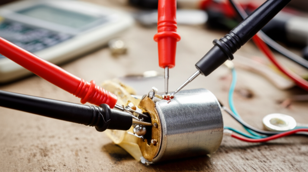
When someone asks me how to “ohm out a motor,” they want a straight answer on how to test motor windings with a multimeter. I always start with the basics. “Ohming out” means doing a motor winding resistance test. You use an ohmmeter or the ohms setting on a digital multimeter to check for open circuits, short circuits, ground faults, and unbalanced phases. The goal is simple. You want to confirm the integrity of the windings and the insulation before you power up or as part of motor troubleshooting.
Why bother? Because winding-related issues account for a big chunk of failures in electric motors. In my experience and echoed by industry studies, roughly 30–40% of electric motor failures involve winding problems like shorted turns, open circuits, or insulation breakdown that leads to ground faults. That’s huge. If you catch those early during preventative maintenance or a pre-start motor check, you can avoid downtime. Downtime gets expensive fast in industrial settings. I’ve seen reports where every minute costs thousands. You don’t need a perfect shop to prevent that. You just need a good multimeter, a steady process, and a few safety habits you never skip.
Understanding Motor Windings: The Heart of the Test
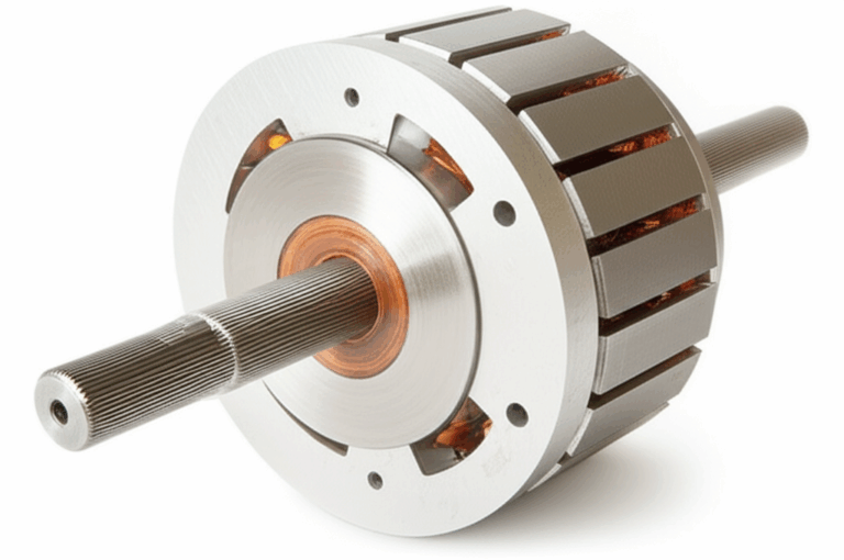
Let’s talk about what you’re measuring. The stator holds the motor windings. Those coils form the electrical paths that create a rotating magnetic field for the rotor. In a squirrel cage induction motor, the stator windings energize. The rotor responds. The health of those windings tells you a lot about the motor. Low and consistent resistance across similar windings usually indicates a healthy motor. Large differences point to trouble.
A few concepts matter here:
- Motor windings are coils of wire. They have resistance and inductance. You measure resistance with an ohmmeter. You won’t measure inductance in this test.
- Resistances are low. Many motors read in fractions of an ohm up to a few ohms depending on horsepower and voltage. Don’t panic if you see small numbers. Consistency matters more than the exact value on three-phase machines.
- Temperature changes resistance. A hot motor reads higher than a cold one. If you compare readings, try to compare apples to apples. Same ambient. Same cooldown time.
- Good insulation isolates windings from the frame. Any measurable resistance from a winding to the motor housing signals a ground fault. You should see OL or infinity on the meter for a healthy motor.
Design matters too. The quality of the stator and rotor stack influences losses and heat. When I talk with rebuild shops they often point to the role of motor core laminations and how well they’re built. Tight tolerances and good materials help reduce eddy currents. That translates to less heat which protects insulation. The same goes for the stator core lamination and the rotor core lamination since both are built from stacked electrical steel laminations. Less heat gives your windings an easier life.
Tools and Safety Gear I Trust
Here’s what I lay out before I touch a terminal:
- Digital multimeter (DMM) with a reliable ohms range. Auto-range helps but manual ranges work fine.
- Insulated test leads in good shape. No cracked insulation. No loose tips.
- PPE: safety glasses and insulated gloves. I’ll also wear hearing protection near loud equipment.
- Hand tools: screwdriver set, wrench for terminal box lugs, and wire strippers if needed.
- Notepad and pen or a notes app. I record each reading. You think you’ll remember them. You won’t after the fourth motor.
- Optional but helpful: a clamp ammeter for later current checks, and a megohmmeter (Megger) for insulation resistance tests if you need a deeper look.
- Camera phone. I take a photo of the wiring diagram inside the terminal box before I disconnect anything.
Safety First: Power Off, Lockout/Tagout, and Verifying Zero Voltage
Never skip safety. I’ve seen too many close calls when someone assumed the circuit was dead. I follow this sequence every time:
If you can’t verify isolation, you stop. You don’t test until the motor is safe to touch.
Step-by-Step Guide: How I Ohm Out a Motor
5.1 Disconnect the Motor Safely
- Turn off the breaker or disconnect. Lock it out.
- Open the motor terminal box or access point. Take a photo of the wiring and note the lead tags. On three-phase motors, you’ll see T1, T2, T3. Sometimes T4–T9 if it’s dual-voltage with wye or delta options.
- Physically disconnect the motor leads from the supply wires, contactor, or starter. Separate the leads so they don’t touch each other or the frame.
- If it’s a single-phase motor, identify C (common), R (run), and S (start) terminals. You might need the wiring diagram or the nameplate. Look for a schematic in the terminal box cover.
Self-check: Are the motor leads isolated from each other and from ground? If yes, keep going.
5.2 Set Up the Multimeter Correctly
- Insert the black lead into COM. Insert the red lead into the VΩ jack.
- Select the ohms range. Start low. Many motors will sit well below 10Ω phase-to-phase. Auto-range meters handle this smoothly.
- Touch the meter probes together. You should see near 0.0Ω. This is your meter’s lead compensation and a quick sanity check. If it reads high or jumps around, fix that first.
5.3 Winding-to-Winding Resistance Test
This is your core check. You’ll measure continuity and resistance between windings.
Three-Phase Motors
- Measure between T1 and T2. Record it.
- Measure between T2 and T3. Record it.
- Measure between T3 and T1. Record it.
What I expect:
- All three readings should be very close. A rule of thumb I use is within 5–10% deviation. Lower horsepower motors often match even tighter.
- Absolute values vary by motor size and voltage. Small motors can read a few ohms. Larger motors can land below 1Ω. Don’t fixate on the exact number unless you have a manufacturer spec or a motor winding resistance chart. Focus on balance.
Red flags:
- One pair reads significantly lower. That can indicate a turn-to-turn short. The motor will draw more current on that phase. It may run hot and trip a breaker.
- One pair reads OL or very high compared to the others. That suggests an open winding or a broken connection inside.
Single-Phase Motors
Identify and label the terminals: C (common), R (run), S (start). If the terminals aren’t obvious, use the diagram on the nameplate or inside the cover.
- Measure C to R. Record it.
- Measure C to S. Record it.
- Measure R to S. Record it.
What I expect:
- The start winding usually has higher resistance than the run winding. So C–S > C–R.
- The R–S resistance should roughly equal C–R + C–S. That’s a classic check that the windings connect correctly through the common.
- If you get OL between any pair that should be connected, you likely have an open winding or a broken lead. Check for a thermal overload device inside the motor that might be open if the motor overheated earlier.
If the motor uses an external capacitor (start or run), isolate or remove it from the circuit before you measure. A capacitor in parallel with a winding can distort resistance readings. I pop one lead off the capacitor to break the circuit during testing.
5.4 Winding-to-Ground Resistance Test
This check looks for insulation breakdown. I do it on every motor.
- Place one probe on a clean bare metal part of the motor housing. Scratch through paint if you must to get good contact.
- Touch the other probe to each motor lead one by one. On a three-phase motor hit T1, T2, T3. On a single-phase motor hit C, R, S.
What I expect:
- Your meter should show OL or infinity. That tells you the winding is fully isolated from the frame.
- Any measurable resistance means a ground fault or partial leakage path. Even a high resistance value on a standard multimeter is bad news on this test. Don’t run the motor if you see anything but OL.
If I suspect moisture, I’ll let the motor bake or dry out in a warm environment then test again. Moisture can cause leakage that looks like a ground fault. If it clears after a controlled dry out, great. If not, the insulation likely failed.
5.5 Notes for DC, BLDC, Stepper, and Servo Motors
- DC motors: Measure armature resistance between A1 and A2. It’s low. Expect fractions of an ohm on many models. Field windings (F1 to F2) will read higher depending on whether it’s a shunt or series field. You still check winding-to-ground for insulation issues.
- BLDC motors: You can ohm out the three stator phases similar to an AC three-phase motor. You expect balance between the three pairs. Rotor magnets complicate dynamic tests, not this static resistance check.
- Stepper motors: Measure phase pairs. Bipolar steppers have two separate coils. Each coil pair should match. Any open circuit or large imbalance points to a bad coil or lead.
- Servo motors: The same principles apply. Just be careful with built-in feedback devices or drives. Disconnect the motor windings from the drive before you test.
Interpreting Ohm Readings: How I Decide What’s Healthy vs. Faulty
Once I have the numbers recorded, here’s how I read them.
Normal readings (healthy motor):
- Three-phase winding-to-winding: Low resistance and tight balance. All three readings within 5–10% of each other. No surprises to ground.
- Single-phase: C–S higher than C–R. R–S matches the sum of C–R and C–S. No path to ground.
- Winding-to-ground: OL on every lead. If your meter shows any value other than OL, stop and investigate.
Abnormal readings (common motor faults):
- Open circuit on a winding (OL between points that should connect): The motor probably won’t run. Single-phase motors may just hum. Three-phase motors may trip a breaker or stall. Often you’ll find a broken lead or an internal break in the winding.
- Significantly lower resistance on one winding: That points to a shorted turn or partial short. The motor will likely overheat and draw excessive current. Protection will trip. Damage can escalate fast if you keep running it.
- Any measurable resistance to ground: That’s a ground fault or serious insulation breakdown. This is critical. Don’t energize the motor. It’s unsafe and can trip ground fault protection or shock someone.
- Unbalanced readings on a three-phase motor over ~10%: That imbalance creates unequal current and temperature in the stator. It can shorten the motor’s life and reduce efficiency.
A quick note on expected values. Typical winding resistance values run from fractions of an ohm up to a few ohms based on size and design. If you have the manufacturer’s data or a service manual, use it. If not, compare phase-to-phase balance. The balance tells you more than any absolute number in the field.
Beyond Basic Ohming: Advanced Diagnostic Moves That Save Me Time and Money
Sometimes resistance checks only get you so far. When I need more precision or I’m qualifying a critical motor, I step up the tests.
- Megohmmeter (Megger) insulation resistance test: A megger applies a higher DC voltage to see if insulation leaks under stress. For many low-voltage motors I like to see insulation resistance greater than 1 MΩ as a minimal threshold. You’ll find stricter guidelines in NEMA and IEC standards, plus manufacturer recommendations. This test catches weak insulation that a standard multimeter can’t.
- Capacitor testing on single-phase motors: If resistance checks look odd or the motor tries to start then hums, I test the start and run capacitors. Use a meter with capacitance mode or a dedicated tester. A bad capacitor can mimic winding issues.
- Current draw during operation: If the motor passes resistance tests but trips under load, I’ll power it safely and check current with a clamp meter. Compare line current to the nameplate FLA. Unbalanced current between phases points back to winding imbalances or supply issues.
- Vibration analysis and thermography: These sit outside electrical testing, yet they can reveal bearing failure vs. winding failure. Excess heat around the stator compared to the frame might hint at winding stress. Infrared inspections can spot hot spots before failure.
- Nameplate and drive compatibility: Verify voltage, frequency, and connection (delta vs. wye) before you test. Mismatch can cause heating and breakdown. If a motor runs on a VFD, confirm the drive parameters and carrier frequency recommendations. Some motors need extra protection when fed by drives.
- Trending over time: I log readings and compare them month to month. Predictive maintenance pays back. I’ve watched teams cut maintenance costs and drastically reduce breakdowns by catching small deviations early. Electrical tests like these sit at the heart of predictive maintenance for motors.
Real-World Examples From My Bench
A three-phase pump that tripped the breaker:
I got called to look at a pump motor that tripped every time the operator started it. I locked it out and ohmed it out. T1–T2 and T2–T3 looked fine. T3–T1 read much lower than the others. Winding-to-ground on T1 showed a measurable resistance that flickered. That told me two problems. A partial short and a brewing ground fault. We pulled the motor. The shop found deteriorated insulation near the slot. It likely started with heat and moisture. If the motor’s core had run cooler, the insulation might have lasted longer. Things like solid lamination stacks and good ventilation make a real difference over the long haul.
A single-phase HVAC blower that only hummed:
A homeowner’s blower motor wouldn’t start. It just hummed. I isolated the motor and ohmed C–R and C–S. Both looked plausible. R–S roughly equaled the sum. That suggested the windings were intact. I tested the start capacitor and found it way out of spec. New capacitor. Motor started right up. This one reminds me to check the simple stuff first. A start or run capacitor can throw you for a loop if you only look at windings.
A stepper motor with a dead coil:
On a small CNC machine I measured each phase pair. One coil read open. Replacement fixed it. Steppers are simple to ohm. That’s why I like them. Each pair should match. If one pair reads off or OL, you found your culprit.
Repair, Replace, or Call a Pro: Making the Smart Next Move
Here’s how I make the call after I test:
- The motor passes resistance and insulation checks. I reinstall or proceed to a powered test and monitor current draw and temperature.
- The motor shows a ground fault to the frame. I don’t energize it. That can be dangerous. It goes to a motor shop or gets replaced.
- The motor shows a clear open winding or shorted winding. I weigh repair vs. replacement. For small motors, replacement makes more sense. For larger or critical motors, a rewind can make economic sense.
- I factor in downtime costs. In many facilities, downtime costs dwarf motor prices. Predictive maintenance often cuts breakdowns by a large margin and reduces downtime hours. I’ve seen teams trim maintenance costs and boost MTBF by checking windings regularly and responding early.
You don’t have to be a motor expert to make the right call. If the readings confuse you or the motor sits on a critical system, call an electrician or a motor technician. They can run a megger test, perform surge testing, or inspect the windings and core in detail.
Quick Reference: My Motor Ohming Checklist
Use this as your motor diagnostic checklist in the field.
Pre-check
- Read the nameplate. Confirm voltage, phase, and connection type. Note NEMA or IEC standards if listed.
- Take a photo of the wiring diagram and terminal box.
Safety
- De-energize at the source. Lockout and tagout.
- Verify zero voltage with a voltmeter.
- Discharge capacitors on single-phase motors.
Isolation
- Disconnect all motor leads from the power source or drive.
- Separate and label the leads. Ensure nothing touches ground.
Multimeter setup
- Leads in COM and VΩ.
- Lowest ohms range or auto-range.
- Confirm meter reads near 0.0Ω when shorted.
Winding-to-winding tests
- Three-phase: Measure T1–T2, T2–T3, T3–T1. Record each.
- Single-phase: Measure C–R, C–S, R–S. Record each. Verify R–S ≈ C–R + C–S. Confirm start winding has higher resistance than run winding.
- DC/BLDC/Stepper: Measure coil pairs. Look for matched values and continuity.
Winding-to-ground tests
- Probe from each lead to clean motor frame metal.
- Expect OL on every lead. Any measurable resistance indicates insulation breakdown.
Interpret and act
- Balanced, low resistances with OL to ground = good.
- Open reading on a winding = broken connection or open coil.
- Unbalanced or low phase = likely shorted turns.
- Any reading to ground = ground fault. Don’t energize.
- Consider a megger test for insulation verification.
- For single-phase motors, test capacitors if symptoms and readings don’t align.
Follow-up
- Repair or replace based on findings, size, and downtime costs.
- Log your readings for trend analysis and predictive maintenance.
Conclusion: Consistent Testing Extends Motor Life and Keeps You Safe
I’ve ohmed out motors in homes, workshops, and noisy plants. The steps don’t change. Kill the power. Verify it’s dead. Isolate the windings. Measure winding-to-winding. Measure winding-to-ground. Interpret the numbers with a cool head. That simple routine catches most common motor faults before they turn into expensive problems.
If you build a habit of recording results and repeating the tests during preventative maintenance, you’ll spot small shifts early. Motors don’t fail overnight in most cases. Insulation weakens. Windings unbalance. Moisture sneaks in. Your meter will whisper the first warnings if you listen.
One last tip. Respect the materials inside these machines. Good core design and materials help motors run cooler which protects insulation and windings over the long haul. I’ve seen the difference where well-made laminations and tight stacks reduce losses and heat. That’s not just a lab story. It shows up in the field when a motor stays cool and lives longer.
You don’t need fancy gear to start. A trustworthy multimeter and a safe process take you a long way. Keep it simple. Keep it consistent. Your motors will pay you back with reliability and fewer surprises.
Internal links used:
- motor core laminations: https://sinolami.com/motor-core-laminations/
- stator core lamination: https://sinolami.com/stator-laminations/
- rotor core lamination: https://sinolami.com/rotor-laminations/
- electrical steel laminations: https://sinolami.com/electrical-steel-laminations/