How to Megger a 3‑Phase Motor: My Step‑by‑Step Guide With Real‑World Tips
Table of Contents
- Introduction: Why I Megger Every Critical 3‑Phase Motor
- What “Megger” Actually Means
- Safety First: My Non‑Negotiables Before Any Insulation Resistance Test
- Tools and Test Equipment I Use
- A Quick Primer on Motor Anatomy and Why It Matters
- Step‑By‑Step: How I Megger a 3‑Phase Motor
- Motor Preparation
- Megger Setup
- Phase‑to‑Ground Tests
- Phase‑to‑Phase Tests
- Advanced Tests: PI and DAR
- How I Read and Interpret Megger Readings
- What Counts as a Good Megger Reading
- Temperature and Humidity Effects
- Common Failure Patterns
- What I Do After the Test: Decisions, Documentation, and Next Steps
- Best Practices I Follow for Consistent, Trustworthy Results
- FAQs I Get From Techs and Managers
- Final Thoughts: Build a Habit of Predictive Maintenance
Introduction: Why I Megger Every Critical 3‑Phase Motor
The first time a production line shut down on me due to a motor failure I felt that sinking feeling in my gut. The maintenance log told a story I did not want to read. No insulation resistance test on that motor in months. Moisture in the terminal box. We lost a day of output. That was all it took. Since then I treat megger testing like a seatbelt. It is fast. It is simple. It can save your day.
In my experience megger testing is the most practical way to check the health of a motor’s insulation system. I use it for new installs. I use it for preventative maintenance. I use it when I troubleshoot ground faults or nuisance trips. When you test often you spot problems early. You avoid ground faults. You cut emergency repairs. You keep people safe.
What “Megger” Actually Means
People say “megger a motor” the way we say “Google it.” Megger is a common brand name for an insulation resistance tester. The device applies a DC voltage to the motor windings then measures leakage current to calculate resistance in megaohms. That is the essence of an insulation resistance test. It answers a simple question. How well is the winding insulation resisting current flow to ground and between phases.
You might hear related terms:
- Insulation resistance test motor
- Motor winding insulation resistance
- AC motor insulation testing
- 3‑phase motor ground fault test
You can do the same test with any reputable insulation resistance tester. Digital or analog both work. The key is using the right test voltage and following safe megger testing practices.
Safety First: My Non‑Negotiables Before Any Insulation Resistance Test
I never put leads on a 3‑phase motor until I complete five steps. These habits protect people and equipment.
1) Lockout/Tagout (LOTO)
I isolate the motor at its source. I apply LOTO on the disconnect or breaker. I try to operate the starter to verify it cannot start. I tag everything clearly.
2) Verify De‑Energized
I use a voltage tester or multimeter on all three phases to confirm zero volts. I test phase to phase and phase to ground. I test the tester before and after use. Trust but verify.
3) Discharge Stored Energy
If the motor is fed by a VFD I isolate the drive fully. I wait for the DC bus to bleed down then I confirm with a meter. VFDs can hold charge in capacitors. Do not rush this step.
4) PPE and Arc Flash Awareness
I put on eye protection and gloves at minimum. If I am testing in a Motor Control Center I assess arc flash risk. I follow site electrical safety procedures so no one gets hurt.
5) Environmental Check
I want dry and clean conditions. Moisture and contamination can skew readings and cause a scare. I wipe down the motor terminal box. I remove dust. I keep the test leads clean.
I follow these steps every time. No exceptions.
Tools and Test Equipment I Use
Here is what I keep in the kit:
- Insulation resistance tester (digital megger preferred for data logging)
- Multimeter for continuity, winding resistance, and verifying de‑energized state
- Test leads with good crocodile clips or hooks
- Basic hand tools for opening terminal boxes and isolating conductors
- Cleaning supplies: lint‑free cloths and contact cleaner
- A logbook or digital form to record results and ambient conditions
- Infrared thermometer for noting surface temperature when I trend insulation resistance vs temperature
- PPE suited to the task
I like testers that offer selectable DC voltage, PI and DAR functions, timer, and auto discharge. Auto discharge helps dump stored energy safely after the test completes. I still confirm with my meter.
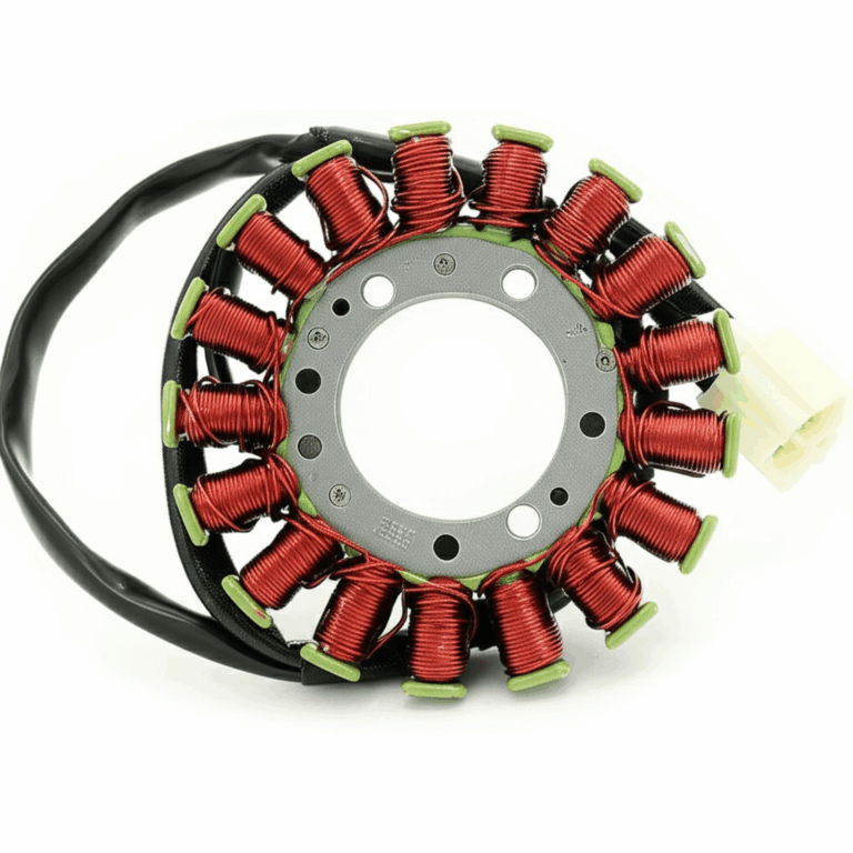
A Quick Primer on Motor Anatomy and Why It Matters
A 3‑phase AC motor has stator windings fixed in a laminated steel core and a rotor that turns inside that field. The windings sit in slots in the stator. The insulation system keeps copper from shorting to the core or to adjacent turns. That is what we are testing.
If you want a refresher on the parts that shape magnetic flux and losses take a look at high‑quality stator core lamination and how consistent stacks reduce hotspots. The rotor stack matters too. It guides the magnetic field and influences heating which affects insulation life. You can see engineered options for rotor core lamination and learn why better steel and tighter stacks reduce stray losses. If you are curious about how both halves come together this overview of motor core laminations shows the big picture from the steel to the slots. The steel itself matters because low‑loss alloys cut heat and that helps insulation. Here is a practical primer on electrical steel laminations.
Those materials do not change how you hold the test leads. They explain why heat, contamination, and aging push insulation toward failure. When windings run hot from poor ventilation or high harmonic currents the insulation dries out or cracks. When moisture and dust settle inside the terminal box leakage paths form. Your megger sees those changes in megaohms.
Internal links used so far: 4 unique links. Keep count to not exceed 5.
Step‑By‑Step: How I Megger a 3‑Phase Motor
You can megger every motor the same way if you follow a consistent process. I break it into preparation, setup, and tests. Then I record and interpret.
Motor Preparation
- Disconnect the motor from power and load
I de‑energize and mechanically decouple the motor if I can. No one should energize the circuit during testing.
- Isolate all external connections
I remove jumpers in the terminal box. I disconnect control wires that might tie windings to relays. If a VFD feeds the motor I fully isolate the motor leads from the drive terminals. I do not megger into a VFD. That can damage the drive.
- Clean the terminal box
I remove dust, oil, and moisture. I dry the area and the leads. Clean insulation gives more reliable results.
- Identify and separate windings
I mark U1, V1, W1 or T1, T2, T3 as labeled. I separate the three winding leads so each floats freely. If the motor has star or delta links I remove the links for testing. I want each phase isolated.
Megger Setup
- Select test voltage
For low‑voltage motors below 1 kV I use 500 V DC. For motors rated 1–5 kV I use 1000 V DC. For higher ratings I follow the manufacturer or IEEE recommended levels. I always confirm on the nameplate or standard.
- Verify the tester
I check the battery, zero the leads if the instrument requires it, and run a quick check on a known resistor if I have one. A flaky tester gives flaky data.
- Set the timer if available
If I plan to run PI or DAR I set up timers for 30 seconds, 60 seconds, and 10 minutes. Otherwise I use a consistent dwell time like 60 seconds for spot tests.
Phase‑to‑Ground Tests
This is the essential test. It tells you if any winding is leaking to the grounded frame.
- Connect the “Line” or positive lead to U1
- Connect the “Earth” or negative lead to a clean bare metal point on the motor frame
- Apply the test voltage
- Watch the reading climb as the insulation charges and stabilizes
- Record the value at a consistent time mark like 60 seconds
I repeat those steps for V1 to ground then W1 to ground. I always note the ambient temperature and motor surface temperature. Insulation resistance vs temperature matters for trending.
Phase‑to‑Phase Tests
Phase‑to‑phase testing checks winding‑to‑winding insulation. It helps find shorts or contamination between phases.
- Connect between U1 and V1 while W1 floats
- Apply voltage then record the resistance after stabilization
- Repeat for V1 to W1 then W1 to U1
These numbers should be high. If one pair reads lower than the others I flag it.
Advanced Tests: PI and DAR
For deeper analysis I run:
- Polarization Index (PI): 10‑minute reading divided by 1‑minute reading
- Dielectric Absorption Ratio (DAR): 60‑second reading divided by 30‑second reading
These ratios judge the quality and dryness of the insulation. Dry clean insulation shows rising resistance over time as absorption lessens. Contaminated or wet insulation shows a flat curve.
Typical interpretations based on IEEE guidance:
- PI > 4: excellent
- PI 2–4: good
- PI 1–2: fair or questionable
- PI < 1: poor
DAR follows a similar idea:
- DAR > 1.4: excellent
- DAR 1.25–1.4: good
- DAR < 1.25: questionable or poor
I use PI and DAR for older motors, motors stored for long periods, or machines exposed to moisture. If the PI is poor I consider a controlled dry‑out process before service.
How I Read and Interpret Megger Readings
You will see insulation resistance in megaohms. Higher is better but context matters. New motors often read above 100 MΩ. Older motors can still be serviceable at lower values. Temperature and humidity drive readings down. So use the standards to anchor your judgment then apply experience.
What Counts as a Good Megger Reading
Industry guidelines such as IEEE Std 43 offer a simple rule for minimum acceptable insulation resistance for rotating machinery. For motors rated below 1 kV a common guideline is:
Minimum IR in megaohms = (kV rating + 1)
So a 480 V motor has kV = 0.48. The minimum would be roughly 1.48 MΩ. That is a bare minimum. In real work I want at least 5 MΩ on a healthy low‑voltage motor in service conditions. I do not panic if a cold motor in a humid plant reads 4 MΩ. I look at the trend and compare phases.
For higher voltage machines the standard scales the expectation. You will often see test programs that call out:
- >100 MΩ: excellent for most LV motors
- 5–100 MΩ: acceptable but trend it closely
- 1–5 MΩ: investigate for moisture or contamination
- <1 MΩ: likely unfit for service until corrected
I do not treat those as hard lines in the sand. I weigh the criticality of the motor, the environment, and the trend.
Temperature and Humidity Effects
Insulation resistance roughly halves for every 10°C rise. It roughly doubles for every 10°C drop. That rule of thumb is simple and surprisingly useful. If I test at 20°C today and at 40°C next month I expect lower readings next month. I note temperature with each test then trend or correct to a reference temperature like 40°C. Many digital meggers can apply temperature correction. At minimum capture the temperature so you can make sense of the numbers.
Humidity plays tricks too. A damp motor terminal box gives artificially low readings that can rebound after a few hours in dry air or after a gentle bake. If I suspect moisture I dry and retest before I call a failure.
Common Failure Patterns
I see three common cases:
- Low resistance from phase to ground on one winding only
This hints at a localized ground path. It might be a damaged lead, contaminated terminal block, or insulation breakdown deep in the slot.
- Low resistance on all three phase‑to‑ground tests
This often means moisture or broad contamination. I clean and dry everything then retest. If it recovers I keep an eye on it and I schedule a follow‑up.
- Low resistance between phases with normal phase‑to‑ground readings
That points to winding‑to‑winding contamination or a turn‑to‑turn issue. Further testing with surge or hi‑pot might be warranted. For basic maintenance a very low phase‑to‑phase reading is a no‑go.
What I Do After the Test: Decisions, Documentation, and Next Steps
Insulation testing is only useful if you use the results. Here is my routine.
1) Document everything
I record date, location, motor nameplate data, test voltage, dwell time, all readings, ambient or surface temperature, and the environmental conditions. I add notes if I see oil, dust, or moisture. I keep both raw readings and any temperature corrected values. Data logging makes predictive maintenance possible.
2) Compare to history
I trend readings over time. Stable or rising values ease my mind. A downward trend triggers action. A step change after a flood, washdown, or outage points straight at root cause.
3) Decide on action
- Readings solid and trend stable: return to service
- Moderately low and suspected moisture: dry out then retest
- Low with no quick recovery: schedule repair or overhaul
- Very low or near zero: keep out of service until corrected
4) Restore and de‑LOTO
Once I finish and make the call I reconnect the motor, restore jumpers or links, remove LOTO following procedure, and return the system to normal. I always perform a quick continuity and phasing check before I energize.
Best Practices I Follow for Consistent, Trustworthy Results
- Keep test voltage consistent
Use the same DC voltage across tests on the same motor unless the rating changes. A different test voltage shifts readings.
- Use a standard dwell time
I prefer 60 seconds for spot IR tests. If I measure at 30 seconds today and 60 seconds next time the comparison will mislead me.
- Clean your test points
Dirty lugs cause surface leakage paths. I want bright metal for the frame connection and clean copper on leads.
- Isolate properly
I remove shorting links. I disconnect from VFDs and control wiring. I do not megger through protective devices.
- Mind the environment
Dry conditions give reliable results. If the plant is humid I note it. If the motor came from cold storage I let it acclimate.
- Consider complementary tests
A multimeter for winding resistance and continuity helps confirm open circuits. A surge test or hi‑pot test gives more depth for repair shops. For routine maintenance an insulation resistance test with PI and DAR usually suffices.
- Calibrate and check your megger
Instruments drift. I keep calibration up to date and I spot‑check against known resistors. If your tester lies your program will too.
FAQs I Get From Techs and Managers
What is the difference between a megger and a multimeter for motors?
A multimeter measures low resistance well and checks continuity. It cannot apply high DC voltage to assess insulation resistance. A megger applies a DC voltage like 500 V or 1000 V then measures leakage current to derive megaohm values. You need both tools. Use the multimeter for winding resistance and the megger for insulation resistance.
How often should I megger a motor?
Frequency depends on criticality and environment. For critical production motors I test quarterly to annually. For non‑critical motors I test every 1–3 years. I also test after repair, after a long shutdown, after flooding or contamination, and before commissioning new installs. The goal is to build a usable trend.
What voltage should I use for motor megger tests?
For motors rated below 1 kV I use 500 V DC. For 1–5 kV I use 1000 V DC. For higher voltage machines I follow manufacturer guidance or relevant standards. When in doubt check the nameplate then err on the side of the standard test voltage for that class.
Is a higher megger reading always better?
Generally yes because higher insulation resistance means less leakage. Context still matters. A very high reading that falls sharply as the motor warms could indicate dried out insulation that may crack under thermal cycling. That is why trend and PI/DAR matter.
Can I megger a motor connected to a VFD?
No. Do not apply a megger to a motor while it is connected to a VFD. You can damage the drive. Isolate the motor leads at the drive then test at the motor end. After the test verify that you reconnected correctly.
What do I do if readings are low due to moisture?
I dry the motor. I remove the end bells if practical and use gentle heat, desiccant, or a drying oven per repair shop practices. I never exceed the insulation class temperature limits. After drying I retest. If the PI improves and the IR rises the motor may return to service.
Why do phase‑to‑phase readings sometimes come in lower than phase‑to‑ground?
That can happen when contamination bridges between phase leads in the terminal box. Clean the block and the insulation sleeves then retest. If values stay low you may have inter‑winding issues that need shop diagnostics.
What is the difference between insulation resistance testing and dielectric strength testing?
Insulation resistance testing uses DC at a modest level like 500 V or 1000 V to estimate resistance. Dielectric strength or hi‑pot testing stresses the insulation at much higher voltages to verify withstand capability. Hi‑pot can be destructive if misused. I reserve it for shop tests or commissioning under a procedure.
Putting It All Together: A Case Example From My Logbook
A 40 HP 480 V motor tripped a breaker on start. I isolated it and ran a quick set of tests.
- Phase‑to‑ground at 60 seconds: U1‑G 3.6 MΩ, V1‑G 3.4 MΩ, W1‑G 3.5 MΩ at 23°C
- Phase‑to‑phase at 60 seconds: U‑V 45 MΩ, V‑W 46 MΩ, W‑U 44 MΩ
- DAR: 1.3 on phase‑to‑ground
- PI: 1.8 on phase‑to‑ground
Those numbers screamed moisture or contamination for a low‑voltage motor that usually sits above 20 MΩ in that plant. The terminal box sat under a leaky skylight and showed signs of condensation. I dried the box and leads. I applied gentle heat for two hours. I retested at 24°C.
- Phase‑to‑ground: 9.8 MΩ, 10.2 MΩ, 10.0 MΩ
- PI: 2.3
We put it back in service and scheduled a follow‑up in two weeks. The trend stayed stable after the roof repair so we called it good.
Detailed Step Checklist You Can Use On The Floor
Preparation
- LOTO complete and verified
- De‑energized confirmed with meter
- VFD isolated and DC bus discharged
- PPE on and arc flash precautions taken
- Terminal box dry and clean
Connections
- Remove links and isolate windings
- Connect L to phase lead and E to clean frame for phase‑to‑ground
- Connect L to one phase and E to another for phase‑to‑phase
- Ensure the third phase floats during phase‑to‑phase tests
Test Parameters
- Select appropriate DC voltage based on motor rating
- Use consistent dwell time like 60 seconds for spot IR
- Record at 30 s and 60 s for DAR if needed
- Record 1 min and 10 min for PI if needed
- Note motor temperature and ambient conditions
Results and Actions
- Compare readings across phases
- Compare to historical data and minimum acceptable thresholds
- If values are low dry, clean, and retest
- Document everything and decide on next steps
Common Mistakes I See and How I Avoid Them
- Meggering through a VFD or control circuit
I do not do it. I isolate at the motor and at the drive. I avoid collateral damage.
- Skipping temperature notes
I always log temperature. Without it trends lie.
- Testing with dirty or wet terminals
I clean and dry first. It saves time and avoids false negatives.
- Using the wrong test voltage
I check the motor rating and standard. I do not guess.
- Recording only “Pass/Fail”
I record actual megaohm values and time stamps. Numbers let me trend and diagnose.
- Ignoring phase‑to‑phase
I run both phase‑to‑ground and phase‑to‑phase tests. Each tells a different story.
- Forgetting to discharge
Good instruments auto discharge after the test. I still verify and I treat the motor as charged until I prove otherwise.
Why This Matters For Reliability And Cost
Insulation degradation and electrical faults account for a large slice of motor failures in industry. Bearings compete for the top spot but winding issues still drive many outages. A simple insulation resistance test program can catch early degradation and moisture ingress. You can schedule a repair during planned downtime instead of on a Friday night. I have watched plants save six figures in avoided emergency work orders and lost production. Not because fancy tools worked miracles. Because a consistent checklist and logbook kept trouble small.
Pro Tips For Special Situations
- Motors on VFDs
Pulse‑width modulation stresses insulation due to high dv/dt and common mode voltages. Your megger test still uses DC so it looks fine while the motor sees stress in service. If you run VFDs consider shaft grounding brushes and proper cable with symmetrical grounds. Keep the terminal box tight and clean to avoid leakage paths.
- Old motors with marginal readings
If the IR sits near the minimum but the PI is strong you might have a tired but clean insulation system. Trend it closely. Plan a recondition during a shutdown.
- New motors out of the crate
I always megger new motors. Shipping and storage can add moisture. A brand new machine should read sky high. If it does not I investigate before install.
- Motors after washdown or flood
Dry thoroughly. Use heaters or an oven if you have access. Test at intervals during dry‑out. Watch the DAR and PI climb. Do not rush re‑energization.
Final Thoughts: Build a Habit of Predictive Maintenance
Megger testing looks simple on paper. Clip the leads. Press the button. Read the number. The value comes from the habits behind it. Lockout and verify. Clean and isolate. Use the right voltage. Record the conditions. Read the trend. Make a call and follow through.
I do not wait for smoke or trips to tell me a story. I let the megaohms talk first. Do the same and your motors will pay you back with quiet reliable service.
Number of internal links included: 4
Unique URLs used once each:
- https://sinolami.com/stator-laminations/
- https://sinolami.com/rotor-laminations/
- https://sinolami.com/motor-core-laminations/
- https://sinolami.com/electrical-steel-laminations/