How to Make With Motor: The Engineer’s Guide to Motor Core Laminations, Materials, and Manufacturing
Every design engineer and procurement manager faces the same question at the start of a motor project. How do lamination material, thickness, and manufacturing method affect efficiency, torque density, heat, acoustic noise, and cost. You cannot push performance without getting the core right. You also cannot hit target cost without a realistic plan for tooling, tolerances, and supply.
This guide breaks the topic down in plain language. We explain the fundamentals. We compare materials and processes. Then we help you match options to your application with clear trade‑offs. Use it as a working reference during concept design, supplier selection, and DFM reviews.
If you are building DC motors, BLDCs, steppers, or servos for robotics, automation, mobility, or consumer products, you are in the right place. If you are coming from a project-based mindset and wonder how to “make with motor,” you will also learn how lamination choices underpin everything from a line follower robot to a high-efficiency BLDC for a 3D printer.
By the end you will know what to ask for, what to measure, and where the real levers are.
In This Article
- Why Lamination Material Choice Is Critical
- The Engineering Fundamentals: Core Losses and Magnetic Behavior
- Material Considerations for Motor Core Laminations
- Manufacturing and Assembly Processes That Shape Performance
- Tolerances, Geometry, and Stack Integrity
- Matching Solutions to Applications
- Testing, Standards, and Quality Assurance
- From Prototype to Production: Practical Workflow and Tools
- Troubleshooting Common Core and Motor Issues
- Safety and Reliability Considerations
- Your Engineering Takeaway
Why Lamination Material Choice Is Critical
You can optimize copper fill, windings, motor drivers, and control algorithms all day. If the magnetic circuit wastes energy in the core, you still lose efficiency and headroom. Laminations do two essential jobs.
- They provide a low reluctance path for magnetic flux. Think of magnetic permeability like sponge capacity for magnetic field lines. The higher it is, the easier the flux flows.
- They limit eddy currents by breaking up the core into thin, insulated sheets. Eddy currents act like little whirlpools in a river. Thin laminations turn one big whirlpool into many tiny ones that cannot build up much energy. Less swirling means less heat and loss.
The result shows up everywhere. Lower iron loss reduces heat rise at a given load. It boosts efficiency under partial load. It supports higher PWM switching frequencies in motor control. It even reduces acoustic noise because the core runs cooler and the laminations vibrate less when bonded well.
For most rotating machines you will work with a stator and a rotor. The stator carries slots for windings or concentrated coils. The rotor carries teeth or magnets depending on the motor type. In both parts, lamination grade, thickness, insulation coating, and stack integrity drive performance. The quality of the motor core laminations sets the ceiling for everything else.
The Engineering Fundamentals: Core Losses and Magnetic Behavior
Let’s simplify the physics without hand waving.
- Hysteresis loss: Magnetic domains in the steel flip direction as the field alternates. Each flip consumes energy due to the material’s coercivity, which is its resistance to demagnetization. Hysteresis loss scales roughly with frequency and with a power of flux density B. Better grades show lower coercivity and lower loss at a given B.
- Eddy current loss: A changing magnetic field induces currents in the steel. Those currents circulate in the plane of the laminations. They heat the material and waste power. Eddy current loss grows roughly with the square of lamination thickness at a given frequency and flux density. It also rises with the square of frequency and flux density.
- Excess or anomalous loss: At higher frequencies and in real geometries you see an extra component due to microscopic domain wall motion and local imperfections. You can treat it as a fit term in core loss models.
Two knobs matter most when you try to reduce total core loss:
1) Lamination thickness. Thinner sheets cut eddy current paths. Moving from 0.50 mm to 0.35 mm produces a noticeable reduction. High-speed machines and high-frequency applications often drop to 0.27 mm, 0.20 mm, or even 0.10 mm. At some point cost rises quickly due to material price, handling difficulty, and yield loss.
2) Material grade and microstructure. Silicon steel adds silicon to reduce hysteresis and increase resistivity. Non-oriented electrical steel spreads magnetic properties uniformly across directions which suits rotating machines. Grain-oriented steel aligns its magnetic grains for superior performance along the rolling direction which suits transformers and not rotating stators or rotors. Cobalt-iron alloys offer very high saturation flux density and low loss at high B which suits high power density machines. Amorphous and nanocrystalline alloys push loss lower at very high frequencies which suits transformers and specialized machines.
A quick analogy helps. Picture traffic flow on a multilane highway. Permeability acts like the number of lanes. More lanes let more cars pass with less resistance. Eddy currents act like cars that spin in circles in the shoulders. They do nothing useful and cause heat. Thinner laminations put up guardrails that stop those circles from forming.
Now add geometry. Teeth and slots shape flux paths and local saturation. Burrs and shorted laminations create bypasses for eddy currents. Stacking pressure and bonding quality lock the pack so it behaves like a solid, low-vibration structure without letting current flow between sheets.
Design and manufacturing must pull together here. You set the specifications. Your supplier makes them real.
Material Considerations for Motor Core Laminations
You have four broad families for rotating machines. Each one carries trade-offs in availability, cost, performance, and manufacturability.
Non-Oriented Silicon Electrical Steels (NOES)
- Use cases: General-purpose AC motors, BLDC stators, servo motors, steppers, generators. Common in M-grades like M19, M27, M36, M47 which indicate core loss classes and thickness options.
- Pros:
- Balanced magnetic properties in any direction which suits rotating fields.
- Good cost-performance ratio.
- Many thicknesses available from 0.50 mm down to 0.20 mm or thinner.
- Wide global supply base with standards such as ASTM A677 and EN 10106.
- Cons:
- Lower saturation than cobalt-iron. You may hit B limits in compact, high-torque designs.
- As thickness shrinks, handling and tooling become more challenging which can raise scrap and cost.
Grain-Oriented Silicon Steel (GOES)
- Use cases: Transformers and magnetic circuits with fixed flux direction. Not a good fit for rotating machines due to anisotropy.
- Pros:
- Very low loss in the rolling direction which suits transformer cores.
- Excellent for EI and UI core stacks in power supplies.
- Cons:
- Poor cross-grain properties that penalize rotating fields.
- You need careful orientation and cutting to maintain benefit.
If you design power supplies or on-board chargers you may also specify electrical steel laminations for transformer cores using GOES. Keep GOES out of stators and rotors.
Cobalt-Iron Alloys (Co-Fe, e.g., 49–50% Co)
- Use cases: Aerospace actuators, high-speed compressors, torque-dense servos, racing e-motors, applications that run at high B and tight thermal budgets.
- Pros:
- Very high saturation flux density that enables more torque per volume.
- Low loss at elevated flux densities compared to NOES.
- Excellent stiffness which helps rotor dynamics and slot rigidity.
- Cons:
- High material cost.
- Tighter process windows in cutting and heat treatment.
- Limited supply compared with NOES which affects procurement lead time.
Amorphous and Nanocrystalline Soft Magnet Alloys
- Use cases: High-frequency transformers and certain specialized axial-flux or slotless topologies. Rare in mainstream rotating stators or rotors because cutting and stacking remain difficult.
- Pros:
- Extremely low core loss at high frequency due to very thin ribbons and no crystalline grain boundaries.
- High resistivity and low hysteresis.
- Cons:
- Form factor challenges for slots and teeth.
- Difficult to stamp in volume which pushes teams toward bonded or wound core solutions.
Coatings and Insulation Classes
Lamination sheets come coated. The coating provides interlaminar insulation and lubricity during stamping. You need that insulation to block eddy currents between sheets. It also reduces sticking and galling during tool contact.
- Organic and inorganic coatings are classified by standards such as ASTM A976 and IEC 60404-1. Coatings balance electrical resistivity, punchability, adhesion, and thermal stability.
- Specify coating class early. Your bonding method and operating temperature drive the choice.
Thickness Selection
Use thin gauges to reduce eddy currents at higher frequency or higher electrical excitation. Use thicker gauges to cut cost and ease stamping if your motor runs at low frequency and low switching frequency. A BLDC with high PWM frequency and fast rotor speed often benefits from 0.35 mm or thinner laminations. A 50/60 Hz induction motor may use 0.50 mm with acceptable loss.
You can mix thickness and grade across product tiers. Move to 0.27 mm or better silicon steel for a premium variant. Stay with 0.35 mm for mainstream. These are common strategies in appliance and fan segments.
Manufacturing and Assembly Processes That Shape Performance
You can reach the same geometry through different processes. The path you choose sets cost, tolerance, edge quality, burr height, and magnetic degradation risk.
Stamping with Progressive Dies
- Best for high volume and stable designs.
- Low part cost after tool amortization.
- Burrs and residual stresses must be controlled. Call out maximum burr height. Typical targets run from 10–20 micrometers depending on gauge and die condition.
- Interlocking features can reduce or eliminate welding or riveting. Interlocks act like LEGO bricks that snap sheets together.
Laser Cutting
- Best for prototypes and low-volume builds with complex geometries or frequent design changes.
- Flexible and quick to iterate with no hard tooling.
- Heat-affected zones can raise local loss if you skip post-cut stress relief. You can temper or anneal to recover properties.
- Kerf width and edge taper need attention at very thin gauges.
Wire EDM
- Excellent precision with minimal heat-affected zone.
- Very slow and expensive for volume production.
- Useful for test laminations, fixtures, or specialized slots where edge quality matters.
Waterjet and Mechanical Shearing
- Generally less favored for finished laminations due to edge quality and burrs.
- Possible for rough blanks or large GO transformer shapes where losses are less sensitive.
Heat Treatment and Stress Relief
Cutting work hardens edges and introduces residual stress. Stress raises hysteresis loss. Plan for decarburization and stress relief anneal based on the material supplier’s spec. Protect coatings or recoat if necessary. This step often delivers a measurable reduction in loss, especially after laser cutting or heavy stamping.
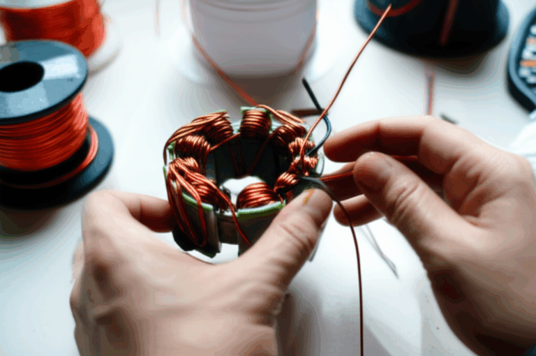
Stacking and Bonding Methods
- Interlocking tabs: Fast and low cost. Good for many rotors and stators. Verify stack factor and mechanical integrity.
- Welding (spot or TIG): Strong but introduces localized shorts and stress. Use sparingly and away from high-flux paths. Measure the impact on loss.
- Riveting or cleating: Simple, common in larger frame sizes. Plan rivet placement to minimize flux disturbance.
- Resin bonding / backlack: Sheets arrive with a thermally activated adhesive coating. You cure the stack under pressure. Bonding raises rigidity, improves vibration behavior, and can reduce audible noise. It also improves interlaminar insulation and loss.
- Gluing and hot staking: Useful in targeted areas for added stiffness.
The goal stays the same. Build a rigid stack with high interlaminar resistance and predictable geometry. A well-made stack behaves like a single unit mechanically and like many isolated sheets electrically.
If you want a deeper dive on component roles, see how stator core lamination geometry and coating create the magnetic backbone for windings and how rotor core lamination features carry slots or magnets under severe centrifugal loads.
Tolerances, Geometry, and Stack Integrity
You design magnetic circuits. You also design parts that must fit, spin, and survive loads. Keep these manufacturing realities in your drawings and models.
- Stack factor: The ratio of magnetic steel thickness to total stack height. Coatings, burrs, and air gaps reduce stack factor. Your torque prediction uses the magnetic thickness, not the nominal stack. Ask for measured stack factor per lot.
- Burr height: Burrs can short laminations at the edges. Call out a numeric limit and specify deburring where needed. Inspect with a tactile or optical method.
- OD/ID concentricity and roundness: Stators need round bores for consistent air gaps. Rotors need tight runout control to stay balanced at speed.
- Slot geometry: Tooth tips, slot openings, and fillet radii affect local flux density and cogging torque. Tight control in these regions pays off in BLDC and stepper applications.
- Shaft features and keyways in rotors: Balance cutouts and chamfers to maintain dynamic balance. Plan magnet pockets to reduce stress concentration.
- Insulation management: Coating must remain intact after stamping and stacking. Measure interlaminar resistance across the stack.
- Stack compression: Define clamping force for bonded stacks and torque for tie bolts if used. Too little pressure leads to fretting and noise. Too much pressure can deform slots and reduce stack factor.
- Surface finish: Smooth slot surfaces protect wire enamel. It reduces risk of partial discharge in high-voltage windings.
A clean drawing does not guarantee a clean build. Align your spec with a capable process and a supplier who can hit it consistently.
Matching Solutions to Applications
Different motor types and use cases push different constraints. Match material and process to the job.
BLDC and PMSM (Permanent Magnet Synchronous Motors)
- Priorities: Low iron loss at high electrical frequencies, low cogging torque, precise slot geometry, robust rotor at speed.
- Recommendations:
- Use NO silicon steel at 0.35 mm or thinner for most applications.
- Consider cobalt-iron for very high torque density or small high-speed rotors.
- Use bonded stacks for noise reduction in premium products.
- Shape tooth tips and slot openings to reduce cogging torque.
- For compact drones and robotics, review thin laminations and high-grade magnets to keep mass low.
- Resource: Review design examples and manufacturing options for a BLDC stator core.
Stepper Motors
- Priorities: High detent torque predictability, low loss under microstepping at higher PWM, precise tooth pitch.
- Recommendations:
- NO silicon steel with fine tooth geometry. Control slot and tooth burr strictly.
- Bonded stacks can improve acoustic behavior under microstepping.
- Validate core loss at your driver’s PWM frequency because DRV8825 and similar drivers use chopping that sets an effective excitation frequency.
Servo Motors
- Priorities: Torque density, thermal headroom, smoothness, low noise.
- Recommendations:
- Use premium NOES or cobalt-iron for compact, high-torque servos.
- Bonded stacks and precise slot geometry matter for ripple reduction.
- Verify dynamic losses at your control’s PWM rate.
Induction Motors and General-Purpose AC Motors
- Priorities: Cost efficiency, reliability, moderate efficiency improvements.
- Recommendations:
- NO silicon steel at 0.50 mm or 0.35 mm depending on efficiency target.
- Stamping with interlocks. Spot welds as required in low-flux areas.
- Make stack factor a controlled characteristic.
High-Frequency and Specialty Machines
- Priorities: Very low loss at high f, tight thermal budgets.
- Recommendations:
- Move to thinner NOES or cobalt-iron. Consider axial-flux topologies with soft magnetic composites only if lamination geometry becomes impractical.
- Use laser cutting with post-anneal in prototyping to stabilize losses.
Transformers and Magnetics in Your System
Your product may also need power conversion. GO silicon steel and amorphous alloys shine here. EI and UI cores build efficient transformers at line frequency. For a procurement lead, tie motor and transformer steel buys together when you can. It often improves leverage on pricing and logistics. If you need a refresher, compare EI and UI form factors and winding windows when you select a transformer lamination core.
Testing, Standards, and Quality Assurance
Trust but verify. Build your QA plan around recognized standards and practical checks.
- Magnetic property standards:
- IEC 60404 series sets definitions and test methods for magnetic materials.
- ASTM A677 covers fully processed nonoriented electrical steel spec and testing in North America.
- EN 10106 covers nonoriented electrical steel in Europe. EN 10107 covers grain-oriented steel.
- Measurement methods:
- Epstein frame per IEC 60404-2 measures core loss and B-H behavior on strip specimens.
- Single Sheet Tester per IEC 60404-3 provides loss and permeability on individual sheets.
- Permeameters can measure localized B-H curves on relevant flux paths.
- Lot certification:
- Require mill certs for chemistry, thickness, coating class, and mechanical properties.
- Ask for core loss W/kg at specific flux density and frequency, for example at 1.0 T and 50/60 Hz for screening. For rotating machines also request data at higher frequency if available.
- Validate thickness and coating weight.
- Process capability:
- Track burr height SPC. Inspect edge quality under magnification.
- Measure stack factor on witness stacks. Maintain a control chart.
- Run interlaminar resistance tests to confirm insulation integrity after stamping and stacking.
- Post-processing checks:
- If you weld or bond, retest loss on samples to gauge process impact.
- Thermal cycling and vibration testing can expose stack looseness early.
Strong QA makes the difference between a design that looks good on paper and a product that hits the field targets. It also builds confidence in your supplier relationship.
From Prototype to Production: Practical Workflow and Tools
You rarely jump straight to progressive die stamping. A smart path saves time and money.
1) Define magnetic and mechanical targets:
- Efficiency, torque, speed, allowable temperature rise.
- Electrical frequency range and PWM strategy.
- Envelope, air gap, slot fill factor.
2) Select material candidates:
- Two or three NOES grades and thicknesses as a baseline.
- A cobalt-iron option if you chase torque density or speed.
3) Prototype with flexible cutting:
- Laser cut or wire EDM the first articles. Bond small stacks. Run quick tests on a bench supply.
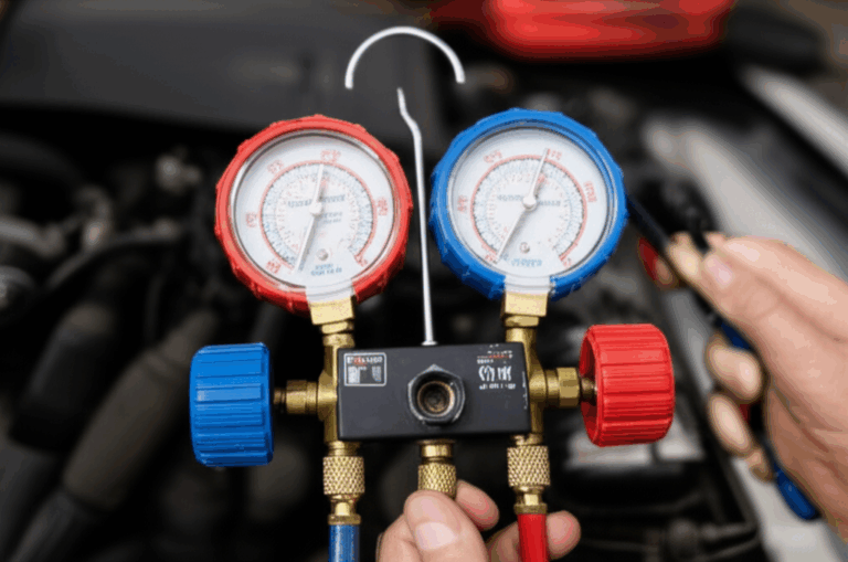
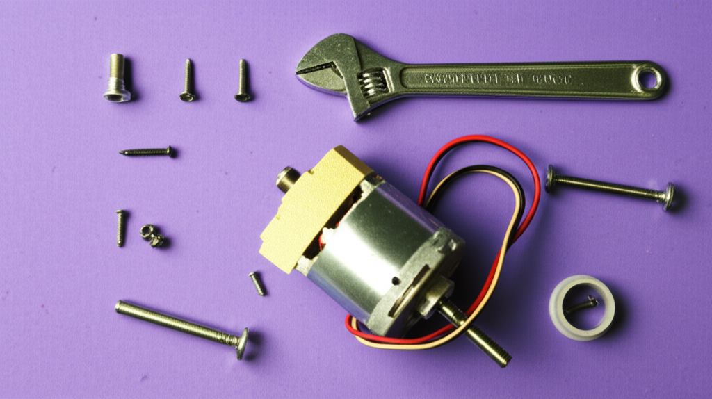
- Use an Arduino Uno or a microcontroller to exercise windings with PWM while you measure current, speed, torque, and temperature. Simple H-bridge drivers like L298N help at low power. DRV8825 or other stepper drivers let you explore microstepping. These tools are not production ready. They deliver fast learning at low cost.
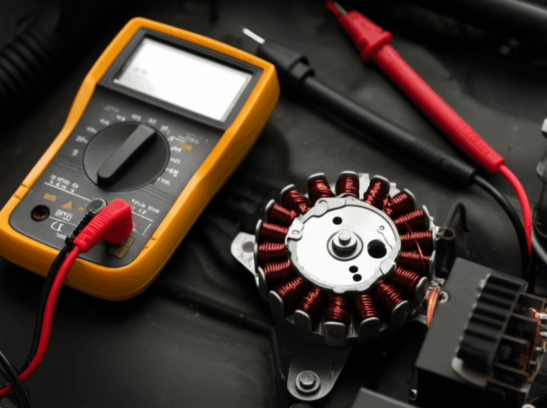
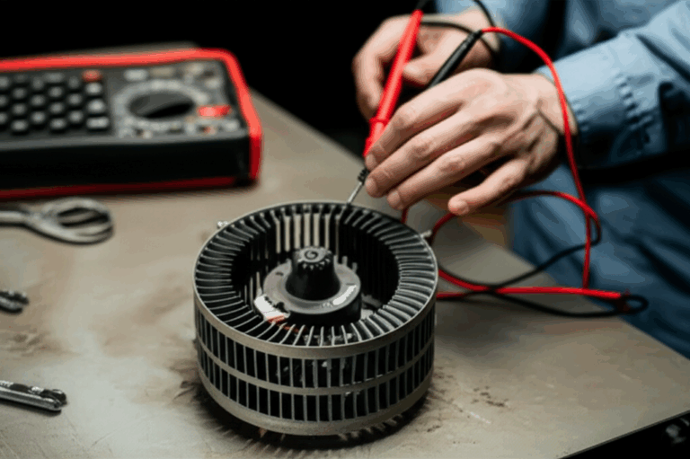
4) Instrument and test:
- Log current, voltage, and speed over PWM duty cycles. Use a multimeter and a simple tachometer. Add thermocouples to the stator yoke and teeth.
- Measure iron loss indirectly via temperature rise under no load or use loss models fed by steel data sheets. If you have access to a dynamometer, run efficiency maps.
5) Iterate geometry:
- Tune tooth tips, slot openings, and yoke thickness. Check winding window for ease of assembly. Play with skew to address cogging and torque ripple.
6) Lock material and process:
- Select the final grade and thickness. Lock coating and bonding method.
- Move to soft tooling or pilot dies. Validate burr height and stack factor.
7) Prepare for ramp:
- Approve progressive dies. Agree on maintenance and expected life.
- Set incoming inspection, acceptance criteria, and PPAP if required.
Along the way, your team may build demonstration rigs and educational prototypes for stakeholders. This is where “how to make with motor” meets engineering rigor. A few examples help frame cross-functional needs:
- Build a simple motorized test rig with a DC motor, a motor driver, and a power supply. Use a breadboard and jumper wires for sensor integration. Control speed with PWM. Log data on a Raspberry Pi. This setup helps new teammates learn motor control basics. It also helps procurement review component lead times including batteries, connectors, and voltage regulators.
- Prototype a BLDC fan blade or a motorized camera slider to visualize noise and torque ripple. Use an IR sensor or ultrasonic sensor to add position feedback. Spin quick parts with a 3D printer using PLA or ABS for fixtures. These rigs do not replace formal validation. They create shared intuition.
- Test a small pump, a conveyor belt model, or an automated stirring device to evaluate duty cycle and thermal load. Stator laminations carry the same physics in every form factor. Lessons transfer to your final product.
If you need a primer on the building blocks, skim credible overviews for core lamination stacks and then dive back into your design work.
Troubleshooting Common Core and Motor Issues
You built a stack. You wound it. You put current through it. Something went sideways. Use this checklist.
- Motor runs hot at no load:
- Core loss is high. Check material grade, thickness, and cutting method. Validate stress relief. Inspect burrs and interlaminar shorts.
- PWM frequency may be too high for the core thickness. Drop the frequency or move to thinner laminations.
- Motor vibrates or makes a loud hum:
- Loose stack or poor bonding. Increase stack pressure or use bonding. Check rivets or welds.
- Cogging torque too high. Revisit tooth geometry or skew.
- Efficiency misses the target:
- Copper loss exceeds plan due to poor slot fill. Rework winding strategy.
- Iron loss higher than modeled. Re-check steel data at your operating frequency and flux density. Verify that you annealed after laser cutting.
- Motor spins the wrong way or behaves erratically in test:
- Control wiring or phasing off. Check H-bridge wiring. Confirm sensor polarity. These are control issues, not core issues, but they come up in combined bench tests.
- Local hot spots near edges:
- Edge damage or burrs from worn tooling. Replace or service the die. Deburr and recoat if needed.
- Overheating motor driver or electronics:
- Current draw higher than expected due to iron loss or mechanical drag. Use a multimeter to isolate. Step back to a basic ON/OFF test to separate controller issues from core losses.
Troubleshooting shines a light on both design and process. Corrective action often lands in your cutting and stacking methods.
Safety and Reliability Considerations
- Electrical safety:
- Respect supply voltages and current limits. Insulate properly. Use fuses and current limiting on bench supplies.
- Manage insulation systems around the stator slots. Protect wire enamel during insertion.
- Mechanical safety:
- Treat rotors like spinning projectiles. Balance them. Lock magnets securely. Consider overspeed testing.
- Guard pinch points around gears, pulleys, and belts if you build rigs.
- Thermal management:
- Core losses add to copper losses. Heat rises fast in enclosed housings. Provide airflow or conduction paths. Validate with thermal tests.
- Process reliability:
- Keep lamination stacks clean and dry. Store steel with moisture protection. Handle sheets with gloves to avoid coating damage.
Reliability starts in small details. A clean stack today becomes a durable product tomorrow.
Bringing It Together With Real-World Uses and Prototyping Context
Your motor core choices ripple through many domains. Robotics projects for beginners, educational STEM kits, and advanced prototypes all rely on the same fundamentals.
- A line follower robot or an obstacle-avoiding robot uses DC motors or steppers. You modulate speed with PWM using drivers such as L298N or DRV8825. The core inside each motor uses NO silicon steel laminations. Better laminations cut heat and extend battery life.
- Servo motors in a small robot arm draw on precise stator geometry and low cogging. Laminations enable that precision. Your controller may be an Arduino Uno with a Bluetooth module for remote control or a Raspberry Pi on Wi‑Fi for data logging.
- 3D printers run stepper motors with fine microstepping. Laminations around the stator teeth define the torque constant and smoothness. Lower core loss helps hold torque without burning the motor at higher step rates.
- DIY micro air vehicles and mini drones use high-speed BLDCs. Thin laminations in the stator reduce eddy currents at elevated electrical frequencies. Your propeller may be plastic. The efficiency lives in the steel.
- Kinetic art, animatronics, and interactive displays all use small motors with basic H-bridge control. You connect motors to a battery, a switch, and sensors. A clean lamination stack keeps the motion quiet and cool.
Even if you prototype on a breadboard with jumper wires and a power bank, your production motor still lives or dies by its laminations.
Your Engineering Takeaway
Here is the quick roundup you can share with your team:
- Lamination thickness and steel grade control iron loss. Eddy current loss scales roughly with thickness squared at a given frequency.
- Non-oriented silicon steels fit most rotating machines. Grain-oriented steels fit transformers. Cobalt-iron raises torque density and cost.
- Cutting method and stress relief matter. Stamping suits volume. Laser and EDM suit prototyping. Anneal to recover properties.
- Bonded stacks cut noise and improve interlaminar resistance. Welding and riveting work when used thoughtfully.
- Control burrs, stack factor, slot geometry, and concentricity. These tolerances move your efficiency and noise numbers.
- Match the solution to the application. BLDCs and steppers like thin NOES and precise teeth. Servos may justify cobalt-iron. Induction motors can use thicker gauges for cost.
- Test against standards. Ask for mill certs and loss data. Run your own checks at your frequency and flux density.
- Prototype fast with flexible cutting and simple electronics. Lock your laminate decisions early to avoid surprises in PPAP and ramp.
When you want to discuss specific grades, tolerances, or stacking strategies, bring your requirements and constraints. If you need a quick orientation on part families before a sourcing call, compare options for motor core laminations. For stator geometry specifics see stator core lamination. For rotating mass constraints and magnet pocket strategies see rotor core lamination. If your system also needs optimized magnetics outside the motor, bookmark this overview of electrical steel laminations. For BLDC-focused designs scan practical notes in a BLDC stator core resource.
You do not need to be a motor core specialist to make strong decisions. You need a clear view of the physics, the process knobs, and the trade-offs. Use this guide to frame the conversation with your supplier. Set measurable targets. Ask for the right certs. Then build a motor that runs cool, efficient, and quiet.
Additional context and references you can cite in internal memos and spec sheets:
- IEC 60404 series for magnetic material definitions and test methods.
- ASTM A677 for nonoriented electrical steel.
- EN 10106 for nonoriented electrical steel and EN 10107 for grain-oriented steel.
- ASTM A976 for coating classes on electrical steels.
These documents do not tell you which motor will win your market. They help you write specs people can deliver and test.