How to Make an Electromagnetic Motor Efficient: The Engineer’s Guide to Motor Core Laminations
Every design engineer faces the same headache at some point. You need higher motor efficiency and cooler operation without blowing up the BOM or the timeline. You wonder which lamination thickness to pick. You juggle silicon steel grades. You debate stamping versus laser cutting for that prototype batch. If you are balancing performance, cost, and manufacturability your lamination decisions carry real weight. This guide breaks it down so you can move from “it depends” to “here’s our path forward.”
We will start from first principles. We will use accessible analogies that tie directly back to how an electromagnetic motor works. Then we will map those fundamentals to concrete choices for material selection, manufacturing, and assembly. You will leave with a short checklist for RFQs, testing, and supplier conversations. No fluff. Just practical engineering advice you can act on.
In This Article
- Why Lamination Choice Is Critical to Motor Performance and Cost
- Understanding Core Losses: Eddy Currents and Hysteresis
- Material Options for Laminations and When to Use Them
- Manufacturing and Assembly Processes That Matter
- Matching Laminations to Your Application and Duty Cycle
- Testing, Tolerances, and Quality Controls That Save You Later
- From DIY to Production: Translating Basic Motor Principles to Lamination Design
- Procurement Checklist and Next Steps
Part 1: The Relatable Hook — Why Lamination Choice Is Critical
If you want a simple electric motor project to spin faster you often reach for a stronger magnet, a better wire coil, or a fresh battery. In production motors you reach for better motor core laminations. Laminations do the quiet work. They shape the magnetic flux path. They reduce heat. They turn electrical energy into mechanical energy more efficiently.
Two questions sit at the core of most design reviews:
- How does lamination thickness affect motor efficiency and thermal rise at our operating frequency
- Which electrical steel grade gives us the right blend of core loss, torque density, and cost
Those are not academic questions. They impact stator slot fill, rotor saliency, magnet temperature, controller limits, and total system cost. Get laminations right and you unlock headroom for everything else. Get them wrong and you fight waste heat and performance drop for the rest of the program.
Part 2: What’s Really Going On — The Engineering Fundamentals
Let’s ground the discussion in how an electromagnetic motor works. Current in a wire creates a magnetic field. That field interacts with another magnetic field. The Lorentz force pushes the conductor and you get rotational motion. A brushed DC motor uses a commutator and brushes to switch current direction in the armature winding. A BLDC motor uses electronics to do the switching. Either way magnetic forces do the lifting.
Now the core lesson that drives lamination design.
- Eddy currents: Think of eddy currents like small, unwanted whirlpools in a river. A changing magnetic field induces circular currents inside the core material. Those currents heat the core and waste energy. Thin laminations with an insulating coating break up the whirlpools. They shorten the loops. Less current flows so less heat forms at a given frequency.
- Hysteresis loss: Magnetize a material in one direction then reverse it. You spend energy flipping the tiny magnetic domains each cycle. That energy shows up as heat. Materials with low coercivity resist being demagnetized less which means less hysteresis loss. You pick a grade with the right B-H curve for your field levels and frequency.
You can feel both mechanisms in a DIY classroom motor. If the coil takes more current yet the rotor barely spins you see heat rather than torque. In simple terms lamination thickness and material grade decide how much of your battery voltage turns into useful torque rather than a hot stator.
A few more fundamentals that steer the spec:
- Magnetic permeability: Picture permeability like how easily a sponge soaks up water. High permeability lets magnetic field lines flow through the stator and rotor with less reluctance. That improves torque for a given current.
- Stacking factor: Laminations do not stack to a solid 100 percent density because insulation and minor burrs add gaps. Stacking factor tells you how much iron is in that stack height. It matters for flux calculations and slot geometry.
- Flux density targets: Push the core too hard and you hit saturation. Torque flattens and current spikes. Your design space includes peak flux density, harmonic content, and thermal limits.
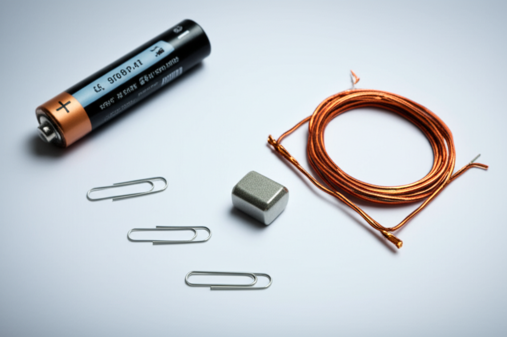
A simple homopolar motor shows eddy currents differently. You place a neodymium magnet at one end of a D-cell battery, hang a copper wire loop to touch the battery’s positive terminal, and watch it spin. That demo proves the Lorentz force in a raw way. It also shows why solid cores are a bad idea at AC. With no laminations you would turn that solid metal into a heater because eddy currents run unchecked.
Standards matter because they define how we compare materials and measure results. IEC 60404 outlines magnetic property test methods like Epstein frame and single sheet tests. ASTM A677 and ASTM A683 cover non‑oriented and grain‑oriented electrical steels. ASTM A976 defines insulation coating types. You do not need to memorize them. You just want a material spec and a test method both you and your supplier trust.
Part 3: Your Options Explained — The Guide
You have two sets of levers. Materials and manufacturing. Each choice affects performance, tolerance, cost, and lead time. Let’s walk through them with pros and cons. No silver bullets here. Just trade‑offs you can manage with eyes open.
Material Considerations
- Non‑Oriented Silicon Steels (NOES, M‑grades)
- Use for general‑purpose motors and generators from low frequency to a few kilohertz with careful thickness selection.
- Pros: Good balance of cost and performance, available in common thicknesses such as 0.50 mm, 0.35 mm, 0.27 mm, 0.20 mm. Isotropic behavior helps with rotating machinery.
- Cons: Higher core loss than premium grades at the same flux density. Thinner gauges raise cost and can challenge stacking and burr control.
- Typical applications: Industrial induction motors, brushed DC motors, BLDC stators where iron loss still matters but not at RF levels.
- Explore more: silicon steel laminations and how gauge choice influences eddy currents.
- Grain‑Oriented Silicon Steels (GOES, CRGO)
- Use for transformers and directional flux paths. The rolling direction has superior magnetic properties.
- Pros: Very low loss along the grain direction at 50/60 Hz which helps core efficiency in EI and UI shapes.
- Cons: Anisotropic. Not ideal for rotating machines where flux sweeps across directions. Cutting across grain can degrade properties.
- Typical applications: Transformers and inductors rather than rotating rotors or stators.
- Cobalt‑Iron Alloys
- Use for very high power density or high temperature environments. Aerospace and specialty traction drives often look here.
- Pros: Higher saturation flux density than silicon steels which lets you downsize or raise torque density.
- Cons: Expensive. Harder to process. You must weigh cost against performance and production scale.
- Amorphous and Nanocrystalline Alloys
- Use when you need extremely low core loss at higher frequencies. Typically for high‑frequency transformers and specialized motors or magnetic gears.
- Pros: Outstanding eddy current suppression because the structure disrupts electron paths.
- Cons: Fragile ribbons. Manufacturing complexity. Limited by available forms for rotating cores.
- Insulation Coatings
- Laminations need a thin, robust electrical insulation. ASTM A976 classifies coating types by electrical resistivity and thermal rating.
- Trade‑off: Thicker coatings cut eddy currents more but reduce stacking factor. You pick a coating that survives your bonding or welding process and your temperature class.
A quick rule of thumb for eddy currents and thickness
- Eddy current loss scales roughly with the square of thickness at a given frequency and flux density. Halve the thickness and you can expect a large drop in eddy loss. Not linear. Often worth it at higher frequencies or at high PWM ripple.
Manufacturing and Assembly Processes
- Progressive Die Stamping
- Best for high‑volume production with stable designs. Low cost per part once tools are amortized.
- Pros: Repeatable geometry, tight tolerances, high throughput, consistent burr control with tuned tooling.
- Cons: Tooling investment and lead time. Design changes late in the program can cost real money.
- Laser Cutting
- Ideal for prototyping, pilot runs, or complex geometries you may tweak. You avoid tooling cost.
- Pros: Flexible, fast iteration, good for low volumes and quick motor working models or proof‑of‑concept stator stacks.
- Cons: Heat‑affected zones can raise local loss if parameters or post‑processing fall short. Edge quality needs attention.
- Wire EDM
- Use for very tight tolerance parts or thick stacks when you need pristine edges. Common in tooling and short runs.
- Pros: Excellent edge quality and minimal thermal effects. Great for rotor or stator slots with demanding fits.
- Cons: Slow and costly for volume production.
- Stacking and Bonding Methods
- Interlocking: Think LEGO bricks. Tabs and slots in the laminations lock together and create a rigid stack without heavy heat input. Good for production motors where you want speed and repeatability.
- Welding: Spot or seam welding can secure stacks and end plates. Watch the heat input which can locally change magnetic properties and insulation.
- Adhesive bonding and backlack: Pre‑coated resins activate during heat cycles and bond laminations across the stack. You get a solid, low‑buzz core with strong mechanical integrity and no weld heat. Great for acoustic performance and reduced core vibration.
- Riveting or banding: Traditional methods still used in some rotor core lamination assemblies.
- Post‑Processing
- Stress‑relief annealing can restore magnetic properties after cutting or welding. Not all materials need it and not all coatings survive it. Coordinate with your supplier early.
- Skewing: A slight skew in rotor or stator stacks reduces cogging and acoustic noise. You trade some complexity in stacking for smoother torque.
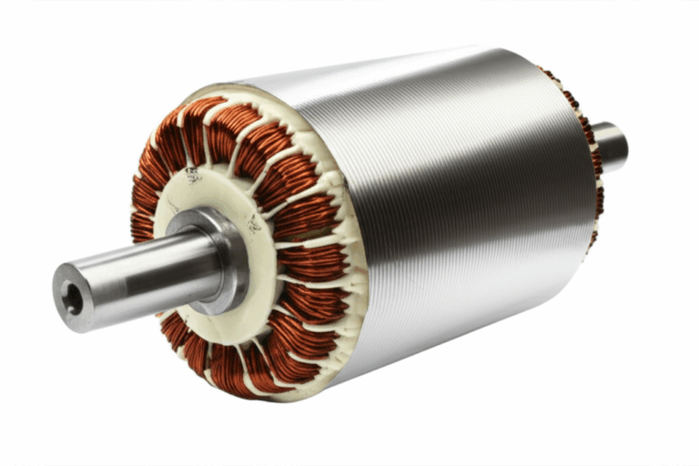
For stators and rotors the geometry decides a lot. Slot count, tooth width, back iron thickness, and rotor saliency set your magnetic circuit. The quality of the stator core lamination directly affects efficiency because it defines the flux path and slot leakage. The rotor core lamination shapes torque production, field weakening, and mechanical robustness around the shaft.
Part 4: Which Application Is This For — Finding the Best Fit
You do not pick materials in a vacuum. Tie your choice to the electrical frequency, PWM content, peak flux density, and thermal class. Then consider volume and geometry.
- Low‑frequency industrial motors at 50/60 Hz
- NOES silicon steels in common gauges such as 0.50 mm or 0.35 mm often hit the sweet spot.
- Stamping with interlock or welding supports cost‑effective scale.
- Keep an eye on stacking factor so your magnetic calculations match real iron.
- High‑speed or inverter‑driven machines with significant harmonic content
- Thinner NOES gauges like 0.27 mm or 0.20 mm cut eddy currents.
- Adhesive bonding or backlack can improve acoustic performance and reduce magnetically induced buzz.
- Evaluate losses using realistic PWM spectra rather than only sine assumptions.
- Aerospace and high power density designs
- Cobalt‑iron alloys can unlock smaller cores at the same torque. Weight savings justify cost in many cases.
- Precision cutting and careful bonding help maintain properties under high vibration and wide temperature swings.
- Transformers and choke applications near 50/60 Hz
- GOES with EI or UI geometries often wins on loss and cost.
- See how a transformer lamination core differs from rotating machines if you cross‑shop parts for a power electronics subsystem.
- Prototyping vs mass production
- Laser cutting gets you from CAD to spin test quickly. Perfect for early science fair style motor working models scaled up to engineering pilots.
- Once the design locks in consider progressive die stamping. It improves repeatability and unit cost for A, B, and C samples into SOP.
Honesty matters. Laser cutting offers exceptional precision and agility. It shines in low‑volume builds or when you plan to tweak slot geometry or magnet pocket shape. For high‑volume production of simpler geometries progressive die stamping usually delivers the best cost and consistency.
Part 5: Testing, Tolerances, and Quality Controls That Save You Later
Paper specs will not protect you if the parts arrive with heavy burrs or poor insulation. Lock down the following.
- Dimensional Tolerances
- Control slot width, tooth width, OD/ID concentricity, and stack height. Small drifts can ripple into coil fit, thermal paths, and rotor balance.
- Burr height limits matter. Excess burrs lower insulation resistance between laminations which raises eddy currents.
- Stacking Factor
- Request measured stacking factor for your stack method. Interlock, bonding, and welding each land differently.
- Magnetic Properties and Test Methods
- Reference IEC 60404 methods or equivalent for core loss and permeability. Agree on test flux densities and frequencies that reflect your operating points.
- At a minimum specify core loss at a target flux density and frequency. Include DC bias or harmonic content if relevant.
- Insulation and Coating
- Call out coating type per ASTM A976. Confirm it survives your assembly temperature and any rework steps.
- Check surface resistance if you see signs of lamination‑to‑lamination shorts during spin tests.
- Process Controls
- Confirm heat input for welding operations and any post‑process stress relief plans. Adhesive cure schedules should not degrade coating performance.
- For adhesive bonding verify bondline coverage and acoustic performance. A solid bond lowers noise and avoids micro‑movement.
- Prototype to Production Consistency
- If you switch from laser cut prototypes to stamped parts validate core loss again. Edge quality and stress can shift results.
- Document your magnets, current flow, and test rig since small changes can skew data. Treat it like a controlled science experiment rather than a one‑off demo.
Part 6: From DIY to Production — Translating Basic Motor Principles to Lamination Design
You may remember winding a wire coil for a school motor and placing a permanent magnet under it. That simple electromagnetic motor science fair project teaches a lot. It shows how current flow produces a magnetic field. It reveals why magnet placement and polarity matter. It proves that commutator function and brushes in a DC motor control current direction in the armature. Good lamination design builds on the same physics with grown‑up constraints.
Bridge the concepts:
- A wire coil for a motor creates the magnetic field you need. In production the stator teeth focus that field where it does work. Better laminations guide the magnetic field lines and raise motor torque without raising current.
- Magnet placement in a motor and magnetic poles set the interaction with the stator. Rotor laminations shape the flux path for permanent magnets or for induction bars.
- The battery powered motor circuit in a project becomes an inverter or DC supply with control electronics. The stator core must handle not only fundamental frequency but also PWM harmonics.
- If a motor does not spin in the classroom you check coil insulation removal, loose connections, and balance. In production you check insulation coatings, burrs, poor electrical contact between laminations, and coil fit. You just use a multimeter and an LCR meter rather than alligator clips and sandpaper.
Let’s connect a few more familiar terms to design decisions engineers make daily:
- Electromagnetism 101: Current creates magnetism and magnetic forces create motion. Laminations keep unwanted eddy currents in check so that more of your electrical energy turns into mechanical energy and less into heat.
- Faraday’s law of induction: A changing magnetic field induces voltage. It explains why torque ripples can induce small currents in conductive parts and why you choose insulating adhesives for backlack cores to reduce circulating paths.
- Lorentz force: The same force that spins a homopolar motor drives your rotor. You refine this with better flux paths and lower reluctance.
- Oersted’s experiment: A wire carrying current deflects a compass. You use that principle when you shape stator teeth to concentrate fields where they drive the rotor.
Even the “troubleshooting DIY motor” list maps cleanly to engineering root causes:
- No current flow: Dead battery in the classroom. In production it becomes a dead cell in your pack or a failed phase. It can also be a lamination insulation short raising losses so much that your test current never reaches target.
- Incorrect magnet placement or polarity: A flipped rotor magnet in a BLDC stator turns into lower back‑EMF and noisy torque. Set magnet orientation right and use proper fixtures.
- Coil not balanced: Uneven winding raises friction and rubs supports in a demo. Slot fill and end turn geometry in a stator do the same when you scale up. Balance matters for rotors too since imbalance can ruin bearings.
- Insufficient power: Weak battery vs weak bus. In both cases torque collapses. For cores a material with high loss will draw current that turns into heat rather than speed.
You can even use quick classroom style experiments to build team intuition during early design:
- Wind a simple coil, drive it with low voltage DC, and measure temperature and RPM with different magnet strengths. You will see how magnetic field strength and coil turns influence torque and speed.
- Swap magnet wire gauge and watch current flow and resistance change. Then translate that to copper slot fill in the stator for your final machine.
- Move magnets closer or farther. You will feel the change in magnetic forces and see why air gap control and rotor concentricity matter.
These hands‑on analogies sound simple. They stick. They also make design reviews sharper because everyone shares the same mental picture.
Part 7: Keyword‑Driven Practical Notes Engineers Ask All the Time
Engineers and procurement teams ask variants of the same questions. Let’s answer them briskly and tie back to lamination decisions.
- What causes motor rotation and how do laminations help
- Interaction between the stator’s generated magnetic field and rotor magnetic poles creates torque. Laminations improve magnetic permeability and reduce eddy currents so more field reaches the rotor at the same current.
- How do I increase motor efficiency in a brushed DC or BLDC stator core
- Use thinner laminations at higher frequencies or with strong PWM to reduce eddy current loss. Choose a material with lower hysteresis loss at your flux density. Improve coil slot fill. Reduce air gap. Verify stacking factor to match design assumptions.
- Which battery voltage for a small motor vs a production machine
- Voltage sets back‑EMF and speed in DC machines. In AC machines voltage relates to flux. For DIY projects a D‑cell battery or a small power supply works for demos. For production use your inverter’s DC link and confirm thermal headroom at operating current.
- How to balance a motor armature and a rotor stack
- For DIY motors you bend wire ends and rebalance by hand. For production use dynamic balancing on the rotor assembly. Control stack alignment, shaft runout, and magnet placement to keep vibration within spec.
- Best materials for a motor coil and connections
- Enamel magnet wire with proper insulation builds reliable armature windings. In production stator coils use enamel wire with thermal class ratings matched to service. Alligator clips teach contact resistance in a demo. In production use crimping and soldering processes with defined pull strength and resistance limits.
- How to mount a simple motor vs mounting a stator
- A block of wood or cardboard base works for science projects. In production you mount the stator core into a housing with precise fits, insulation sleeves, and thermal compound or resin potting as needed.
- How to troubleshoot when a motor does not spin
- DIY: remove enamel from one end of the coil fully and half‑insulate the other so the commutator function works. Production: check electrical continuity, insulation resistance, wrong magnet polarity, shorted turns, burr‑induced shorts, and mechanical rub.
- Which magnet type for motors
- Neodymium magnets offer high energy density for compact BLDC motors. Ferrites cost less and suit lower power density. Your lamination material must carry the flux without saturation.
You will notice how many simple phrases cover complex choices: magnet polarity, current direction, rotational direction, torque, motor efficiency. The physics stay the same across scales. Your lamination spec just dictates how much of that physics helps you rather than hurts you.
Part 8: Sourcing Smart — Procurement Checklist You Can Use Today
When you issue an RFQ for laminations or complete stator stacks include this data. It speeds quotes and reduces surprises.
- Application and operating points
- Machine type: BLDC stator core, induction motor, brushed DC motor, generator.
- Electrical frequency range and PWM switching frequency.
- Target flux density and expected thermal class.
- Material
- Grade and thickness options. Example: NOES M19 at 0.35 mm and 0.27 mm for comparison.
- Insulation coating per ASTM A976 with target surface resistance and temperature limits.
- Geometry and tolerances
- OD, ID, slot shapes, tooth width, air gap target. Provide fully dimensioned drawings and STEP files.
- Burr height limits. Stacking factor expectations.
- Manufacturing process
- Preferred cutting method for prototype and production. Stamping, laser, or EDM.
- Stacking method: interlock, adhesive bonding or backlack, welding, riveting, banding.
- Skew angle if required.
- Quality and test requirements
- Dimensional inspection plan. Magnetic property validation per IEC 60404 method and target points.
- Visual criteria for insulation integrity and edge quality. Acoustic targets if bonding to reduce buzz.
- Volume and logistics
- Pilot quantities and ramp plan. Packaging to protect insulation. Any ESD or moisture controls.
You will get sharper quotes when you communicate intent. You also frame supplier discussions around engineering constraints rather than just price.
Part 9: Where Internal Expertise Meets Supplier Capability
You do not need to become a full‑time metallurgist to choose laminations well. You do need a partner who can explain trade‑offs and show data at your frequencies and flux densities. Look for suppliers who publish capabilities around electrical steel laminations, share examples of stator core lamination, and discuss rotor core lamination challenges like skew, magnet pockets, and balance correction. For broader context on options and stack construction see resources on motor core laminations and the role of silicon steel laminations.
Standards like IEC 60404 and ASTM A677 give you a common language. Internal tests like Epstein frame or single sheet tests let you compare real lots under your conditions. That combination builds confidence.
Part 10: Your Engineering Takeaway — Summarized and Actionable
Key points to remember
- Eddy currents behave like electrical whirlpools. Thinner, insulated laminations break them up and cut heat.
- Hysteresis loss depends on material coercivity and the B‑H loop. Pick a grade that matches your flux density and frequency.
- NOES silicon steels cover most rotating machines. GOES suits transformers. Cobalt‑iron helps when you chase power density or temperature margins.
- Stamping rules high‑volume runs. Laser cutting accelerates prototypes. EDM wins on precision.
- Bonding methods matter. Interlock is fast. Welding needs heat control. Backlack bonding improves acoustic performance and core rigidity.
- Validate with the right tests. Control burrs, stacking factor, coating integrity, and dimensional tolerances. Align prototype and production processes to avoid surprises.
Next steps you can take this week
- Define your operating frequency, flux density, and PWM profile. Use them to set lamination thickness candidates.
- Shortlist two material grades and two thicknesses. Request data at your target operating points from suppliers.
- Build a quick A/B prototype set. Laser cut parts for speed. Instrument them for torque, temperature rise, and no‑load losses.
- Align on a stacking method and bonding approach that fits your acoustic and vibration targets.
- Lock an RFQ package with drawings, tolerances, coating spec, target magnetic properties, and volume plan.
If you want a sounding board run your constraints by a lamination specialist. An early 30‑minute technical review can save weeks of iteration and trim real cost from the final design.
Appendix: Cross‑walk From Educational Motor Terms to Production Decisions
Use this quick glossary to relate familiar concepts from simple motor demonstrations to lamination choices in real machines. It keeps teams aligned from intern to chief engineer.
- Simple electric motor project and educational motor model
- A hands‑on demo that shows how current flow in electric motor windings creates a magnetic field and torque. Production cores take that same principle and optimize magnetic path, efficiency, and thermal behavior.
- DIY electromagnetic motor instructions and step‑by‑step motor construction
- Sets up coil winding, magnet placement, and battery connections. In production you define coil turns and slot geometry, permanent magnet placement, and the electrical circuit that drives the stator.
- Components of a simple motor: coil, magnet, battery, brushes in DC motor, commutator function in motor
- Map to stator, rotor, power electronics, and feedback sensors in BLDC machines. Laminations shape stator teeth and rotor back iron so those components interact efficiently.
- Materials for homemade motor and best materials for motor coil
- Magnet wire and neodymium magnets in demos become enamel wire and specified magnet grades in products. Laminations rely on silicon steel with defined electrical resistance and magnetic properties.
- How to make a homopolar motor and motor wiring diagram simple
- A fun proof of Lorentz force. It teaches why magnetic field lines and current direction determine rotational direction and torque.
- Troubleshooting DIY motor: motor does not spin, no current flow, incorrect magnet polarity, coil not balanced, insufficient power
- Mirrors production issues like lamination shorts, wrong magnet orientation, poor rotor balance, and under‑voltage conditions.
- Increase motor speed DIY and making a powerful small motor
- In production you lower core loss, reduce air gap, improve slot fill, and manage field weakening for speed. You do not just raise voltage because thermal limits still rule.
- Safety tips for motor building
- Eye protection and careful handling of wires and hot glue in the lab. In production you manage electrical safety, insulation integrity, and rotating hardware with guarding and process controls.
- Physics behind electric motors and principles of operation electric motor
- Electromagnetism, magnetic forces in motors, and Faraday’s law of induction remain your foundation. Laminations let you shape those fields while minimizing losses.
- Magnet polarity motor and magnetic field lines motor
- Correct orientation of north and south pole magnets and a clean flux path through the stator teeth and back iron drive torque. Laminations keep that path low loss.
- Power source for DIY motor and battery requirements for motor
- D‑cell batteries in demos. DC links and inverters in products. Confirm your voltage headroom and current limits then size laminations accordingly.
- Motor performance testing and motor efficiency DIY
- RPM and temperature checks in the lab translate to dynamometer testing, loss mapping, and core loss measurement to IEC 60404 at several flux densities.
- Motor base construction and mount a simple motor
- A small block of wood in class evolves into a machined housing with precise fits for stator OD and rotor bearings. It all comes back to alignment and consistent air gap.
- Magnet wire gauge for motor and insulated wire for motor
- Wire gauge changes resistance and current which changes copper loss. Laminations should not add avoidable iron loss so your copper produces torque rather than heat.
- Armature winding for motor and winding a solenoid for motor
- Winding technique drives slot fill and thermal behavior. Stator tooth shape from laminations drives how much copper you can pack and how efficiently you use it.
- Motor shaft construction, motor bearings simple, and how to balance a motor armature
- Mechanical integrity and balance matter because vibration wastes energy and wears parts. Rotor lamination alignment around the shaft helps you hit balance targets.
- Classroom motor experiment and STEM education
- Those projects build intuition that helps real design choices. They show why lamination thickness and insulation change outcomes in a measurable way.
If you keep this cross‑walk in mind you will explain lamination trade‑offs to any audience. From a science fair to a design review everyone can see why thinner insulated laminations raise efficiency and reduce heat.
Final Word
Clarity beats complexity. You do not need a perfect lamination on day one. You need a good short list and a plan to test it against your real waveforms. Use the fundamentals to frame choices. Use prototypes to validate. Then lock production with tight tolerances and the right bonding method. When you do that your motor will spin cooler, deliver higher torque per amp, and live longer. That is how you turn a simple electromagnetic idea into a reliable machine.
If you want to talk through options with an engineering partner, share your operating points, geometry, and volumes. We can help you compare materials, thicknesses, and stack methods so your next build moves from “it depends” to “let’s go.”