How to Identify Stator Wires: Your Comprehensive Guide to Motor Wiring
Every engineer has stared at a handful of unmarked motor leads and wondered which one does what. You can’t power up until you identify stator wires correctly. You don’t want guesswork either because miswiring can burn a winding, trip protection, or spin a machine the wrong way. This guide walks you through how to identify stator wires on single‑phase, three‑phase, and BLDC motors with practical tests that work in the lab and on the plant floor. You’ll get safety steps, clear procedures, and the reasoning behind each move, so you can diagnose issues, reconnect with confidence, and cut downtime.
Why start here if your world centers on laminations and motor cores? Because reliable wire identification depends on the quality of the stator winding, the uniformity of its resistance, and the integrity of its insulation. Those factors tie directly to the design and manufacturing of the stator core lamination stack. You’ll see where material and process choices show up in your test results, which helps procurement and design teams make smarter decisions upstream.
In plain terms, you’ll learn the “what,” “why,” and “how.” Then you’ll leave with checklists and next steps you can apply right away.
In This Article
- Why correct stator wire identification matters
- The tools you need for safe, accurate testing
- Safety first: de‑energize and verify
- Stator winding basics: resistance and continuity
- Step‑by‑step methods by motor type
- Interpreting results and making the call
- Advanced tips, materials, and manufacturing context
- Special cases by application plus FAQs
- Your engineering takeaway
Introduction: Why Correct Stator Wire Identification Is Essential
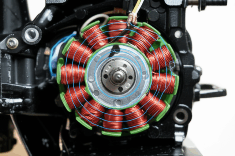
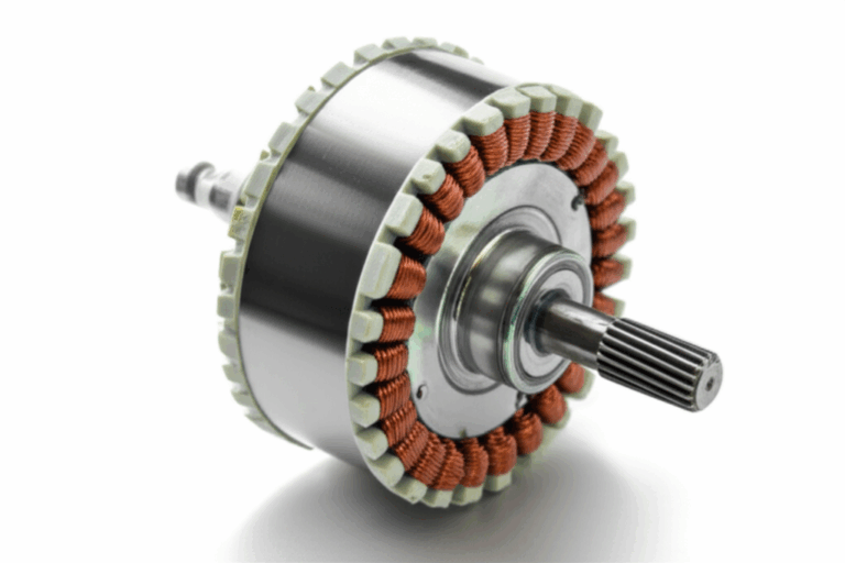
What is a stator? It’s the stationary magnetic core and its windings that create the rotating magnetic field in the motor. Those windings terminate in stator wires or leads. You need to identify each lead correctly to connect power, measure health, and troubleshoot faults.
Common scenarios that put you here:
- You’re troubleshooting a motor that hums but won’t start.
- You’re replacing a failed stator and need to reconnect run, start, and common windings.
- You’re inspecting a generator or alternator stator after a fault.
- You’ve got a BLDC motor with phase and Hall leads, and the labels are gone.
- You’re integrating a motor into a product and you need to verify the manufacturer’s diagram matches what’s in hand.
Accuracy isn’t optional. Misidentification can overheat a start winding, spin a machine backward, or trip a drive. Best case, you lose time. Worst case, you lose a motor and maybe a process.
Here’s what you’ll learn in this guide:
- How to test stator windings with a multimeter using resistance and continuity checks.
- How to identify run and start windings on a single‑phase motor.
- How to identify 3‑phase motor wires.
- How to verify BLDC phase leads.
- How to interpret readings and decide what to repair or replace.
- How lamination materials and stack construction influence consistent, reliable test results.
Gather Your Essential Tools for Safe Testing
You don’t need a truck full of gear to identify motor leads. You do need reliable basics, used correctly.
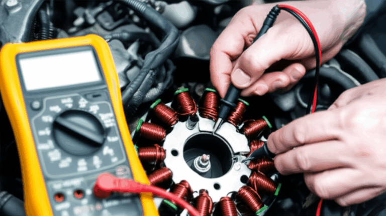
- Multimeter: Your cornerstone tool. You’ll use Ohms for resistance and a continuity/diode function for quick checks. A meter with a low‑ohm capability helps on BLDC motors and larger 3‑phase windings.
- Continuity tester: Handy for quick open/closed checks when speed matters.
- Wiring diagram: If you have it, you can confirm naming conventions and color codes. Many diagrams include motor terminal block identification and show run, start, and common or W1–U1–V1 style designations.
- Test leads and probes: Use sharp, clean tips. Clip leads help when you work alone.
- Basic cleaning supplies: Scotch‑Brite, isopropyl alcohol, and a rag. Clean terminations give you better contact which gives you better data.
- PPE: Safety glasses and insulated gloves. You’ll work around energized cabinets and enclosures even if the motor is de‑energized.
- Optional tools: A clamp ammeter for load checks after wiring, a megohmmeter (megger) for insulation resistance, and a tone tracer for long cable runs.
Safety First: Critical Precautions Before Testing Any Wires
Treat every lead as live until you prove otherwise. Safety comes first because a 5‑minute check prevents a lifetime mistake.
- De‑energize the motor. Use lockout/tagout. Open the disconnect. Lock it. Tag it.
- Verify zero energy state. Test the supply terminals with your multimeter. Confirm no voltage is present phase‑to‑phase and phase‑to‑ground. Test your meter on a known live source before and after to prove function.
- Discharge capacitors. Single‑phase motors with start or run capacitors can hold a charge. Safely discharge per manufacturer guidance or use a bleeder resistor across the terminals.
- Work in a dry environment. Moisture changes resistance readings and creates shock risk.
- Respect arc flash boundaries. Follow NFPA 70E or equivalent site policy.
If you need to perform insulation resistance testing, follow IEEE Std 43 for test methods and minimum values by motor voltage class.
Understanding Stator Winding Basics for Identification
You’re about to measure electrical fingerprints. Here’s what you’ll look for and why it works.
- A stator winding is a coil or set of coils wrapped on slots in the stator core. Many motors have two windings in a single‑phase design (start and run) or three phases in a three‑phase or BLDC machine.
- Resistance matters because healthy windings show specific, repeatable resistance. Start windings often have higher resistance than run windings because they use finer wire and more turns. Three‑phase windings should match closely phase‑to‑phase.
- Continuity confirms that a winding is a closed circuit end to end. You want continuity within a winding. You don’t want continuity from any winding to the frame ground.
- Insulation integrity keeps current in the copper. If a winding shows continuity to the motor casing, you have a ground fault and the motor is unsafe.
A quick analogy helps. Visualize windings as water pipes inside a sturdy wall. Resistance is like pipe length and diameter. Start windings use a thinner pipe which creates higher resistance. Continuity tells you if water can flow from one end to the other. A ground fault feels like a leak that soaks the wall which ruins the structure.
Step-by-Step Stator Wire Identification Methods by Motor Type
Different motors. Same physics. You’ll apply the right pattern to the right machine.
Method 1: Identifying Wires on a Single‑Phase Motor Stator
Single‑phase motors typically have three wires at minimum for the main stator leads. You’ll identify common, run, and start.
A. Initial Visual Inspection and Preparation
- Look for labels, stamped terminals, or color codes. Manufacturers often use T‑numbers or C/R/S marks. Some use color conventions for run winding vs start winding identification, yet colors vary by region and brand.
- Clean wire ends and the terminal block. Remove oxidation for solid contact.
- Isolate all wires. Disconnect from capacitors, centrifugal switches, and thermal protectors. You want raw winding measurements.
- Label wires A, B, and C temporarily if unknown. Draw a quick sketch.
B. The Resistance Test: Finding Common, Start, and Run Windings
- Step 1: Set your multimeter to Ohms. Use a low‑ohm range if available. Zero your leads if your meter supports it.
- Step 2: Measure resistance between each pair: A–B, B–C, A–C. Record all three values.
- Step 3: Interpret readings.
- The pair with the highest resistance corresponds to the series path through both windings. That pair spans the start and run in series. The third wire is the common.
- The lowest resistance pair shares the common and the run winding. That identifies the run winding lead relative to common.
- The remaining pair with mid‑range resistance shares the common and the start winding.
- Typical resistance values depend on motor size. Fractional horsepower motors might show run winding resistance of a few ohms and start winding resistance several ohms higher. Larger motors show proportionally lower per‑ohm readings due to heavier wire.
Example:
- A–B = 12.0 Ω
- B–C = 7.2 Ω
- A–C = 4.8 Ω
- Highest value 12.0 Ω spans both windings, so B and C go to the ends of start and run. A is common. The lowest pair 4.8 Ω defines the run winding from A. The mid pair 7.2 Ω defines the start winding from A.
C. Continuity Check and Ground Fault Check
- Verify continuity within each identified winding pair. You should see steady readings that don’t drift wildly.
- Check for continuity from each lead to the motor frame. You should see infinite resistance or “OL” on a DMM. Any measurable continuity indicates a ground fault or insulation breakdown. Use a megger to confirm if readings seem suspicious.
What about capacitors and switches?
- Remove them from the circuit before testing. If you can’t, you’ll see strange resistance due to reactive components. It complicates the math which increases error.
- After you identify the wires, reconnect the start winding to the start capacitor and any centrifugal or electronic switches per the wiring diagram.
Method 2: Identifying Wires on a Three‑Phase Motor Stator
Three‑phase stators have three identical windings displaced by 120 electrical degrees. Your goal is to find the three phase pairs and verify they match.
A. Expecting Three Even Windings
- You’ll often find six or nine leads that correspond to W1/W2, U1/U2, V1/V2 or T1 through T9. On a terminal block, you might also see delta or wye reconnection options.
- If the windings are already tied internally, you’ll see three leads only. In that case you verify balance and insulation.
B. The Resistance Test for Phase Wires
- Isolate windings. Separate any star point or delta links on the terminal block.
- Set the multimeter to Ohms. Use a low range with a stable reading.
- Measure resistance of each winding pair end‑to‑end. If you have six leads, identify each winding as a pair with matching resistance. For example, W1–W2, U1–U2, V1–V2.
- Interpretation: All three winding resistances should be approximately equal. Significant deviation can indicate shorted turns, wrong reconnection, or a partial open.
C. Continuity Test to Ground
- Test each lead to the motor frame. You should see no continuity. If you see any leakage, perform an insulation resistance test with a megger at the correct test voltage per IEEE Std 43.
Once identified and verified, you can reconnect per requirements. If rotation needs to reverse, swap any two phases at the supply.
Method 3: Identifying Wires on a Brushless DC (BLDC) Motor Stator
BLDC motors typically present three thick phase wires and thinner Hall sensor wires. This method focuses on phase identification and basic health checks.
A. Understanding BLDC Wire Types
- Three thick leads are the phase wires: often labeled U, V, W. They carry high current pulses from the motor control unit.
- Thinner wires belong to Hall sensors. You’ll often find a 5 V supply, ground, and three Hall outputs.
B. Resistance Test for Phase Wires
- Identify the three thick leads. Label them temporarily if unknown.
- Set your multimeter to low Ohms or a dedicated low‑resistance mode if available.
- Measure U–V, V–W, and W–U. Expect very low readings, often well under 1 Ω on small motors. Values should be equal within a tight tolerance.
- If one pair reads noticeably different, you might have an internal connection issue or a shorted turn.
C. Continuity Test to Ground
- Measure each phase lead to the case. You want no continuity. Any leakage warrants a megger test at the appropriate voltage.
For Hall sensor identification, verify supply lines and outputs with a low‑voltage source and a logic probe or meter. Check the controller documentation since pinouts vary.
Interpreting Your Results: What Do Your Readings Mean?
You’ve got numbers. Now decide what they say.
- Zero or near‑zero resistance between winding leads: Possible short circuit. BLDC phases do read very low which can confuse things. Compare all three pairs. If two measure 0.2 Ω and one reads 0.02 Ω, the outlier is a red flag.
- Infinite resistance (OL) between winding leads: Open circuit. The winding is broken or a connection is missing.
- Continuity to ground: Insulation breakdown or contamination bridging the winding to the frame. This is unsafe. Do not energize the motor. Dry the motor if it is wet. Test again. If the fault remains, repair or replace the stator.
- Unequal resistance on a three‑phase motor: Imbalance suggests shorted turns or wrong reconnection. Re‑measure with better lead contact. If the difference persists, the motor likely needs repair.
- Drifting readings: Dirty leads, poor connections, or temperature changes can cause drift. Clean and retest. If drifting continues, suspect damage.
When to repair, replace, or seek help:
- Minor imbalance or borderline insulation readings call for a deeper diagnostic with a megger and possibly surge testing. You can send the stator to a motor shop for a full test.
- Severe ground faults or open windings usually justify replacement if you’re in a production environment and downtime costs tower over rebuild savings.
- If the motor is critical or safety‑related, consult the OEM and follow industry standards like IEEE Std 112 for motor performance tests and IEC 60034 for rotating machinery.
Advanced Tips and Considerations
Dial up your accuracy and avoid common pitfalls with these practices.
- Use a megohmmeter for insulation testing. A DMM can’t stress the insulation properly. IEEE Std 43 gives guidance by voltage class and suggested minimums.
- Always consult the manufacturer’s wiring diagram. Even identical frame sizes can use different reconnections for dual‑voltage or special windings.
- Watch for embedded thermal protectors. Some motors run a protector in series with a winding which can confuse resistance tests if you assume a simple coil.
- Interpret color codes cautiously. There is no universal motor wire color code that covers all regions and manufacturers. Treat colors as hints not truth.
- Measure temperature. Winding resistance changes with temperature. Compare like with like. A simple IR thermometer helps you understand the conditions.
- Label wires as you go. Mark identified common, start, and run or U/V/W. Add durable labels that survive solvent and heat. This saves the next person time.
- Use proper stripping and crimping on stator leads. Poor terminations introduce resistance and heat which can fail under load.
Material and manufacturing context: why laminations matter right now
- Uniform slot geometry and consistent tooth width support even copper fill and repeatable resistance. Those start with accurate stator core lamination design and tight stamping or laser tolerances.
- The grade of steel and its coating influence core losses and heating. Excess heat changes resistance which can mask marginal faults during testing. Selecting proven electrical steel laminations reduces those variables.
- Interlocking vs welding vs bonding stacks affects magnetic performance and can impact vibration and noise which show up as intermittent faults. Bonded stacks can improve rigidity without heat‑affected zones. Interlocks work like LEGO bricks to create rigid stacks with good dimensional control.
The Engineering Fundamentals: Core Losses, Materials, and Why They Affect Tests
You’re testing wires today. Your readings still ride on physics inside the stack.
- Eddy currents act like swirling whirlpools in a river. The changing magnetic field induces circulating currents inside the core which create heat and waste energy. Thinner laminations with good insulation break those whirlpools into tiny eddies that cause less loss.
- Hysteresis loss is the cost of flipping magnetic domains. Materials with low coercivity flip easier which reduces this loss. Coercivity is a material’s resistance to being demagnetized.
- Magnetic permeability describes how easily a material carries flux. Think of it like a sponge that soaks up magnetic field lines. High permeability lowers magnetizing current which reduces heating under load.
Why you care during wire identification:
- Hot cores change copper resistance. You test cold. If the motor ran hot due to poor core material or shorted laminations, your resistance checks might read normal cold then fail under heat. This is one reason a megger and a proper load test matter.
- Consistent lamination thickness and slot insulation promote uniform winding resistance across phases. You want phase resistance within a narrow band. Manufacturing variation widens that band which increases diagnostic confusion.
Material options at a glance:
- Silicon steels (M‑grades for NA or CRNGO/NOES globally) fit most general‑purpose motors and transformers. They balance cost and performance from low to moderate frequencies.
- Grain‑oriented steels (CRGO) shine in transformer cores that see unidirectional flux. Most rotating machines use non‑oriented electrical steel instead.
- Cobalt alloys raise saturation flux density which helps in high power density and high frequency machines, yet they come at a premium cost and tougher machining.
- Amorphous and nanocrystalline materials slash core losses at high frequency for specialized applications. They demand different cutting and stacking.
If you need a quick overview for selection or procurement, look at motor core laminations for common machine types and how stacks are built for repeatable performance.
Manufacturing and Assembly Processes: How They Influence What You Measure
How you make the core shapes how you measure the windings.
- Stamping vs laser cutting
- Stamping delivers speed and consistent edge burr control in high‑volume runs. Tooling cost pays back when volumes climb. The sheared edge can introduce a small affected zone. Good practice and coatings keep losses low.
- Laser cutting gives you flexibility for prototypes and complex shapes. It avoids hard tooling. Heat input can raise local losses if parameters drift. Shielding and post‑processing control quality.
- Stacking methods
- Interlocking lamination tabs assemble fast and keep alignment. They preserve magnetic properties since they avoid weld heat.
- Bonding uses adhesives to join laminations into rigid stacks with low vibration. It avoids weld heat which protects magnetic properties.
- Welding is robust for some rotor stacks. Heat affects magnetic properties in the heat‑affected zone which you can minimize with controlled processes.
You see the effect when you test. Even phases mean stable resistance readings. Clean slots and consistent insulation mean fewer ground faults. Good core keeps temperature under control which preserves copper insulation and prevents hot‑run failures that come back as “mystery” faults in the field.
For BLDC machines, stator slot geometry and skew strategies shape cogging torque and harmonic losses. The bldc stator core often uses tight tolerances to keep phase resistance and inductance balanced which makes your U‑V‑W checks line up nicely.
Special Cases by Application: Quick Pointers
You don’t always test a textbook motor on a clean bench. Use these shortcuts and cautions.
- Washing machine motor wire identification: Many modern washers use BLDC motors with three phase leads and a multi‑pin Hall harness. Verify phase pairs with low‑Ohm checks. Confirm Hall power at 5 V from the board. Some legacy models use universal motors which do not use stator wire identification the same way.
- E‑bike motor wire identification: Hub motors present U‑V‑W plus five Hall wires. Use your meter for the phase pairs. Spin the wheel slowly and watch Hall outputs toggle as you rotate. Controllers vary so confirm pinout with the vendor.
- Compressor motor wire identification: Single‑phase HVAC compressors use start and run windings with a start capacitor and a potential relay or hard‑start kit. Identify common/start/run as above. Reconnect per the schematic. Use a clamp meter at startup to verify inrush and a quick temperature rise check.
- Fan motor stator wiring: Multi‑speed PSC fan motors use taps on the run winding with different resistance values. Lowest resistance is high speed. Highest resistance is low speed. Common returns to neutral. Confirm with the diagram.
- Alternator and generator stator wire colors: OEM manuals take priority. Expect three phase leads for three‑phase alternators with rectifiers in automotive cases. Ground faults are more common in outdoor gear exposed to moisture, so perform megger tests.
- Power tool and universal motor stator wires: Universal motors use brushes and a commutator. They do not follow the same start/run/common pattern. Use continuity to identify series connections between field coils and armature via brushes.
Reading and Using Wiring Diagrams
Diagrams make your job easier. Here’s how to put them to work.
- Identify the motor terminal block layout. T1 to T9 for NEMA style. U/V/W or W1/U1/V1 for IEC style. The diagram will show series or parallel reconnections for dual‑voltage.
- Follow capacitor and thermal protector connections in single‑phase designs. The start winding and capacitor create phase shift for starting torque. The run winding carries continuous current.
- For BLDC, look for controller wiring charts that map phase and Hall connections. Some controllers auto‑learn. Others require a fixed pairing. If the motor runs rough or heats up fast, swap any two phases or change Hall mapping.
Troubleshooting Patterns: What to Try When It Doesn’t Add Up
Sometimes the readings don’t fit the playbook. Here’s how to regroup.
- Numbers jump around. Clean your leads and terminals. Use clip leads to stabilize. Reseat your meter probes. Re‑zero low‑ohm meters.
- Single‑phase math fails. You might have a thermal protector in series that is open when cold or hot. Warm the motor slightly. Test again. Check for embedded protectors in the diagram.
- Three‑phase imbalance but no visible fault. Use a micro‑ohmmeter or a Kelvin connection for better accuracy on low values. Confirm lead identification. If the imbalance persists, plan a surge test or shop evaluation.
- BLDC phases equal yet the motor coggs. Check Hall sensor outputs. A dead Hall can make a sound motor run poorly.
- Ground test fails in humid conditions. Bake or dry the motor per OEM guidance. Megger again. If it passes dry and fails after running, look for contamination paths.
The Business Case: Why a Defined Process Saves Time and Money
A clear identification process does more than fix today’s problem. It cuts time and cost across your maintenance program.
- Teams that follow a simple resistance and continuity workflow often reduce diagnostic time by 20 to 50 percent in the field because they avoid false starts and rewiring.
- Replacement motors cost money. Downtime costs more. An average industrial motor might run $500 to $5,000 plus a multiplier in labor and lost production. Avoiding one miswire or misdiagnosis pays for the time you spend testing.
- Basic multimeter resistance tests and continuity checks catch most faults like open windings, shorts, and ground issues. Expect 90 to 95 percent accuracy when used correctly with a quality meter and clear procedures.
If you build or source motors, quality in the core pays off in service. Look upstream at lamination grade, thickness, stack pressure, and coating. Better cores run cooler under load which protects insulation and extends service life. If you need a primer for materials and formats, explore electrical steel laminations to align your design and procurement choices with performance targets.
Frequently Asked Questions: Rapid‑Fire Answers
- How do I test stator coils quickly? Use a continuity tester for open checks. Use a DMM for resistance. Use a megger for insulation.
- What are typical resistance values for motor windings? They vary by size and design. Small single‑phase motors show a few ohms on run and higher on start. Three‑phase motors show low and matched readings phase‑to‑phase. BLDC phases read very low and equal.
- How do I identify motor winding pairs on a three‑phase with six leads? Measure end‑to‑end resistance to find the three matching pairs. Label each pair as one phase.
- How do I check for shorts to ground? Measure each lead to frame. You want no continuity. Confirm with a megger at the appropriate test voltage.
- What if stator wires are mixed up or unlabeled? Use the single‑phase “three measurements” method or the three‑phase pair‑matching method. Label as you go. Create a simple wiring diagram for future work.
- Can I test a stator without dismantling the motor? Yes. Most checks are performed at the terminal box or on the external leads. You might remove a cover for better access.
- How do I test stator windings with an ohmmeter on large motors? Use a Kelvin connection or a meter with low‑resistance capability to avoid lead resistance error. Temperature compensate if possible.
- What is the purpose of the stator wires? They bring the winding ends out for connection to the power source or drive. They also let you test and protect the windings.
- How do I identify start and run capacitor wires? Follow the wiring diagram. The start capacitor connects in series with the start winding via a switch. The run capacitor connects across the run winding in PSC designs.
- Which standards guide motor testing and safety? IEEE Std 43 for insulation resistance testing, IEEE Std 112 for performance tests, IEC 60034 for rotating machines, NFPA 70E for electrical safety.
Quick Reference Checklists
Single‑phase stator identification
- Isolate all leads. Remove capacitors and switches.
- Label A, B, C. Measure A–B, B–C, A–C.
- Highest resistance is start + run in series. That pair’s ends are the start and run ends. The remaining lead is common.
- Lowest resistance to common is the run winding. Mid‑range to common is the start winding.
- Test each lead to ground. No continuity allowed.
Three‑phase stator identification
- Isolate or open any star point. Remove delta links.
- Find three pairs with equal resistance. Label U1–U2, V1–V2, W1–W2.
- Test each lead to ground. No continuity allowed.
- Reconnect per diagram. Swap any two phases to reverse rotation if needed.
BLDC stator identification
- Identify three thick phase wires. Measure U–V, V–W, W–U. Values should be very low and equal.
- Test each phase to ground. No continuity allowed.
- Identify Hall harness with 5 V supply, ground, and three outputs if present. Verify toggling when you rotate the rotor slowly.
Material Considerations and Best‑Fit Guidance for Your Application
You work on motors across a range of duty cycles and environments. Choose materials and processes that support your electrical goals and your testability.
Material considerations
- Non‑oriented silicon steel grades (e.g., ASTM A677) handle general‑purpose motors from 50/60 Hz to moderate high‑frequency drives. They balance loss and cost.
- Cobalt‑iron alloys suit aerospace and high‑power density machines that need high saturation levels. They cost more and need careful machining.
- Grain‑oriented steels target transformers not rotating machines because rotating fields change direction. Use grain‑oriented only where flux is unidirectional.
- Coating and insulation class matter. Slot liner quality and end‑turn insulation must match thermal class to prevent ground faults. This keeps your ground checks clean.
Manufacturing and assembly processes
- For prototyping and complex shapes, laser cutting gives freedom and speed. It’s ideal when you need to iterate electromagnetics before investing in tools.
- For volume production, stamping provides consistency and cost efficiency after tooling payback. Control burrs and shearing parameters to protect magnetic properties.
- Interlock stacks for fast assembly without welding heat. Bond stacks for rigidity and low vibration. Weld sparingly and with process control if required.
Be honest about trade‑offs
- Laser cutting brings precision and speed for low volume. Stamping wins on cost at scale. Bonding improves performance and acoustics. Interlocks speed assembly. You pick based on application and volume which avoids compromises later.
If you want a broad snapshot of core formats used across motor types, scan the homepage overview of core lamination stacks.
Case‑Driven Examples: Diagnosing Common Problems
- Motor hums but won’t start after rewiring a single‑phase unit
- Likely misidentified start and run. The motor sees no phase shift. Recheck resistance values. Confirm the capacitor and switch are in the correct path.
- Three‑phase motor runs hot and trips after service
- Phase resistance imbalance or wrong terminal reconnection. Verify windings and links. Compare resistance values again with a Kelvin connection.
- BLDC motor jerks and stalls on a new controller
- Phase order or Hall mapping mismatch. Swap any two phases to test. If no improvement, verify Hall logic levels and sequence during slow rotation.
- Washing machine shows error and won’t spin
- Moisture induced ground fault in the stator or connector. Megger the phases to ground. Inspect connectors. Dry and retest.
How Better Core Design Helps Your Wiring and Testing Workflow
You feel core quality at the meter leads. Here’s how.
- Even slot fill improves phase balance which simplifies three‑phase identification and reduces nuisance alarms in drives due to current imbalance.
- Lower core loss reduces heat rise in the stator. Copper insulation lasts longer which reduces ground fault incidents during your continuity to ground checks.
- Consistent lamination thickness and slot coating mean fewer nicked conductors and fewer intermittent faults that show up only under thermal stress.
If you’re specifying or sourcing, align your engineering target with proven lamination supply. That means controlled material, consistent tooling, and repeatable stacking. It also means clean electrical results that let your maintenance team diagnose quickly.
Your Engineering Takeaway
- Safety first. De‑energize. Verify zero energy. Discharge capacitors. Wear PPE.
- Use a multimeter for resistance and continuity. Use a megger for insulation. Follow standards like IEEE Std 43 and IEC 60034 where appropriate.
- Single‑phase method: Measure three pairs. The highest pair spans both windings. Identify common, run, and start by resistance magnitude.
- Three‑phase method: Find three pairs with equal resistance. Check to ground. Reconnect per diagram. Swap two phases to reverse rotation if needed.
- BLDC method: Measure U–V, V–W, W–U. Expect very low and equal values. Verify no ground faults. Confirm Hall wiring if used.
- Interpret results with context. Zero or near‑zero suggests short. OL suggests open. Any continuity to ground is a fault.
- Document as you go. Label wires. Save readings. Future you will say thanks.
- Better cores make testing easier. Material choice and stack quality improve phase balance and reduce heat which protects insulation and cut faults.
If you need support selecting materials or core formats for a new design, review options for motor core laminations then start a technical conversation with your lamination supplier. Share your frequency, torque, and thermal targets. Ask about thickness, coatings, and stack methods that protect magnetic properties and ease assembly. Good design upstream simplifies testing and keeps your machines running.
Call to action
- Build a simple test sheet for your team. Include resistance targets, ground checks, and diagrams for your top motor families.
- Standardize on a multimeter and megger model so readings stay comparable.
- Align design and procurement with your test realities. Tie lamination specs to performance and service goals.
With a clear method and a bit of discipline, you’ll identify stator wires fast and right. You’ll keep motors healthy. You’ll keep operations moving.
Internal link self‑check: 4 unique links used once each.