How to Effectively Test a Squirrel Cage Motor: A Step-by-Step Diagnostic Guide
Short summary: In this guide I show you how to test a squirrel cage motor the right way. You get clear steps, simple tools, and easy checks you can do today. You save time and money. You keep your team safe.
Table of Contents
- Introduction: Why this guide matters
- What is a squirrel cage motor and how does it work?
- Is it safe to start? Safety first before any test
- What tools do you need for motor testing?
- How do you do a fast visual and sound check?
- How do you test windings with a multimeter?
- How do you use a megohmmeter for insulation tests?
- How do you test the capacitor and the bearings?
- Can you test while it runs?
- How do you read results and fix common faults?
- When should you call a pro?
- How can smart maintenance cut costs?
- What inside parts make your motor strong?
- Step-by-step checklist you can print
- References
- Summary
Introduction: Why this guide matters
Problem: Your motor stops. It hums. It trips the breaker. It runs hot. Work stops. Stress rises. You guess. You swap parts. You waste time.
Agitate: Downtime bites. Lost jobs add up. A bad call can blow a budget. Heat cooks insulation. Bearings grind to dust. That smell of burnt varnish means money.
Solution: Use this plain, step-by-step plan. I walk you through visual checks, multimeter motor continuity test, motor insulation resistance test with a megohmmeter, current measurement with a clamp meter, and more. You get clear rules, safe methods, and simple math. You also learn when to fix and when to call in help. That’s how you win the day.
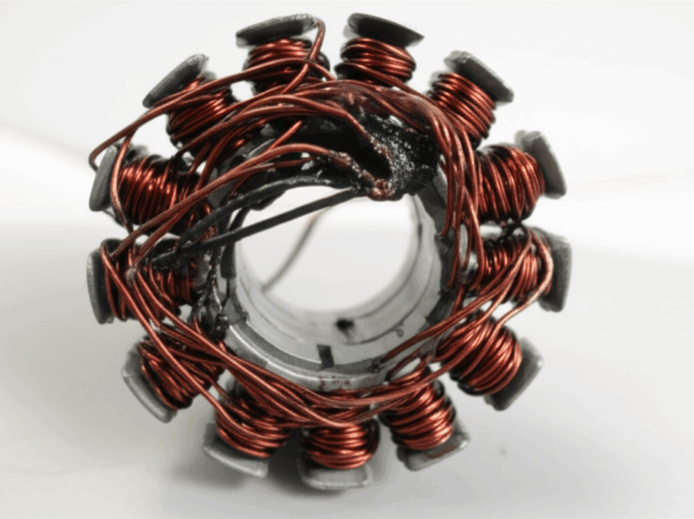
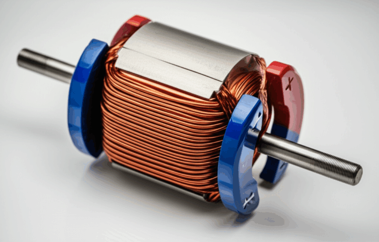
What is a squirrel cage motor and how does it work?
A squirrel cage motor is a type of AC induction motor. It’s tough. It’s simple. It runs fans, pumps, conveyors, and tools. The rotor looks like a cage. The squirrel cage rotor sits inside the stator windings. When you apply voltage, the stator makes a spinning field. That field induces current in the rotor bars. The rotor turns the shaft. You get torque, RPM, and horsepower on demand.
You see two main types in shops. A single-phase motor often has a motor capacitor. It may be a capacitor start motor or a permanent split capacitor motor. A three-phase motor does not use a start cap. It starts smooth. It runs efficient. Both types need the same care. They face the same threats. Heat. Dust. Moisture. Bad power. Poor lubrication. Weak parts.
Is it safe to start? Safety first before any test
Start with Electrical Safety. Use Lockout/Tagout (LOTO). Put on Personal Protective Equipment (PPE). Wear safety glasses and insulated gloves. Follow your Electrical Code (NEC) rules at all times.
Verify the motor is dead before you touch it. Use a meter and test all lines to ground. Check the terminal box. Confirm no live voltage. Respect stored energy. Some caps hold charge. Discharge them with a resistor. Keep one hand in your pocket when you probe live circuits. Do not work alone.
Know the hazards. High volts can kill. Spinning parts can grab you. Hot frames can burn your skin. A short can arc. A fault can trip a circuit breaker or a thermal overload. Play it safe. You have people who count on you.
What tools do you need for motor testing?
You can do a lot with a few tools.
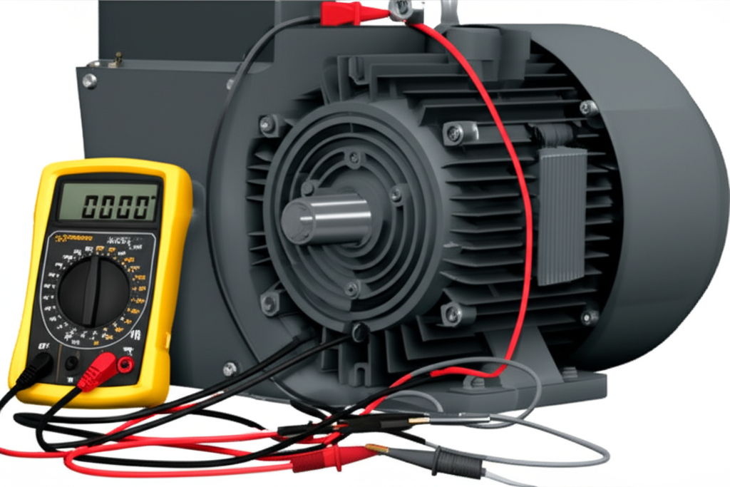
- Multimeter for motor resistance measurement, continuity, and voltage measurement at motor terminals. A Fluke meter works great.
- Megohmmeter (Megger) for insulation resistance. Use 500 V DC for low-voltage motors. Use 1000 V DC for higher voltage. Follow IEEE 43 and NEMA MG1.
- Clamp Meter for current measurement on each phase or line.
- Tachometer to read RPM and slip.
- Infrared Thermometer for thermal checks and hot spots.
- Vibration Analyzer for motor vibration analysis and rotor imbalance detection.
- Growler (test equipment) for growler test rotor bars on small rotors.
- Basic hand tools for the terminal box motor connections.
Here’s a quick tool and test match:
| Test | Tool | What you learn |
|---|---|---|
| Winding resistance | Multimeter (Ohms) | Open circuit or short between windings |
| Continuity | Multimeter (Beep) | Broken wires or connections |
| Ground fault | Multimeter to frame | Short to case or ground fault |
| Insulation resistance | Megohmmeter | Insulation breakdown motor risk |
| Current draw | Clamp meter | Overload or phase imbalance |
| Voltage balance | Multimeter | Voltage drop motor test and power issues |
| RPM | Tachometer | Slip, load, or rotor issues |
| Temperature | IR thermometer | Hot spots and overheating |
| Vibration | Vibration analyzer | Bearing noise motor diagnosis and misalignment |
How do you do a fast visual and sound check?
Start with your eyes. Look for cracks, dents, or corrosion. Check the terminal box for loose, burnt, or frayed wires. Tighten lugs to spec. Inspect the cooling fan and guard. Remove dust and dirt motor accumulation. Clear obstructions. Check the motor mounting integrity. Make sure bolts are tight. Look for oil leaks or grease at the motor bearings.
Spin the shaft by hand. It should turn smooth. No scrape. No bind. Check shaft runout measurement if you see wobble. Look at the coupling. Confirm alignment. Clean the area. Moist places cause moisture ingress motor damage. That leads to low insulation readings.
Now listen and smell with care when you can run it. Use audible motor diagnostics. Hear any grinding, squealing, humming, or clicking. That points to bad bearings, a faulty capacitor, or a weak contactor. Use your nose too. A burning smell means hot insulation resistance is failing. Scan with an infrared thermometer. Hot spots tell a story.
How do you test windings with a multimeter?
Do this with power off. Lock out first.
1) Winding resistance test. On a three-phase motor, measure phase-to-phase: L1-L2, L2-L3, L3-L1. The readings should match. That’s the AC motor winding test values you want. A big difference shows phase unbalance or a stator winding short circuit. On a single phase motor, measure the start and run windings. Compare to the motor nameplate data or service data.
2) Continuity test. Use the beep. Look for an open circuit motor winding. No beep means a break. A very low ohm reading can show a short circuit between turns.
3) Ground fault test. Measure from each winding to the frame. You want a very high ohms value. Near zero means a ground fault. Stop at once if you see that. The motor needs repair.
Keep Ohm’s Law in mind. V = I x R. Low resistance and high voltage make high current. High current makes heat. Heat shortens life.
How do you use a megohmmeter for insulation tests?
A megohmmeter motor testing step checks the health of the insulation. Dry the motor if it was outside or washed. Disconnect the leads from the drive or starter first.
- Set the test level. Use 500 V DC on 230–480 V motors. Use 1000 V DC if the nameplate calls for it. Follow IEEE 43-2000 or the newer edition. Follow NEMA guidance too.
- Test each winding to ground and between windings. Watch the insulation resistance value rise.
- A brand new motor often reads over 100 MΩ. An in-service low-voltage motor should meet the rule of thumb: IR in MΩ ≥ (kV rating + 1). A 460 V motor is 0.46 kV. So 0.46 + 1 = 1.46 MΩ minimum.
Run a Polarization Index (PI) test on larger motors. Read at 1 minute and 10 minutes. PI = IR10 / IR1. A PI above 2.0 is good. New motors often show higher like 4.0. Low PI can mean moisture or dirt. Clean and bake if needed.
Advanced teams may add a motor surge comparison test for turn-to-turn issues. They may run partial discharge motor test on high voltage. They may run eddy current motor testing on rotors. They may check motor core loss testing for the core. Those tests need special gear. Use a pro if you’re not set up.
How do you test the capacitor and the bearings?
Many single phase motor testing jobs end with the cap. A weak start capacitor can make the motor hum. It will not start. A bad run capacitor can make it run hot. It will draw more current. Discharge the cap first with a resistor. Then check the capacitance with your meter. Compare the value to the nameplate μF. Replace if it’s off by more than 5 to 10 percent. Use the right voltage rating.
For testing motor bearings, try three simple checks. First, turn the shaft by hand. Feel for rough spots. Second, listen with a stethoscope or a long screwdriver to your ear. Hear crackle or rumble. That’s a red flag. Third, take temperature monitoring readings while it runs. Rising heat can mean lack of grease or damage. Follow motor re-lubrication frequency rules. Use the right grease. SKF has helpful guides.
Can you test while it runs?
Yes. If it’s safe to run the motor, do in-operation tests.
- Current draw test. Use a clamp meter and check each phase. Compare to the nameplate FLA. A high reading shows overload or a voltage imbalance. A low reading with low torque can show rotor bar issues. You can also apply motor current signature analysis (MCSA) to spot cracked bars or broken end rings.
- Voltage balance test. Measure voltage between phases. Keep the imbalance small. Follow NEMA motor standards testing. A voltage imbalance above 1 percent can cut life. It can raise current and heat. Fix supply issues first.
- RPM measurement. Use a tachometer. Compare to the sync speed by poles and frequency. The difference is slip. Extra slip can show load or rotor imbalance.
- Power checks. If you can, log power factor, current, voltage, and amps trends. Low power factor can point to weak caps or light load.
- Vibration and sound. Use vibration analysis and motor sound analysis. Look for high peaks at bearing or running speed. Balance the rotor. Align the shaft.
On VFD jobs, try variable frequency drive motor testing steps. Check motor current at different speeds. Watch for voltage drop at motor terminals. Verify motor starter troubleshooting is not needed if you use a drive. Drives can hide supply issues.
How do you read results and fix common faults?
Here’s a fast map from symptom to likely fault.
- Open circuit: Motor won’t start or runs weak. You may see one dead phase. The multimeter shows infinite ohms. Fix the open circuit motor winding or the lead.
- Short circuit: The breaker trips. The motor runs hot. The multimeter shows very low ohms. You smell burnt varnish. You need a rewind.
- Ground fault: The megger shows near zero ohms to frame. The circuit breaker or thermal overload trips at once. Pull the motor.
- Bad bearings: You hear grinding or feel roughness. Heat rises. Vibration spikes. Replace bearings. Use correct lubrication.
- Faulty capacitor: A single-phase motor hums but won’t start. Swap in a known good start capacitor or run capacitor. Retest.
- Rotor bar issues: The motor has reduced torque and odd vibrations. Use MCSA or a growler for small rotors. Check rotor bar integrity.
Don’t forget the rest of the circuit. Contactor motor issues can drop a phase. Loose lugs can burn. Motor circuit breaker tripping issues can point to overload. Thermal overload motor protection can save the day. Fix the cause or it will trip again.
When should you call a pro?
Call a motor specialist when you see deep rotor damage, hard stator faults, or need dynamic motor testing you can’t do on site. Bring in help for surge tests, partial discharge, and core loss checks. If you lack the tools or training, call a licensed electrician. Safety comes first. For big jobs, you may work with ABB, Siemens, or General Electric service centers. They know these machines inside and out.
How can smart maintenance cut costs?
I’ve seen predictive maintenance (PdM) save teams real money. Routine preventative maintenance and motor preventative checks can catch most issues. Many studies point to good results. You can see a 25 to 30 percent drop in maintenance costs. You can see a 70 to 75 percent drop in breakdowns. Uptime can rise by 35 to 45 percent. The ROI for PdM can reach 10:1 or even 40:1 in some plants.
Focus on top failure modes. Motor failure analysis shows bearings as the number one cause. They make up about half of motor failures. Stator windings come next. Rotor faults follow. External factors like poor power or bad load also hurt. So you should watch power quality impact on motors. Keep an eye on heat. Clean out dust. Keep water out. Grease on schedule. You’ll sleep better.
Here’s a quick data view you can use:
| Category | Typical value | What it means |
|---|---|---|
| Bearing failures | ~51% | Find early by noise, heat, and vibration |
| Stator winding faults | ~16% | Catch with resistance and megger tests |
| Rotor faults | ~11% | Use MCSA, growler, and vibration |
| External factors | ~10% | Fix power and environment issues |
| Shaft/coupling | ~9% | Check alignment and wear |
| Insulation resistance new | >100 MΩ | New motors should be very high |
| IR in service | ≥ (kV + 1) MΩ | 460 V motor target ≥ 1.46 MΩ |
| PI good | > 2.0 | Low PI points to moisture or dirt |
What inside parts make your motor strong?
The heart of a motor is the core. Strong cores cut heat and waste. They help efficiency testing too. The stator core lamination and the rotor core lamination use thin sheets of electrical steel. Good steel lowers core loss. Good stacks help motor performance evaluation and long life. If you build or rebuild motors, pick high grade laminations. That choice pays off for years.
- Learn how the quality of the stator core lamination affects torque and heat.
- See why a precise rotor core lamination helps with smooth start and steady slip.
- Explore full sets of motor core laminations for new builds or rewinds.
- Understand the impact of premium electrical steel laminations on losses and vibration.
If you spec motors for OEM lines, you know materials matter. Better laminations help NEMA design goals. They support power factor and low heat. They also stand up to stress in industrial motor troubleshooting cases. That’s how you build motors that run cool and last long.
Step-by-step checklist you can print
Use this flow to guide your work. It reads like a motor troubleshooting flowchart in plain words.
1) Safety and setup
- Lock out and tag out
- Wear PPE
- Verify zero voltage at the terminal box
- Read the motor nameplate data for volts, amps, horsepower, and RPM
2) Visual and basic checks
- Check for damage or dirt
- Verify tight terminal box connections
- Inspect cooling fan
- Spin the shaft and check for wobble
- Note smells and hot spots with an IR gun
3) Static electrical tests
- Measure winding resistance on all phases
- Do a continuity test
- Run a ground fault check to frame
- Perform a megohmmeter test for insulation resistance
- If needed run a Polarization Index (PI) test
4) Specific part tests
- Test start and run capacitors
- Check motor bearings for noise and heat
- Inspect the contactor, motor starter, and thermal overload settings
5) Run tests if safe
- Check current on each line with a clamp meter
- Measure voltage balance
- Read RPM with a tachometer
- Log power factor if you can
- Note vibration levels
6) Advanced methods when needed
- Use MCSA for rotor faults
- Try a growler for small rotors
- Consider surge, eddy current, partial discharge, or core loss tests with a pro
7) Decide repair vs replace
- Compare cost and time
- Consider motor repair vs replacement
- Match the fix to the root cause
- Record results for predictive maintenance
Frequently Asked Questions
Q: My motor hums but won’t start. What should I check first
A: Check the capacitor on a single phase unit. Then test winding resistance and look for open circuits. Inspect the contactor and supply voltage too.
Q: How much voltage imbalance is OK
A: Keep it under about 1 percent per NEMA guidance. More can cause heat and early failure.
Q: Can a bad bearing trip my breaker
A: Yes. A tight or seized bearing raises current. Heat rises. The thermal overload can trip.
Q: Do I need a megger for small motors
A: It helps. Even a fractional horsepower motor can fail from wet windings. A megohmmeter spots it fast.
References
- IEEE Std 43: IEEE Recommended Practice for Testing Insulation Resistance of Rotating Machinery
- NEMA MG 1: Motors and Generators
- EPRI and industry studies on AC induction motor failures and PdM results
- NEC: National Electrical Code for electrical safety practices
- SKF Bearing Maintenance Guides
- Fluke Application Notes for motor testing with multimeters, clamp meters, and meggers
- ABB, Siemens, and General Electric motor service literature for advanced diagnostics
Summary
- Lock out first. Wear PPE. Verify no voltage.
- Look and listen. Dirt, heat, and noise tell you a lot.
- Use a multimeter for resistance, continuity, and ground checks.
- Use a megohmmeter for insulation resistance and PI.
- Test caps on single phase units. Check bearings for heat and noise.
- Run tests with a clamp meter, volt readings, RPM, and vibration if safe.
- Watch for phase imbalance, voltage drop, and poor power factor.
- Use MCSA, growler, surge, eddy current, and core tests when needed.
- Fix root causes. Plan predictive maintenance.
- Choose quality cores and laminations for strong builds and long life.
You’ve got this. With a clear plan and the right tests, you can spot the fault, cut downtime, and keep your motors turning day after day.