How to Diagnose and Replace a Bad Stator — and What It Teaches You About Motor Core Laminations
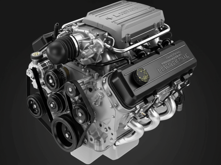
Every engineer faces the same crossroads sooner or later. A fielded product starts killing batteries. Headlights dim at idle. A customer’s ATV dies far from camp on a cold morning. Was it the battery, the regulator/rectifier, or the stator? More importantly, what does this failure say about your lamination material, stack construction, and thermal design choices?
If you’re weighing performance, durability, and cost for stator laminations in motorcycles, ATVs, marine engines, BLDC motors, or small engines, you’re in the right place. I’ll show you how to confirm stator failure with a multimeter, how to replace it safely, and then zoom out to the engineering fundamentals that determine whether your next stator lasts 5,000 miles or 50,000. We’ll connect field diagnostics to lamination physics, material selection, and manufacturing processes so you can design and source with confidence.
In plain English. With practical steps. Backed by sound engineering.
In This Article
- Understanding Your Charging System and the Stator’s Role
- What’s Really Going On Inside the Core: Laminations and Losses
- Symptoms of a Bad Stator: Is Your Stator the Problem?
- Tools and Materials You’ll Need
- Step-by-Step Stator Testing and Diagnosis
- Stator Replacement: A Detailed Guide
- Material Considerations for Stator Core Laminations
- Manufacturing and Assembly Processes That Matter
- Which Application Is This For? Best-Fit Guidance
- Maintenance Tips to Prolong Stator Life
- When to Seek Professional Help
- Data and Practical Insights on Stator Failure
- Procurement Checklist and Next Steps
- Your Engineering Takeaway
Understanding Your Charging System and the Stator’s Role
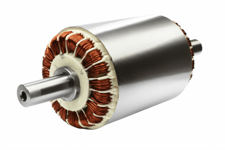
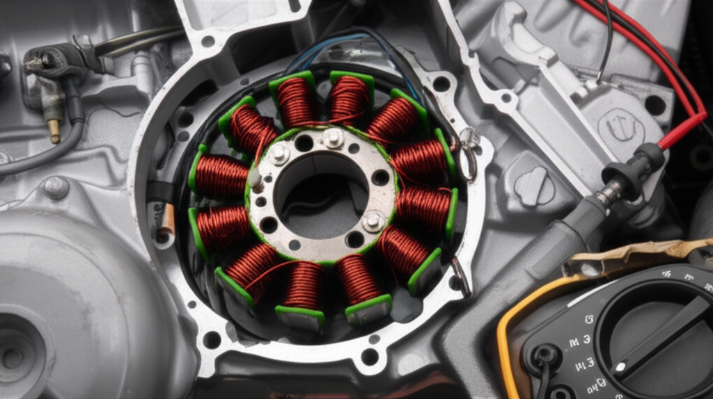
Let’s level-set. The stator is the stationary core with copper windings that, together with a rotating magnetic field (from a rotor with permanent magnets or a field coil), generates AC voltage. In most motorcycles and many small engines, you’re dealing with a permanent magnet alternator. The rotor carries magnets. The stator carries laminated cores and windings. The regulator/rectifier converts the stator’s AC output to DC and holds the battery in a tight voltage window.
Alternator vs stator? An “alternator” is the generator assembly. The stator is the stationary part of that alternator. When you see battery not charging, dim headlights, or a battery that keeps dying, the stator often sits in the suspect lineup with the battery and regulator/rectifier.
A healthy stator matters because:
- It keeps the battery charged at idle and across the rev range.
- It powers lights, ECUs, ignition systems, and accessories.
- It avoids waste heat that cooks insulation, breaks down varnish, and shortens service life.
Common causes of stator failure include overheating from high current draw, a failing regulator/rectifier that overcharges, shorted stator coils from insulation breakdown, oil contamination on models where the stator runs in oil, or physical damage from rotor contact. You may also see corroded connections and melted wiring due to poor connectors or a worn harness.
What’s Really Going On Inside the Core: Laminations and Losses
Why do engineers obsess over lamination materials and thickness? Because electromagnetic losses live there. Two main culprits steal efficiency and create heat:
- Eddy current loss: Changing magnetic fields induce circulating currents in the core. Think of eddy currents like unwanted whirlpools in a river. Thicker, continuous metal creates large whirlpools. Thin, insulated laminations break them up into tiny swirls that dissipate less energy.
- Hysteresis loss: Magnetizing and demagnetizing the core each cycle wastes energy based on the material’s B-H curve. Materials with lower coercivity and optimized chemistry reduce this loss.
The stakes rise with frequency. Higher RPM means higher fundamental electrical frequency in the stator. That increases eddy currents. Thinner laminations (for example 0.35 mm, 0.27 mm, 0.2 mm) and better insulation coatings reduce eddy current loss. The right silicon steel grade and processing lower hysteresis. Get both right and you cool the stator down, raise efficiency, and extend life.
A few quick definitions to keep everyone on the same page:
- Magnetic permeability: How easily magnetic flux passes through a material. Picture how a sponge pulls in water. High permeability materials “soak up” magnetic field lines.
- Coercivity: A material’s resistance to demagnetization. Lower coercivity generally means lower hysteresis loss.
- Core loss: Combined eddy current and hysteresis losses, usually expressed in W/kg at a specific flux density and frequency.
For testing and specification, you’ll see standards like IEC 60404 and ASTM A343 for core loss characterization, ASTM A976 for classification of electrical steels, and ASTM A677 for nonoriented electrical steel. You don’t need to memorize those. You do want your supplier to qualify material against them.
Symptoms of a Bad Stator: Is Your Stator the Problem?
Here’s how stator failure symptoms show up in the real world:
- Battery-related issues
- No charge to battery. The battery keeps dying after short rides.
- Dim headlights or dashboard lights, especially at idle.
- Engine won’t start or struggles to crank. Sometimes it starts then quickly stalls.
- Performance-related issues
- Engine misfires or rough running if ignition or ECU voltage sags.
- Burning smell from the engine area if windings overheat.
- Visual cues
- Melted wiring, corroded connections, or discolored wires near the stator.
- Burnt stator windings visible upon inspection after removing the cover.
These aren’t unique to motorcycles. ATVs, snowmobiles, and marine engines show the same signals. A “battery drain problem” gets blamed first. Many times the charging system sits at fault. That includes the regulator/rectifier and the stator. Misdiagnosis happens because all three components are interconnected.
Tools and Materials You’ll Need
You don’t need a laboratory. You need a handful of standard tools and basic PPE.
Essential tools:
- Multimeter with AC voltage, DC voltage, and Ohm settings
- Voltmeter functions or a separate voltmeter for convenience
- Socket set and screwdrivers
- Pliers (needle-nose and side cutters)
- Torque wrench
- Flywheel puller tool specific to your make and model
- Oil drain pan and fresh engine oil if the stator lives under the left cover in an oil bath
- Shop rags or clean towels
- Battery charger for a controlled battery baseline
Replacement parts and consumables:
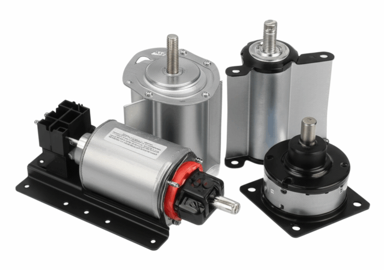
- New stator (OEM or reputable aftermarket)
- Stator cover gasket
- Dielectric grease for connectors
- Threadlocker (Loctite blue) for fasteners
- Heat-resistant wiring and proper electrical connector seals if you find damage
Keep the service manual open for torque specs, wiring diagram, and the stator test values. Different brands like Honda, Yamaha, Suzuki, Kawasaki, Ducati, Harley-Davidson, Polaris, and Can-Am publish their specific ranges and procedures. Follow those numbers. They’re your guardrails.
Step-by-Step Stator Testing and Diagnosis
You want to test in a logical order. Confirm the battery is good. Inspect the regulator/rectifier. Then test the stator.
A. Pre-test checks
- Fully charge the battery. Verify open-circuit voltage around 12.6 V or higher for a healthy 12V lead-acid battery. If it sits well below this after charging, replace it before you chase ghosts.
- Quick regulator/rectifier check
- Inspect for burnt wiring or melted connectors.
- Many units allow a simple diode or continuity check across terminals. Your service manual shows the correct polarity checks.
- A regulator/rectifier that overcharges often kills stators through overheating.
B. Visual inspection
- If accessible, pull the stator cover to inspect windings. Look for burnt, melted, or discolored stator windings. Confirm that epoxy potting around coils hasn’t cracked or lifted. Check the wiring harness and connector seals.
C. Multimeter tests
1) Resistance test (Ohms test)
- Disconnect the stator from the regulator/rectifier to isolate it.
- Set the multimeter to the lowest Ohm range.
- For a three-phase stator, test between each pair of the three output wires:
- A to B, B to C, and A to C.
- Typical readings fall between about 0.1 Ω and 1.0 Ω. Your service manual wins if it says otherwise.
- Look for consistency. If two pairs read 0.5 Ω and the third reads OL (open circuit), you likely have an open circuit stator winding. If a pair reads near 0 Ω and the others don’t, you may have shorted stator coils.
2) Ground fault test
- Test resistance from each stator output wire to ground (engine case).
- You should see OL (no continuity) in a healthy stator. Any measurable continuity to ground indicates insulation breakdown and a short to ground.
3) AC output voltage test (running engine)
- Reconnect the stator to the harness if required by your manual. Many procedures test the stator disconnected from the regulator/rectifier.
- Start the engine with a charged battery. Set your meter to AC volts.
- Test AC voltage between each pair of stator wires at idle and again at 3,000–5,000 RPM.
- Expect roughly 20–70+ VAC depending on RPM and model. All three phases should be close in value. Low or no voltage on a phase points to a failed winding or rotor magnet issue.
4) DC charging test (system-level validation)
- With the system connected, check battery voltage at idle and then at 3,000–5,000 RPM.
- You want about 13.5–14.8 V DC at the battery at cruise RPM. Lower suggests undercharging. Higher suggests regulator failure or miswiring.
These tests take 15–30 minutes. They remove guesswork. They also tell you whether you’ve got a stator problem, a regulator/rectifier problem, or a wiring harness issue.
Stator Replacement: A Detailed Guide
If your tests confirm “how to check if stator is bad” with certainty, replacement isn’t complicated. It does require patience and the right tools.
A. Preparation and safety
- Disconnect the battery negative terminal.
- Drain engine oil if the stator sits behind an oil-immersed cover.
- Set the bike or engine securely on a stand. Clean the area so debris won’t fall inside.
B. Removing the old stator
- Remove the side engine cover (stator cover). Catch any oil with the drain pan.
- Disconnect the stator wires from the main harness. Label them if needed. Document routing and clamps with a quick photo.
- Use the correct flywheel puller to remove the flywheel. Your service manual will specify thread size and procedure. Don’t hammer on it. You’ll damage the crank.
- Remove stator mounting bolts. Capture any spacers or unique hardware. Remove the stator assembly.
C. Installing the new stator
- Clean the mounting surface. Remove gasket residue and old sealant without gouging the surface.
- Route the new stator wires as designed. Keep them clear of rotating parts. Replace grommets and use stator sealant only where the manual allows it.
- Apply threadlocker to stator mounting bolts. Torque to spec.
- Reinstall the flywheel. Align the keyway. Torque the crank nut to spec with a torque wrench.
- Install a new stator cover gasket and the cover. Torque cover bolts in a cross pattern to avoid leaks.
- Reconnect stator wires to the harness. Use dielectric grease on connectors to prevent corrosion.
D. Post-install checks
- Refill engine oil if drained.
- Reconnect the battery.
- Start the engine and repeat the AC output test at the stator leads. Confirm phase-to-phase AC outputs match spec.
- Measure DC voltage at the battery at idle and at 3,000–5,000 RPM. Confirm proper charging.
A note on parts: OEM vs aftermarket stator options vary in quality. Reputable aftermarket stators often use improved winding insulation and better epoxy potting. Cheap options can save dollars up front. They can cost you in callbacks and downtime. Match the stator’s quality to the application’s duty cycle and thermal environment.
Material Considerations for Stator Core Laminations
Now let’s connect the field failure to what you design and buy. Core material and thickness drive the heat you fight and the efficiency you deliver. Your choice also sets the tone for cost, availability, and manufacturability.
- Nonoriented electrical steels (NOES, M-grades)
- Use: General-purpose motors, motorcycles, ATVs, small engines, BLDC stator cores.
- Pros: Widely available, cost-effective, consistent properties in all in-plane directions. Mature design data.
- Cons: Higher loss than specialty alloys at very high frequencies or flux densities.
- Typical thickness: 0.5 mm, 0.35 mm, 0.27 mm, 0.2 mm. Thinner reduces eddy currents at higher electrical frequency.
- Silicon steel laminations
- Silicon additions reduce core loss and improve resistivity. The right coating between laminations improves interlaminar resistance and reduces shorting between plates.
- Grain-oriented steels (CRGO)
- Use: Transformers and devices with predominantly unidirectional flux. Less common for rotating machines that see rotating flux.
- Cobalt-iron alloys
- Use: High-power-density motors, aerospace, and machines that push flux density hard.
- Pros: High saturation flux density, excellent performance in aggressive designs.
- Cons: High cost. Machining, stamping, and heat treatment require care.
- Emerging and special materials
- Amorphous steels and nanocrystalline materials shine in transformers and certain high-frequency machines. They can be tricky to process in traditional motor topologies.
Ask for core loss data at the operating point that matters. For example, 50 Hz test data at 1.5 T tells you something. It may not tell you enough for a motorcycle stator running at several hundred Hz fundamental. Suppliers can provide Epstein test data per IEC 60404 or ASTM A343 at multiple frequencies and flux densities.
For a deeper dive on common grades and use cases, see this overview of electrical steel laminations. If you’re specifying entire lamination stacks for a program, you can also align to proven configurations across a portfolio. That reduces qualification risk.
Manufacturing and Assembly Processes That Matter
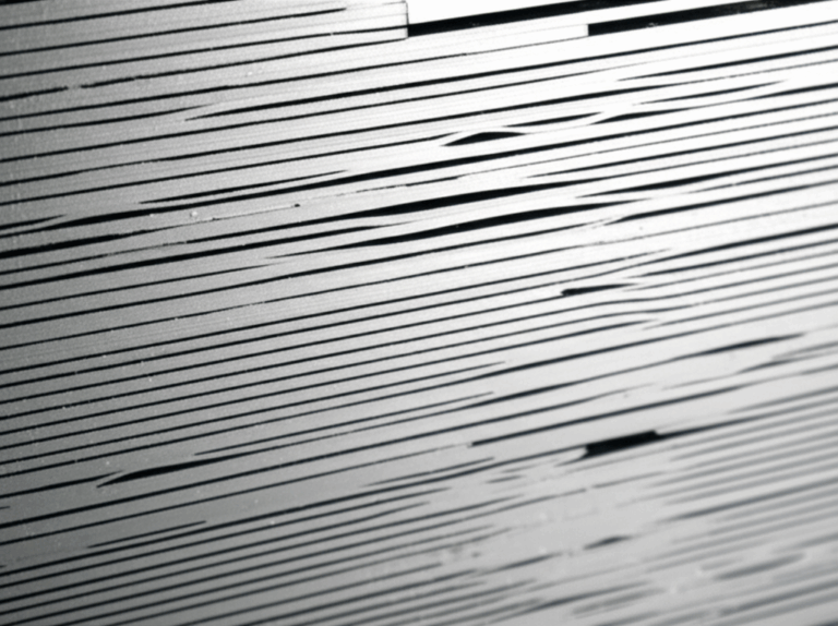
The way you cut, stack, and assemble the laminations changes the electrical and mechanical performance. It also affects yield and cost.
Cutting
- Progressive die stamping
- Best for high-volume production. Excellent repeatability, lowest cost per part once tooling is amortized.
- Watch out for burrs. Burr height increases interlaminar shorts and core loss. Specify maximum burr height and include a deburr process if needed.
- Laser cutting or wire EDM
- Ideal for prototypes, quick turns, complex geometries, and low-volume builds.
- Clean edges with minimal burr. Heat-affected zone from laser cutting can slightly increase loss in some steels. Post-cut annealing can recover properties if required by the design.
- Waterjet
- No heat-affected zone. Slower with thicker stacks. Tolerance and kerf can limit very fine details.
Stacking and bonding
- Interlocking laminations
- Think LEGO bricks. Tabs lock the stack mechanically. No adhesives. No weld heat.
- Fast and robust for many assemblies.
- Adhesive bonding
- Structural bonding creates a rigid, quiet core with uniform stress distribution. Great for NVH, especially in BLDC and PMAC machines.
- Requires process control and qualified adhesives. Post-bond cure schedules matter.
- Welding or riveting
- Strong and simple. Local heat can alter magnetic properties near welds. Use minimal welds outside high flux regions when possible.
Insulation and coatings
- Interlaminar coatings raise resistivity between plates. They cut eddy current loops and lower loss.
- Slot liners and winding insulation ratings must match expected heat. High-temperature varnishes and epoxy potting around windings improve thermal conductivity and protect against vibration.
Post-process heat treatment
- Annealing after cutting relaxes stress and restores magnetic properties in many grades.
- Not every design needs it. Complex programs should qualify the effect through core loss testing before and after annealing.
You can build exceptional machines with any of these paths if you match the process to volume, geometry, and performance targets. If you’re benchmarking options for an upcoming program, review your volume estimates and tolerance stack early. That decision pays dividends for years.
Which Application Is This For? Best-Fit Guidance
One size never fits all. Anchor your decisions to your application’s duty cycle and environment.
- Motorcycles and dirt bikes
- High vibration and heat cycles. Oil-cooled stators help. Use mid to low-loss NOES with robust insulation coatings. Design for easy service because riders put miles on these systems.
- Consider the regulator/rectifier’s thermal path. Overcharging kills stators faster than poor material does.
- ATVs and side-by-sides
- Mud, water crossings, and slow crawling with heavy electrical loads. Favor higher-grade insulation and sealed connectors. Check wire routing and strain relief.
- Marine engines
- Salt fog and splash demand aggressive corrosion protection. Potting compounds and dielectric grease on connectors help.
- Snowmobiles
- Low ambient temperatures but heavy load at high RPM. Make sure lamination thickness matches frequency. Verify potting and adhesives perform in the cold.
- BLDC motors for e-bikes, tools, or industrial drives
- Higher electrical frequency in compact stators. Thinner laminations and precise bonding often pay off. Rotor magnets and rotor core laminations should match the stator in quality to keep balance and performance tight.
If you’re working on a permanent magnet machine, balance rotor and stator choices. Stator geometry and lamination stack quality set the stage for efficiency. Rotor metallurgy, magnet grade, and rotor core lamination quality complete the picture.
For a quick overview of complete assemblies, this guide to motor core laminations outlines common stacks and integration paths. If you’re deep into stator design, you can zero in on stator core lamination options for different topologies.
Maintenance Tips to Prolong Stator Life
Design sets the ceiling on life. Maintenance fills the gap between “should” and “did.”
- Change oil on schedule if the stator runs in oil. Contaminants and degraded oil reduce cooling.
- Keep connectors clean. Use dielectric grease. Corroded connections create heat and voltage drop.
- Avoid overloading the electrical system with high-draw accessories. Check the charging system diagram and confirm current draw fits the regulator’s envelope.
- Inspect the wiring harness for chafing and melted wiring at service intervals.
- Confirm regulator/rectifier cooling airflow. Heat sinks need a path to shed heat.
Small habits protect big investments. They also keep customers out of roadside trouble.
When to Seek Professional Help
DIY can handle diagnosis and many replacements. Call in a pro if:
- You don’t have a flywheel puller or specialty tools. Improvised tools damage cranks and cases.
- You feel unsure about the diagnosis. A professional stator repair or electrical system diagnosis can save days of frustration.
- You find complex wiring issues or intermittent faults.
- Time pressures outweigh the cost of labor.
Professional repair often runs $300–$800+ depending on labor rates and parts. DIY parts typically range from $80–$300 for aftermarket or $200–$600+ for OEM. That spread pushes many riders to DIY if they have the tools and patience.
Data and Practical Insights on Stator Failure
The exact failure rates vary by platform and environment. Trends repeat across brands and use cases. Here’s a concise summary that aligns with mechanic experience and industry observations.
| Category / Metric | Description and Data Points | Source / Context |
|---|---|---|
| Typical Lifespan | 5–10 years or 20,000–50,000+ miles for motorcycles and ATVs under typical use. High heat and vibration shorten life. | Mechanic consensus and market experience |
| Common Causes (Motorcycles) | Overheating drives 60–70% of failures. Insulation breakdown 20–30%. Physical damage 5–10%. | Service experience and aftermarket supplier notes |
| Failure Impact | Stators rank as a leading cause of roadside breakdowns after batteries. Many “battery issues” trace back to the charging system. | Rider forums and roadside data summaries |
| DIY vs Professional Cost | DIY parts: $80–$300 aftermarket, $200–$600+ OEM. Shop repair: $300–$800+ with labor. | Typical parts pricing and shop rates |
| Misdiagnosis Rate | 30–40% of “battery” or “regulator/rectifier” complaints eventually trace back to a failing stator. | Troubleshooting patterns in shops |
| Reg/Rec Impact | Overcharging from a failing regulator/rectifier can drastically shorten stator life. | Manufacturer advisories and diagnostics guides |
| Aftermarket Quality | Many reputable aftermarket stators use improved epoxy and winding insulation. Quality varies by brand. | Product literature and reviews |
| DIY Time | 1–3 hours for experienced techs. 3–6+ hours for novices. | Shop and DIY experience |
Note: Always verify stator test values, resistance range, AC output test results, and torque specs in your service manual. Data above is general, not a substitute for model-specific documentation.
Procurement Checklist and Next Steps
You’re not just fixing a stator. You’re improving your product. Here’s how to translate field findings into better specs and sourcing decisions.
Material and design requirements
- Target electrical frequency range and RPM envelope. Select lamination thickness accordingly.
- Specify core loss at operating point (W/kg at specific B and frequency). Ask for Epstein test data per IEC 60404 or ASTM A343.
- Define permissible burr height and edge quality. Include deburring or post-cut anneal as needed.
- Confirm interlaminar coating type, thickness, and resistivity. Require consistency certificates.
Manufacturing and QA
- Choose cutting process matched to volume and tolerance needs: progressive die stamping for volume, laser or EDM for prototypes and complex low-volume.
- Define stacking method: interlock, adhesive bonding, or weld. Specify location and limits for welds if used.
- Require stack height tolerance, slot geometry tolerance, and concentricity to fit your winding process and rotor.
- Include magnetic and dimensional inspection checkpoints. Lock down gauge plans for in-process and final inspection.
Winding and assembly
- Set winding insulation class and varnish or epoxy potting requirements. Validate thermal paths with your heat cycle.
- Specify connector type, seal class, and dielectric grease use. Provide harness strain relief details.
- Document torque specs for all fasteners. Include threadlocker types where used.
System-level considerations
- Confirm regulator/rectifier thermal management. Make sure airflow or heat sinking meets worst-case load.
- Provide a charging system diagram for service and troubleshooting. Train dealers to perform basic multimeter stator tests.
Sourcing and collaboration
- Ask for material certifications and batch-level traceability.
- Request trial builds with core loss testing before and after cutting or annealing.
- Share your operating profile. Your supplier can suggest alternatives if your duty cycle pushes the envelope.
If you want a concise overview and options for full assemblies, this high-level look at motor core laminations helps frame supplier discussions. For stator-specific stacks and topologies, review stator core lamination. To round out rotor discussions and magnet support, see rotor core lamination.
Your Engineering Takeaway
Let’s bring it home.
- Diagnose before you replace. A simple multimeter stator test saves hours and money. Run the resistance test, the ground test, and the AC voltage test.
- Fix the root cause, not just the symptom. Verify the regulator/rectifier and wiring harness. Overcharging or corroded connectors can cook a new stator fast.
- Lamination choices drive heat and efficiency. Thinner, well-insulated laminations cut eddy current loss at higher electrical frequencies. Smarter material selection and coatings reduce hysteresis loss and keep windings cooler.
- Manufacturing details matter. Burr control, insulation coatings, bonding, and post-cut anneal can swing core loss numbers and long-term stability.
- Match the solution to the application. A rugged ATV doesn’t want the same stackup as a high-frequency BLDC in an e-bike. Different jobs need different tools.
- Document and communicate. Clear specs, test methods, and acceptance criteria make procurement smoother and outcomes predictable.
Ready for next steps? Pull your last failure report. Map the symptoms to the tests above. Capture your operating frequency and flux targets. Then share that package with your lamination supplier for a technical review. A short, focused conversation now can save months of redesign and thousands of field dollars later.
Appendix: Practical Testing Quick-Reference
- Resistance test (ohms test stator): 0.1–1.0 Ω typical phase-to-phase, consistent across pairs.
- Ground test stator: OL from each stator lead to ground. Any continuity means a short.
- AC voltage test stator: 20–70+ VAC phase-to-phase depending on RPM and model. All phases should match closely.
- DC charging check: 13.5–14.8 V DC at the battery at 3,000–5,000 RPM.
Symptoms of an undercharging system include dim headlights, a battery that keeps dying, and difficult starts. Symptoms of an overcharging system include blown bulbs, hot smells, and high battery voltages that climb past 15 V. Either condition shortens stator life.
If you’re designing the next generation machine, remember the big picture. Better laminations mean lower core loss. Lower core loss reduces winding temperature. That protects insulation, prevents shorted stator coils, and keeps the charging system happy. Your users won’t notice the stator. They’ll just ride.