How to Check a 3-Phase Motor: My Step‑by‑Step Playbook for Fast, Accurate Diagnostics
Table of contents
- Introduction: Why I Check Every 3-Phase Motor the Same Way
- Safety First: The Pre-Inspection Protocols I Never Skip
- The Essential Tools I Carry for 3-Phase Motor Diagnostics
- Step-by-Step Procedures You Can Follow
- Visual Inspection: External and Internal Checks
- Electrical Tests With Power Off
- Winding resistance test (phase-to-phase and phase-to-ground)
- Insulation resistance test with a megohmmeter (DAR and PI)
- Continuity and DC resistance checks
- Live Electrical Tests With Power On
- Voltage measurement and unbalance
- Current draw with a clamp meter and FLA comparison
- Temperature monitoring and hot spot hunting
- Mechanical Checks That Save Motors
- Bearings, vibration, shaft rotation, and alignment
- Interpreting Results: What the Readings Tell Me
- Common 3-Phase Motor Problems and How I Solve Them
- When I Call a Professional or Replace the Motor
- Preventative Maintenance That Actually Extends Motor Life
- Final Thoughts: Proactive Checks Pay for Themselves
Introduction: Why I Check Every 3-Phase Motor the Same Way
I learned the hard way that a 10-minute check can save a 10-hour outage. Early in my career I rushed to restart a tripped 3-phase induction motor. The line was down. Production was screaming. I reset the breaker and the motor came back hot and noisy. Fifteen minutes later it tripped again and it smelled like burned varnish. My gut sank. I skipped the basics. Lesson burned in.
Since then I’ve used a simple playbook any time I check a 3-phase motor. It works on AC induction motors in plants, workshops, and field sites. It covers the essentials: electrical tests, mechanical checks, and power quality. It uses common tools like a multimeter, a clamp meter, a megohmmeter, and an infrared thermometer. When available I add predictive tools like a vibration analyzer or an infrared camera. You can follow the same flow and you’ll catch most faults before they get expensive.
This guide walks you step by step. I’ll show you how to test windings, insulation, voltage balance, current draw, and temperature. I’ll point out common causes like single phasing, loose connections, rotor bar issues, bad bearings, and cooling problems. I’ll share numbers I use from industry standards like NEMA and IEEE. I’ll also show you when to stop and call in a motor technician.
Safety First: The Pre-Inspection Protocols I Never Skip
I don’t touch a motor until I handle safety. These are non-negotiable.
- Lockout/Tagout (LOTO): I follow facility procedures and verify all energy sources are isolated. I lock it. I tag it.
- PPE: I wear arc-rated PPE appropriate for the task, safety glasses, insulated gloves, and hearing protection if needed. OSHA sets the tone on this. Stay on the safe side.
- Verify zero energy: I try to start the motor from the control panel to verify it cannot start. I test with a meter for residual voltage. I discharge stored energy in VFDs per the manufacturer’s instructions.
- Work area: I clear debris. I ensure dry footing. I keep bystanders out of the arc flash boundary during energized testing.
You only get one body. Respect it.
The Essential Tools I Carry for 3-Phase Motor Diagnostics
I keep my kit tight and effective.
- Multimeter: True RMS for voltage and resistance. I use it for terminal checks, phase-to-phase resistance, and basic continuity.
- Clamp meter: For current draw on each phase. I match measured amperage against the nameplate Full Load Amps (FLA) and the overload relay settings.
- Megohmmeter (Megger): For insulation resistance. I test winding-to-ground and winding-to-winding. I also record DAR and PI when it matters.
- Infrared thermometer or camera: I scan bearings, casing, terminal box, and power cables for hot spots.
- Optional gear: Vibration analyzer, power analyzer, growler for rotor bar checks, and a surge tester for deeper winding diagnostics. A growler is old-school yet still useful on certain rotor checks.
I also bring spare lugs, ferrules, a torque wrench for terminals, alignment tools, and a small mirror for tight spaces.
Step-by-Step Procedures You Can Follow
I run my checks in this order. It keeps me from missing something simple.
Visual Inspection: External and Internal Checks
Start with your eyes and ears. Many failures announce themselves.
- Exterior condition: I look for physical damage on the casing, feet, cooling fan, and shaft. A cracked cooling fan or bent guard hurts airflow. Dust and debris accumulation choke cooling fins and vents. I’ve seen a motor run hot from a single rag stuck in the fan shroud.
- Terminal box and junction box: I open it up. I inspect for corrosion on terminals, loose connections, overheated insulation, and signs of arcing. I check for moisture ingress or condensation. I pull gently on conductors and confirm torques if I have the specs.
- Nameplate data: I note voltage, frequency, connection type (wye or delta), service factor, IP rating, duty cycle, and FLA. These numbers drive your pass/fail decisions. I match the nameplate RPM against expected mechanical speed later.
- Conduit and wiring: I look for damaged insulation, poorly supported conduit, and missing grommets. I check the motor control circuit and the condition of overload relays, contactors, and the circuit breaker or fuses.
- Environment: I note ambient temperature and dust load. I look for oil, water, or chemicals nearby. Harsh environments drive up maintenance needs.
- Mounting and alignment: I scan the base and feet for cracks or shims that shifted. Loose mounting leads to vibration and bearing wear.
Electrical Tests With Power Off
Once LOTO is in place and I’ve verified zero energy I dig into the windings.
Winding resistance test (Ohmmeter)
- Phase-to-phase resistance: I label phases R, S, T. I measure R-S, S-T, and T-R at the motor terminals. The three readings should be closely matched. I like them within 2 to 5 percent on small to mid-size motors. A large mismatch hints at a bad connection, a shorted turn, or a partial open.
- Phase-to-ground resistance: I switch to a higher range if needed and check each phase to the motor frame. In a basic ohmmeter test I want an open circuit. If I see any measurable ohms the insulation likely has a problem.
- Interpreting results: A much higher resistance on one phase means an open or a bad lead. A much lower resistance on one phase suggests a short or inter-turn issues. If all three are high or all three are low I look for a misconnection in the terminal box or a star/delta miswire.
Insulation resistance test (Megohmmeter/Megger)
This is one of the most valuable tests I run.
- Winding-to-ground: I connect all three phase leads together and test to the grounded frame. I select a test voltage per IEEE 43 guidance. For low-voltage motors I often use 500 VDC or 1000 VDC. I hold for 60 seconds and record the final megohm value.
- Winding-to-winding: I test between phases as well. This catches insulation weakness between coils or phases.
- Minimum acceptable values: A common rule of thumb is 1 megohm per kV of rated voltage plus 1 megohm. More is better. New or freshly baked motors often measure in the hundreds of megohms or higher. I care most about trends over time.
- DAR and PI: I use Dielectric Absorption Ratio and Polarization Index when I need a deeper read on insulation health. DAR is the 60-second reading divided by the 30-second reading. PI is the 10-minute reading divided by the 1-minute reading. Healthy insulation shows a rising resistance as the test progresses. A PI below about 2 can flag moisture, contamination, or aging for many insulation classes. I always check the motor class and manufacturer guidance since Class F or H may behave differently.
Continuity and DC resistance checks
- Continuity: I confirm each winding path is continuous. I verify coil groups if the motor is reconfigurable between wye and delta.
- DC resistance: I sometimes record absolute DC resistance per phase to build a baseline for trending temperature-corrected values. Not essential for a quick check yet useful for predictive maintenance.
Live Electrical Tests With Power On
I only energize for these tests when it is safe to do so and when I can keep hands off conductors. I set up test points before I re-energize.
Voltage measurement and unbalance
- Line voltage: I measure R-S, S-T, and T-R with a true RMS multimeter. I compare against the nameplate phase voltage and line voltage for the connection type.
- Unbalance: I compute percent voltage unbalance using the NEMA method. Find the average of the three phase-to-phase voltages. Find the maximum deviation from that average. Percent unbalance equals (max deviation / average) x 100. NEMA MG 1 warns that even small unbalance can cause large current unbalance. I try to keep voltage unbalance at or below 1 percent. Above that I start to derate or I fix the supply.
- Effects: A 3.5 percent voltage imbalance can increase winding temperatures by roughly 25 percent. Heat kills insulation life faster than almost anything.
Current draw with a clamp meter and FLA comparison
- Measure each phase: I clamp R, S, and T. I compare the numbers to each other and to the nameplate FLA. I check the overload relay setting too.
- Unbalance and overload: Current unbalance should be minimal. If current unbalance is six to ten times the voltage unbalance I go hunting for a connection issue, a partial open turn, or a single phasing condition.
- Load checks: No-load current should be a modest fraction of FLA on an induction motor. If no-load current is high I suspect a supply issue, rotor problem, misalignment, or an internal fault. If full-load current exceeds FLA consistently I look for mechanical overloading, belt tension problems, or power quality issues like low voltage.
Temperature monitoring and hot spot hunting
- Infrared scan: I measure the surface temperature of the casing, bearing housings, and terminal box. I look for localized hot spots. I compare bearings left to right. A hot bearing relative to the other side hints at lubrication issues or misalignment.
- Nameplate and insulation class: I mind the motor insulation class and service factor. Exceeding rated operating temperature by 10 Celsius can halve insulation life. I do not ignore a motor that always runs “a bit warm”.
Mechanical Checks That Save Motors
You can mask a mechanical problem with electrical band-aids for a while. You will pay later. I always check the basics.
Bearing condition assessment
- Listen and feel: Grinding, squealing, or rumbling noises signal trouble. I use a mechanic’s stethoscope or an ultrasonic probe if available. I touch the housing carefully to feel roughness after I power down.
- Heat and leaks: Bearings that run much hotter than the other side worry me. I look for over-lubrication or under-lubrication. Grease expulsion or contamination shows up as dirt packed with oil near the seals.
- Lubrication: I verify the right grease type and interval. Over-lubrication causes churning and heat. Under-lubrication causes metal-on-metal wear. Contamination ruins bearings quickly.
Vibration analysis and alignment
- Vibration: If I have a vibration analyzer I check spectrum peaks for imbalance, misalignment, looseness, or bearing defects. Vibration analysis can spot bearing wear months before you can hear it.
- Alignment and mounting: I check shaft alignment in coupled systems and belt tension for belt drive systems. I inspect couplings for wear. I confirm the motor mounting integrity and tightness.
Shaft rotation checks
- Free rotation: With power off I spin the shaft by hand. I want smooth rotation. Any notchiness raises a red flag.
- Rotation direction: On first start or after work I jog the motor to verify proper rotation direction. I swap any two phases to reverse rotation if needed.
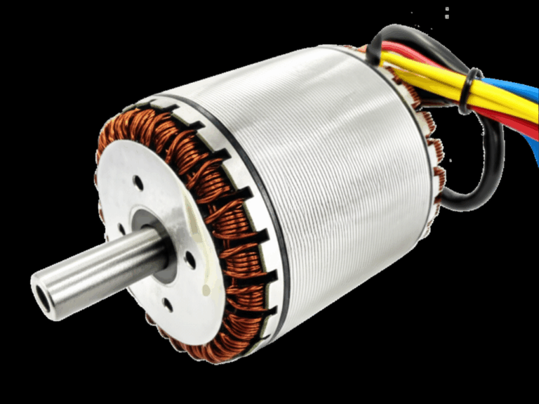
A quick note on motor construction and core losses
Core quality matters. I have chased “mystery heat” that came from poor laminations or damage that increased core losses. If you ever evaluate replacements or rebuilds it pays to understand the impact of laminations and metallurgy. The performance and heat profile depend on the quality of the stator core lamination stack and the rotor core lamination. I have seen real gains from better motor core laminations and modern electrical steel laminations. Better steel and tighter stacks cut core losses so the motor runs cooler at the same load.
Interpreting Results: What the Readings Tell Me
Here is how I read the common tests and what I do next.
- Phase-to-phase resistance
- Close match across all three phases: Good sign. I still compare to historical baseline if I have it.
- One phase way higher: Likely an open winding, a loose crimp, a bad lead, or a broken connection in the terminal box.
- One phase way lower: Possible shorted turns. I verify with a surge test or motor circuit evaluation if available.
- Insulation resistance
- Very high and stable: Healthy. I log it.
- Marginal values near the “1 megohm per kV + 1” rule: I dry out the motor if moisture is suspected. I clean contamination. I retest. If values trend down over time I plan for service.
- PI below about 2 on many motors: Possible aging, contamination, or moisture. I investigate environment and cleaning. I consider a bake and re-varnish if the motor is worth it.
- Voltage unbalance
- Below 1 percent: Ideal. I smile.
- Above 1 percent: I hunt upstream. I check transformer taps, feeder connections, and single-phase loads creating imbalance. I consider a derate if I cannot fix the supply quickly.
- Current draw
- Within FLA and balanced: Good. I verify the overload relay settings and record readings.
- High current with correct voltage: Possible overload, mechanical binding, misalignment, or rotor issues like broken bars. On squirrel cage induction motors broken rotor bars can produce a characteristic current ripple. I investigate with vibration or specialized tests if I suspect rotor bar issues.
- High current on one phase: I look for a loose connection, single phasing, or a contactor issue.
- Temperature
- Even and within expectations: Fine. I still scan next week to confirm.
- Hot spot on the terminal box: Loose or corroded connections. I clean, re-terminate, torque, and recheck.
- Hot bearing: Lubrication or alignment problem. I fix it before it turns into a seized bearing and a burned stator.
Common 3-Phase Motor Problems and How I Solve Them
Single phasing
- Symptoms: The motor hums. It struggles to start. It draws high current on remaining phases. It overheats fast. Protection trips if it works.
- Causes: Blown fuse, failed contact in the contactor, loose terminal, broken conductor, or a control circuit fault.
- Fix: Find and correct the open phase. Verify overload relay settings. Consider phase loss protection.
Winding faults: opens, shorts, and ground faults
- Symptoms: Imbalanced resistance readings. Tripping on start. Burning smell. Visible coil discoloration.
- Tests: Winding resistance, megger to ground, surge test for inter-turn shorts, and a growler or motor circuit analyzer for deeper diagnostics.
- Fix: Rewind or replace. I consider cost, size, and downtime before I choose.
Bearing failure
- Symptoms: Noise, heat, vibration, or shaft play. Sometimes it starts subtle. Vibration analysis can catch it early.
- Root causes: Lubrication issues, contamination, misalignment, or electrical discharge through bearings on VFD drives.
- Fix: Correct lubrication. Improve seals. Install insulated bearings or shaft grounding brushes when VFDs cause fluting. Align the machine. Replace bearings before they damage the stator and rotor.
Overheating
- Symptoms: Motor runs hot to the touch. Paint discoloration. Thermal protection trips. Reduced insulation resistance over time.
- Causes: Blocked cooling fins or vents, failed cooling fan, excessive load, voltage imbalance, harmonics from a VFD with poor filtering, high ambient temperature, or poor mounting that traps heat.
- Fix: Clean the motor. Restore airflow. Correct the electrical supply. Adjust the load or upgrade the motor. Verify service factor and duty cycle.
Power supply issues
- Voltage drop: Long cable runs or undersized conductors drop voltage under load. I calculate voltage drop and confirm with a power analyzer. I upsize conductors or shorten runs if possible.
- Harmonics and power factor: Harmonic distortion from non-linear loads affects heating. Poor power factor wastes capacity. I check with a power quality analyzer and apply fixes like filters or power factor correction as needed.
- Protection sizing: I verify circuit breaker and fuse ratings match the motor’s needs and the starting method. Wrong sizing leads to nuisance trips or inadequate protection.
VFD-specific checks
- Output checks: I verify the VFD output matches motor ratings and the application. I confirm carrier frequency and acceleration ramps fit the load. I scan for excessive cable length or lack of proper grounding that increases common-mode voltage.
- Motor insulation: VFDs stress insulation more due to fast switching. I use motors rated for VFD duty when the application demands it. I add dV/dt filters when necessary.
Real-life examples that taught me fast
- The loose lug: A 75 kW motor ran “hot” with current unbalance over 10 percent. Voltage unbalance measured 0.7 percent. The fix was a single loose lug in the terminal box. I tightened and rechecked. Current balanced and temperature dropped within minutes.
- The blocked fins: A blower motor tripped every afternoon. IR scan showed a hot casing and hotter non-drive bearing. The cooling fins were packed with flour dust. A careful cleaning cut case temperature by 20 Celsius. No more trips.
- The damp storage rewind: A spare motor came out of storage with low insulation resistance. We baked it per vendor guidance and repeated the megger test. IR rose above 200 megohms and the PI improved. We installed it without issues.
When I Call a Professional or Replace the Motor
I love solving problems in-house. I also know when the clock is ticking and the risk is high.
- Complex diagnostics: Surge testing, detailed motor circuit analysis, rotor bar tests on large machines, and advanced vibration diagnostics need specialized tools and skills. I call a motor technician or a service shop.
- Extensive internal damage: If windings are contaminated, burned, or shorted I send it for rewind or I replace it.
- Repair vs replace: I compare repair cost, age, efficiency, downtime, and availability. A high-efficiency replacement can pay back through lower losses. If the frame is obsolete or the rotor/stator laminations are compromised I replace rather than throw good money after bad.
Preventative Maintenance That Actually Extends Motor Life
Reactive fixes drain budgets. Predictive and preventive maintenance save them.
- Routine inspection: I set a schedule for visual checks, terminal torque verification, and basic trending. I trend winding resistance, insulation resistance, voltage, current, temperature, and vibration.
- Clean and cool: I keep cooling fins and vents clean. I verify the cooling fan spins free and intact. Dust and debris accumulation strangles heat dissipation and that shortens insulation life.
- Lubrication discipline: I use the right grease at the right interval. I do not overfill. I wipe fittings before adding grease to keep contamination out.
- Environment control: I address moisture ingress and airborne contaminants. I add filters or enclosures if the application calls for it. I choose the right IP rating for the environment.
- Alignment and belts: I check shaft alignment at regular intervals. I set belt tension right. Too tight overloads bearings. Too loose slips and overheats.
- Power quality: I monitor voltage unbalance and harmonics on critical motors. I correct issues before they age the fleet.
- Documentation and trending: I record every reading. Trending catches the subtle drift you miss in a one-off spot check. Predictive maintenance can reduce downtime by 70 percent or more and it pays back by preventing catastrophic failure.
Your Quick Reference: Numbers I Keep Handy
- Voltage unbalance: Aim for 1 percent or less. Derate or fix the source above that.
- Temperature: Every 10 Celsius above the rated operating temperature can cut insulation life in half.
- Insulation resistance: Rule of thumb 1 megohm per kV + 1. Higher is better. Trend it over time.
- PI: Often look for 2 or above on many motors. Check the insulation class and the standard. Investigate low values.
- Current: Keep current balanced and near FLA under load. High no-load current signals trouble.
Extra Notes on Names and Standards I Rely On
I see the same entities and standards come up week after week.
- NEMA and IEC nameplates guide rating interpretation and connection configurations like wye and delta.
- IEEE 43 provides insulation resistance and PI guidance which I use for trending and acceptance checks.
- OSHA sets safety expectations that inform LOTO and PPE choices.
- VFDs and overload relays deserve special attention because they shape starting behavior and protection.
- Tools like a multimeter, clamp meter, megohmmeter, infrared camera, vibration analyzer, power analyzer, and a growler cover most diagnostic needs.
Troubleshooting Flows I Use Under Pressure
When a motor won’t start
- Verify control circuit power and interlocks.
- Check the contactor and overload relay. Reset if tripped and find the why.
- Measure line voltage at the terminals. Look for missing phase.
- Ohm out windings with power off. Confirm continuity and balance.
- Megger to ground. If it fails then stop and repair.
When the breaker trips
- Compare measured current to FLA. If high then look for overload or mechanical binding.
- Check for single phasing or contactor issues.
- Inspect cables and terminals for heat and damage.
- Verify breaker and fuse ratings and trip curves match the starting method.
When the motor runs hot
- Clean the cooling path. Verify the fan rotates and the shroud is clear.
- Check voltage unbalance and current draw.
- Inspect bearings for heat and noise.
- Confirm load conditions, belt tension, coupling alignment, and gearbox condition.
- Consider harmonics or a VFD setup issue if the motor is on a drive.
When vibration or noise rises
- Check mounting and alignment.
- Inspect bearings and lubrication.
- Look for rotor issues or mechanical looseness. Use vibration analysis if available.
Closing the Loop: How I Turn Tests Into Actions
Testing without action wastes time. I do three things after every check.
- Record results: I log voltage, current, resistance, insulation readings, temperatures, and notes on condition. I include the motor nameplate and date.
- Compare and trend: I compare to nameplate data and previous records. I flag drift or unbalance. I set reminders for rechecks based on risk.
- Fix and verify: I repair loose connections, clean airflow paths, adjust settings, and then re-test. I verify the fix with fresh numbers.
Final Thoughts: Proactive Checks Pay for Themselves
A 3-phase motor looks simple from the outside. Inside it is a precise machine that needs clean power, tight connections, cool air, and smooth bearings. If you follow a consistent routine you will catch most faults early. You will prevent the meltdown that ruins your weekend and your budget. Start with safety and a visual inspection. Test windings and insulation with power off. Measure voltage, current, and temperature with power on. Listen to the machine and read the numbers. They always tell a story if you give them a voice.
If you need to dive deeper into the build quality behind motor losses and heat then understanding the role of laminations helps. Better laminations and steel mean less wasted energy and cooler operation. That pays back in life and reliability.
Keep your kit ready. Keep your notes tight. Keep your motors spinning.
Appendix: Quick Glossary in Plain English
- 3-phase motor: An AC motor that runs on three voltage phases. Most industrial motors use this design.
- Induction motor: The most common type. The rotor turns because of currents induced by the stator’s magnetic field.
- Wye (star) and delta: Two ways to connect motor windings. Nameplate and terminal links tell you how to wire it.
- FLA: Full Load Amps from the nameplate. Your current draw near rated load should be close to this number.
- Megohmmeter: A high-voltage ohmmeter used to test insulation resistance between windings and ground.
- DAR and PI: Ratios from insulation tests that indicate insulation condition over time.
- Single phasing: One of the three phases is missing. The motor overheats and likely trips or fails fast.
- VFD: Variable Frequency Drive that controls motor speed and torque by changing frequency and voltage.
What I Covered and Why It Matters
- Safety protocols that keep you alive and compliant
- Tools that deliver clear answers without guesswork
- Step-by-step procedures for visual, electrical, and mechanical checks
- How to interpret readings and connect symptoms to causes
- The common faults you will see and how to fix them
- When to escalate or replace instead of tinkering
- Maintenance practices that extend motor life for real
If you’re standing in front of a quiet motor right now remember this. Slow is smooth. Smooth is fast. Work the checklist. The motor will tell you exactly what it needs.