How to Build an Electric Motor: A Comprehensive DIY Guide
- Author’s note: I wrote this from my own bench. I’ve built a dozen small motors for science fairs, robotics clubs, and sheer curiosity. Some spun like champs. Some barely twitched. I’ll help you avoid my early mistakes and build a motor you can be proud of.
Table of Contents
- 1. Understanding the Fundamentals: How Electric Motors Work
- 1.1 The Basic Principle: Electromagnetism and the Lorentz Force
- 1.2 Key Components: Stator, Rotor, Commutator, Brushes, Magnets, Coils
- 1.3 DC vs. AC Motors: What You Need to Know for DIY
- 1.4 Why Build a Motor at All
- 2. Preparing for Your Build: Materials and Tools
- 2.1 Essential Materials List
- 2.2 Required Tools
- 2.3 Safety Precautions That Actually Matter
- 3. Step-by-Step Motor Construction (Simple DC Motor)
- 3.1 Step 1: Constructing the Armature Coil
- 3.2 Step 2: Building the Supports and Brushes
- 3.3 Step 3: Mounting the Magnets
- 3.4 Step 4: Assembling the Motor
- 3.5 Step 5: Wiring the Power Source
- 4. Testing, Troubleshooting, and Optimizing Your Motor
- 4.1 First Spin: What to Expect
- 4.2 Common Issues and Fixes
- 4.3 Tips for Performance Improvement
- 5. Expanding Your Knowledge: Beyond the Basic Motor
- 5.1 Different Motor Types: Brushless DC, Stepper, AC, Servo
- 5.2 Add Control: PWM Speed Control and H-Bridge Direction
- 5.3 Advanced Materials and Techniques
- 5.4 Real-World Applications and Next Projects
- Conclusion: Your First Step into Engineering and Innovation
1. Understanding the Fundamentals: How Electric Motors Work
1.1 The Basic Principle: Electromagnetism and the Lorentz Force
When I first built a DIY electric motor, I had one big question. Why does the coil move at all. The short answer comes down to electromagnetism. Current flows through a wire and that current creates a magnetic field around the wire. Put that wire inside another magnetic field and the two fields interact. The wire feels a force. That force is the Lorentz force.
Imagine a simple setup. A loop of copper wire sits above a magnet. You connect the battery and current flows through the loop. The magnetic field from the permanent magnet pushes on the current in the wire. The coil rotates because different parts of the loop see forces in opposite directions. The direction of the force depends on the current direction and the magnetic field direction. Flip either one and you flip the torque.
Another important idea sneaks in. Faraday’s Law says a changing magnetic field through a coil creates a voltage in that coil. When your motor spins, the coil’s magnetic environment changes. That changing flux induces a voltage that opposes the battery. We call that back EMF. It limits the current as speed rises and it affects torque and speed in a predictable way. You’ll hear me mention back EMF again when we talk about optimization and motor efficiency.
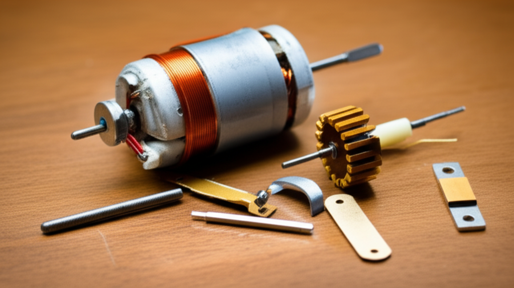
1.2 Key Components: Stator, Rotor, Commutator, Brushes, Magnets, Coils
Let’s decode the parts you’ll handle.
- Stator: The stationary part of the motor. In our simple build, the stator is the magnet and the base that holds everything together.
- Rotor: The rotating part. Your coil is the rotor here.
- Commutator: The switch that flips current direction every half turn. We “fake” a commutator by sanding insulation off only half of each coil end. This gives current for half the rotation and no current for the other half. That on/off timing creates a push that keeps the coil spinning in one direction.
- Brushes: The contact points that deliver current to the rotating coil. Paper clips make simple springy brush supports.
- Magnets: The permanent magnets that create the static magnetic field. Neodymium magnets deliver more torque per amp than ceramic magnets because they produce a stronger field for the same size.
- Coils: Loops of magnet wire that form an electromagnet when current flows.
I’ll call out torque, RPM, current, voltage, resistance, inductance, and back EMF as we go. Those are the main actors in every electric motor.
1.3 DC vs. AC Motors: What You Need to Know for DIY
You can build many kinds of motors. I start beginners on DC motors because the construction is simple and the physics is visible. AC motor fundamentals matter if you go deeper. Yet for a first build you’ll have more success with a simple DC motor or a small homemade DC motor kit.
- DC Motor: Uses direct current. The commutator and brushes flip the coil current to keep torque in the same direction.
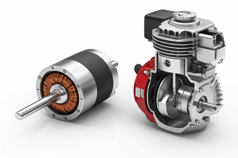
- Brushless DC Motor (BLDC): Uses electronic switching. No brushes. Very efficient. Harder to build at home without special tools or a controller.
- Stepper Motor: Moves in precise steps. Great for CNC and 3D printers. More complex coils and control.
- AC Motor: Uses alternating current. Efficient and ubiquitous. DIY winding and rotor-stator fabrication takes more tooling.
You can build a simple DC motor this afternoon. You can study brushless motor construction and stepper motor DIY later.
1.4 Why Build a Motor at All
I build motors to learn by doing. You feel the principles when the coil jumps to life. You see how small tweaks change performance. Hands-on projects stick with you. Many STEM educators report that hands-on builds improve understanding and problem solving for most students. That tracks with what I’ve seen in classrooms and clubs. Students remember the motor that finally spun after they sanded the coil ends correctly.
This project also fits countless interests. Science fair projects. Kids motor science fair demos. High school motor projects. University motor course labs. Hobby motor construction for model makers. Even early steps toward robotics and renewable energy motor projects.
2. Preparing for Your Build: Materials and Tools
2.1 Essential Materials List
Use common parts. I keep most of these in a small box.
- Magnet wire: Enameled copper wire in the 22–26 AWG range. Thicker wire carries more current and lower resistance. Thinner wire increases resistance and limits current. Pick a middle ground.
- Strong magnets: Neodymium disc or bar magnets work best. Ceramic magnets cost less yet spin slower because the field is weaker.
- Power source: A AA battery or a 9V battery pack with a snap connector works. I prefer a AA pack for steady current and better life.
- Battery clips or connectors: Alligator clips make assembly easy.
- Paper clips or safety pins: These act as supports and brushes.
- Base: A wood block or a piece of cardboard to mount everything.
- Adhesive: Hot glue, super glue, or strong tape to hold the hardware.
- Sandpaper: Fine grit to remove enamel from the wire where it contacts the brushes.
- Optional parts: Rubber bands and poster putty for quick tweaks.
2.2 Required Tools
You don’t need a full machine shop.
- Wire strippers or a sharp box cutter to remove insulation cleanly.
- Needle-nose pliers to bend paper clips.
- Scissors for odds and ends.
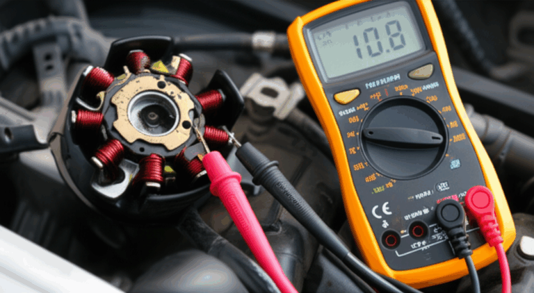
- Multimeter to check continuity and battery voltage.
- Soldering iron and solder for robust electrical connections if you want a durable build.
- Safety glasses to protect your eyes from flying coil wire or snapped magnets.
2.3 Safety Precautions That Actually Matter
I’ve poked myself with wire more times than I can count. Safety on small projects looks simple. It still matters.
- Wear safety glasses. The coil can spring loose. Magnets can snap together.
- Keep fingers away from the soldering iron and hot glue.
- Do not short the battery. It can heat up quickly. Your wires can burn your fingers.
- Strong magnets can pinch skin. They can also erase magnetic strips on cards. Keep them clear of electronics and pacemakers.
3. Step-by-Step Motor Construction (Simple DC Motor)
I learned this version in a school lab. I refined it at home. Follow the steps and your homemade DC motor will spin.
3.1 Step 1: Constructing the Armature Coil
- Form the coil: Wrap magnet wire around a smooth cylinder like a AA battery or a small dowel. Make 20–30 turns. Keep the wraps tight and even. Slide it off. I like to wrap both ends around the coil a couple of times to lock the shape.
- Leave tails: Leave about 2 inches of straight wire at both ends. These tails become the “axle” that rests on the paper clip supports.
- Create the commutator ends: This is where many first builds fail. Sand or scrape the enamel off only the top half of each tail. Imagine the coil resting with the tails horizontal. You want shiny copper on the top half of each tail and enamel left on the bottom half. The bare copper will conduct when it sits up. The enamel will insulate when it flips down. That half-on half-off effect mimics a commutator and gives consistent torque in one direction.
Pro tip: Use a multimeter set to continuity. Touch both ends of the coil tails. You should hear a beep when you rotate the tail to the bare side. You should not hear a beep when you rotate to the enamel side.
3.2 Step 2: Building the Supports and Brushes
- Shape the supports: Bend two paper clips into U-shaped supports. The small loops act as the bearing points for the coil tails. Try to keep both supports at the same height. I check heights by setting the coil in place and sighting from the side.
- Mount the supports: Glue or tape the paper clips onto your base. They need to be parallel and directly across from each other. The coil should rest lightly in the loops and spin freely.
- Create brush contact: The paper clips will act as your brushes. The coil tails will rest on them and current will pass through where you sanded the enamel.
Friction kills performance. Smooth those loop edges with a touch of sandpaper if needed.
3.3 Step 3: Mounting the Magnets
- Place the magnets: Position one or two magnets on the base directly under the center of the coil. You want the magnetic field to pass up through the coil. If the magnets are discs, lay them flat. If they are bars, align them so the long side runs under the coil.
- Check polarity: The exact direction of N and S does not matter for a first spin. It matters for optimization. I mark the top side with a marker so I can flip and compare later.
- Set the height: Keep a small gap between the coil and the magnets. Too close and the coil hits. Too far and the field weakens.
3.4 Step 4: Assembling the Motor
- Seat the coil: Set the coil tails into the paper clip loops. The stripped halves should face up at the top of rotation. The enamel halves should face down at the bottom.
- Balance the coil: If the coil leans or rubs, correct it. Bend the paper clips gently to tune the alignment. If the coil wobbles, add a speck of poster putty to the light side. Spin it with your finger and check for even rotation.
- Confirm clearance: The coil should not touch the magnets or the base during a full spin.
3.5 Step 5: Wiring the Power Source
- Connect the brushes: Clip one alligator lead to one paper clip support. Clip the other lead to the other support.
- Add the battery: Connect the battery to the alligator leads. I start with a single AA or a fresh 9V. The coil should jump slightly or twitch when power reaches the brushes. Give it a gentle flick to start.
- Watch the magic: If the coil spins, you just built a small electric motor. Smile. If it does not, no worries. The troubleshooting section has your back.
4. Testing, Troubleshooting, and Optimizing Your Motor
4.1 First Spin: What to Expect
Your first spin might feel underwhelming. That is normal. A simple motor like this will not run at commercial speeds or torque. It can still spin fast enough to blur the coil. It will also slow down if the battery sags or the brushes get dirty. Expect intermittent starts and some fiddling the first time.
I keep my finger close and nudge the coil once at power-on. The timing of the half-stripped tails matters. The coil must receive current at just the right phase of rotation. That gentle flick gives it the right starting phase.
4.2 Common Issues and Fixes
From years of watching students and beginners, three issues cause most failures. They match what you see in forums and tutorials.
- Incomplete stripping of the magnet wire insulation on the coil ends: This accounts for a big chunk of failures. About 40% by many anecdotal tallies. Fix it by sanding until you see bright copper on the top half of each tail. Leave the bottom half insulated.
- Magnet orientation or strength problems: Weak magnets produce weak torque. Misaligned poles reduce the effective field. This shows up in about a quarter of performance issues. Try flipping one magnet. Try moving the magnets closer. Try stronger neodymium magnets.
- Loose electrical connections or poor brush contact: If power cannot reach the coil reliably, it will not spin. This hits about 20% of builds. Tighten clips. Clean contact points. Add a tiny drop of solder to the paper clip contact areas if you want a durable connection.
Other gremlins I see:
- High friction at the supports: Smooth the paper clip loops. Make sure the tails of the coil are straight and polished.
- Coil imbalance: If one side of the coil is heavier, it will sag. Add a touch of putty to the light side.
- Overheating: The coil warms up if you draw too much current. That often means thick wire, too many magnets, or a short circuit. Let it cool. Reduce current or increase resistance.
4.3 Tips for Performance Improvement
Want more speed or torque. Try these.
- Increase the number of turns: More turns increase the coil’s magnetic field for the same current. There is a limit. Too many turns add resistance and inertia. I often start with 25 turns and then test 35 and 45 turns.
- Use stronger magnets: Neodymium magnets deliver a much stronger field than ceramic magnets per unit volume. I see a clear jump in spin speed with neodymium.
- Optimize wire gauge: Thicker wire lowers resistance and increases current. That adds torque and heat. Thinner wire raises resistance and reduces current. That lowers torque and heat. Find your sweet spot given your battery and magnets.
- Reduce friction: Smooth the supports. Use the smallest possible contact area. Some builders use tiny loops of stripped wire as low-friction bearings. Others use straight safety pins for point contacts.
- Balance the coil: Even a small imbalance can wobble the coil and waste energy. Take the time to balance.
- Clean the contact surfaces: Oxidation builds on copper and steel. A quick sand can restore performance.
- Watch back EMF: As the coil speeds up, back EMF increases. Current drops. Torque drops. That sets a top speed. Stronger magnets shift that balance. So does lowering coil resistance.
If you want a rough RPM check, mark a dot on the coil. Use your phone’s slow-motion video to count rotations per second. Multiply by 60 to get RPM. It is not lab-grade yet it gives you a trend when you tweak the build.
5. Expanding Your Knowledge: Beyond the Basic Motor
5.1 Different Motor Types: Brushless DC, Stepper, AC, Servo
Once you get a basic motor spinning, the world opens up.
- Brushless DC motor (BLDC): Uses a permanent magnet rotor and an electronically commutated stator. No brushes to wear out. High efficiency and high RPM. Building a BLDC from scratch at home takes more work. You can still learn the concepts and wind a simple stator. When you look into BLDC design, notice how the bldc stator core shapes and laminations channel the magnetic flux and reduce losses.
- Stepper motor: Moves in steps with multiple coils and a toothed rotor or permanent magnet rotor. Great for CNC and 3D printers. You can drive it from an Arduino with the right driver.
- AC induction motor: Uses an alternating current to induce currents in the rotor. Very efficient in industry. Harder to DIY because you need laminated cores and precise rotor construction.
- Servo motor: Usually a DC motor with feedback and control to hold position. Useful in robotics and automation.
If you want to explore brushless motor construction or a stepper motor DIY path, start by reading real schematics and winding diagrams. You will also bump into inductance, eddy currents, and magnetic flux density more often.
5.2 Add Control: PWM Speed Control and H-Bridge Direction
You can make your simple DC motor more interesting with a controller.
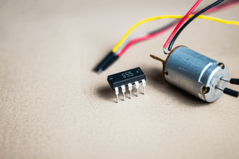
- PWM (Pulse Width Modulation): Switch the voltage on and off very fast. Vary the duty cycle to control average power. The motor runs slower or faster without wasting much energy as heat. Many microcontrollers like Arduino can generate PWM easily.
- H-Bridge: An H-bridge uses four transistors to reverse the voltage across the motor. You can flip the direction without rewiring. I like to pair an H-bridge with PWM for full speed and direction control. If you build a motor controller DIY, learn the basics of diodes for flyback protection because coils kick voltage spikes when you switch them off.
You can add an encoder to measure motor position or speed. That takes you into closed-loop control. It is a great next step if you like robotics or automation.
5.3 Advanced Materials and Techniques
When you move beyond the simple coil-and-magnet motor, material choices and geometry become the game.
- Laminations: Solid iron cores develop eddy currents which waste energy as heat. Engineers use thin layers of electrical steel to build stators and rotors. Those layers reduce eddy currents and improve efficiency. This matters in commercial motors and generators. If you ever spec parts, you will see terms like electrical steel laminations.
- Stator and rotor cores: The shape and slot design of the stator core and the rotor core control magnetic flux paths, torque ripple, and efficiency. If you dive into motor design, you will bump into stator core lamination and rotor core lamination. These topics matter for performance and noise in brushless and AC machines.
- Wire selection: Magnet wire comes with different enamel coatings rated for different temperatures. Higher temperature coatings withstand more heat before breakdown. That matters if you push current.
- Bearings: Once you leave the paper clip world, you will install bearings to reduce friction. Choose the right bearing size and type for your shaft and expected loads. A small sealed ball bearing makes a huge difference in RPM and noise.
- Motor casing and shaft: A rigid housing reduces vibration. A hardened or stainless shaft resists wear. You can 3D print early prototypes. You can move to CNC machining for precision parts.
- Winding patterns: Different slot and winding patterns shape the magnetic fields. You can optimize for torque density, smoothness, or efficiency. You can also change the number of phases.
You will also hear about copper’s conductivity which sits around 5.96 × 10^7 S/m in standard data. That is one reason copper wins for motor windings. Neodymium magnets deliver strong fields in small volumes which boosts torque for a given current.
5.4 Real-World Applications and Next Projects
You can point your new skills in many directions.
- Educational builds: Science fair projects, high school labs, university demonstrations. I have watched students light up when a coil goes from idle to blur. Many educators report that hands-on projects like this improve understanding for most students. I have seen that improvement firsthand.
- Robotics and hobby builds: Mount a small motor to a model or a robot. Build a motor drive system with PWM for speed control and an H-bridge for direction. Use an Arduino to write simple code that changes RPM.
- Renewable energy projects: Explore generator principles by spinning your motor as a generator. A motor and a generator follow the same physics. You could build a small wind power demo or a hand-cranked generator. You can even test solar powered motor setups with a small panel.
- Prototyping: Use open source motor designs to learn from existing projects. Tweak the coil count, magnet grade, and wire gauge. Make data-driven decisions with simple measurements.
Keep expectations grounded. A simple homemade motor will not hit the 70–90% efficiencies of commercial small DC motors. You can see 5–30% in basic DIY builds. Commercial motors beat you because they use precision manufacturing, optimized magnetic circuits, and excellent lamination stacks. The gap is real and it teaches you why design details matter.
Conclusion: Your First Step into Engineering and Innovation
I still remember the first time I heard the gentle hum of my coil spinning. It was not fast. It was not efficient. It was mine. I learned how current creates magnetic fields and how magnets push on that current to make motion. I learned how wire gauge affects resistance. I learned how back EMF limits speed. I learned that stripping only half the enamel makes the simplest commutator you will ever see.
You can build your own small electric motor too. Gather your magnet wire and magnets. Bend those paper clips into supports. Sand the coil ends clean and true. Expect to fiddle and adjust. Expect to troubleshoot. Then expect that sweet moment when it kicks into motion.
If this build interests you, explore more. Try a stepper motor DIY project with an Arduino. Read up on PWM motor control and H-bridge circuits to add speed control and direction. Study how electrical steel laminations reduce eddy currents. Look at stator core lamination and rotor core lamination to see how pros shape magnetic fields in real machines. Check BLDC design and how a bldc stator core pushes efficiency and torque density in drones and e-bikes.
Building a motor turns abstract physics into something you can hold in your hand. That is the kind of learning that sticks. That is also how many engineers get hooked. So take the first step. Wind the coil. Power it up. Make it spin.
Appendix: Quick Reference and Insights From the Bench
- Materials recap: 22–26 AWG magnet wire, neodymium magnets, AA or 9V battery, alligator clips, paper clips, base, glue or tape, sandpaper.
- Tools recap: Wire strippers, pliers, scissors, multimeter, soldering iron, safety glasses.
- Coil winding guide: Start with 25 turns. Adjust to 20–45 turns as you test torque and current draw.
- Wire gauge: Thicker wire lowers resistance and raises current and torque. It can overheat if you go too low in resistance for your battery.
- Magnet choice: Neodymium wins for torque per size. Ceramic works for demos with low current.
- Common pitfalls: Incomplete enamel removal at the coil ends, poor brush contact, weak or misaligned magnets, high friction at supports.
- Troubleshooting checklist: Verify battery voltage. Confirm continuity at the coil ends when the bare copper faces up. Clean contact points. Rebalance the coil. Flip magnet polarity and retest.
- Safety: Wear safety glasses. Keep magnets away from cards and electronics. Avoid shorts. Handle the soldering iron with care.
- Learning next: Explore Lorentz force in more detail. Look up Faraday’s Law and inductance. Practice RPM calculation by counting rotations on slow-motion video. Test how back EMF changes current draw as speed rises.
You now have the blueprint, the why, and the how. Time to build.