How Motor Core Laminations Drive Three-Phase Motor Performance: Materials, Processes, and Practical Choices
Every design engineer faces the same question sooner or later. How do you hit efficiency targets and thermal limits without blowing the budget on exotic materials or slow manufacturing methods. If you design, source, or specify three-phase motors you live at that intersection. You also know that stator and rotor lamination choices ripple outward into wiring strategy, starter selection, VFD performance, and real-world reliability.
This guide helps you decide with confidence. We break down the physics behind core losses, translate standards into practical constraints, and map materials and processes to common applications like pumps, compressors, conveyors, machine tools, and HVAC systems. Along the way we connect lamination choices to wiring realities like star (wye) vs delta connections, motor starter wiring, overload protection, and VFD integration. You’ll walk away with clear trade-offs, example use cases, and a short list of next steps you can take today.
In This Article
- Why Lamination Material Choice Is Critical
- Understanding Core Losses: Eddy Currents and Hysteresis
- From Nameplate to Winding: How System Choices Affect the Core
- Material Options for Motor Laminations
- Manufacturing and Assembly Processes That Shape Performance
- Which Application Is This For
- Wiring, Protection, and Testing Touchpoints Every Designer Should Consider
- Common Mistakes and How to Troubleshoot Performance
- Standards and Data You Can Trust
- Your Engineering Takeaway and Next Steps
Why Lamination Material Choice Is Critical
Motor lamination stacks aren’t just metal rings. They are the backbone of your magnetic circuit. Their thickness, alloy, coating, and stacking method set the floor for core losses, torque density, and thermal behavior. Choose well and you lower watts lost to heat which improves efficiency and extends service life. Choose poorly and you fight overheating, higher amperage draw, harsher acoustic noise, and rising costs for the life of the product.
Three-phase motors live on a steady diet of alternating magnetic fields. Laminations break the core into insulated slices that block large circulating currents inside the steel. Those “eddy currents” waste energy and create heat. Thinner laminations limit those currents which cuts loss at 50/60 Hz and under PWM drives. Material purity and silicon content also matter because they reduce hysteresis loss which is the energy spent flipping magnetic domains each cycle.
This is not just lab talk. Real installations with VFD wiring for a 3 phase motor see higher-frequency content and more harmonics. Those harmonics raise core losses in both stator and rotor stacks. The right electrical steel and a thoughtful manufacturing process keep efficiency where your nameplate says it should be.
If you need a quick refresher on the lamination building blocks themselves see these primers:
- Overview of motor core materials and stacks: motor core laminations
- Stator-specific considerations and options: stator core lamination
- Rotor bar paths, skew, and stack behavior: rotor core lamination
Understanding Core Losses: Eddy Currents and Hysteresis
Let’s demystify the forces at play. When you energize a three-phase stator, a rotating magnetic field sweeps through the core. The core pushes back in two main ways.
- Eddy current loss: Picture a river with whirlpools. A changing magnetic field induces circular currents inside the steel which act like little whirlpools of electricity. Those currents create heat and waste power. Thinner, well-insulated laminations break up those currents. That is why moving from 0.65 mm to 0.35 mm laminations often cuts loss in high-speed or VFD-heavy applications.
- Hysteresis loss: Every cycle the magnetic domains in the steel flip. That flip takes energy. The area inside the B-H curve represents that energy per cycle. Lower coercivity materials have slimmer loops which means less loss. Silicon in steel raises electrical resistivity and reduces hysteresis loss which is why “silicon steel” dominates motor cores.
A few more fundamentals matter:
- Frequency: Loss scales with frequency. A standard 50/60 Hz motor runs at predictable core loss. A VFD throws in higher switching frequencies and harmonic content which raises both eddy and hysteresis losses. This drives you toward thinner laminations and cleaner steels for high-frequency or wide-speed-range designs.
- Flux density: Run too close to saturation and loss goes up sharply. Delta connection in a 3 phase motor gives lower phase voltage per coil on dual-rated nameplates which can change the flux density in the teeth and yoke. Star connection can suit higher line voltage with lower current per winding which can keep flux density where you want it if your lamination stack is sized right.
- Temperature: Core loss turns into heat. Heat changes resistance and can degrade insulation over time. Keep an eye on insulation class, ambient temperature, and service factor on the motor nameplate. Thermal headroom lets you handle overloads and real-world voltage imbalance without cooking the core.
Quick analogy you can share with non-specialists: Magnetic permeability works like a sponge for magnetic field lines. High permeability materials let flux pass easily just like a sponge soaks water. Coercivity acts like the stiffness of that sponge. A stiff sponge needs more force to squeeze and release which wastes energy.
From Nameplate to Winding: How System Choices Affect the Core
Most wiring and control decisions show up in the core. Not directly as a wire or a screw but as thermal and magnetic stress. You can read the clues on the nameplate then map them to the lamination strategy.
- Voltage ratings and connection types: Dual-rated motors often show 230/400V or 460/480V. At the terminal block you can wire in star (wye) for the higher voltage or delta for the lower voltage. A 6-lead or 9-lead design sets the options. The choice alters phase voltage which shifts flux density in the core. Get that wrong and you increase core loss or lose torque.
- Frequency and RPM: 50 Hz vs 60 Hz moves your synchronous speed and loss baseline. Higher base frequency drives you toward thinner laminations or better grades.
- HP/kW, FLA, service factor: Higher FLA and service factor translate to more heat in both copper and steel. The lamination stack must move that heat out with proper slot fill and surface area. This isn’t only a winding problem.
- Starting method: Direct On Line starter wiring (DOL) brings high inrush current and high slip. Wye-delta starter wiring softens the hit but changes the electrical stress pattern. Soft starter integration reduces mechanical shock which helps rotor bar integrity and reduces vibration that can loosen stacks. Autotransformer starter wiring offers another reduced-voltage approach that curbs inrush and may help large motors on weak feeders. Each method changes heating during start which feeds back into lamination thickness and coating selection.
- VFD use: A variable frequency drive connection expands your speed range and boosts efficiency at part load. It also injects harmonic content and higher dv/dt which raise core and stray losses. Expect more attention to thin NGO silicon steel, better interlaminate insulation, and tighter control of burrs and shorts. Proper VFD wiring for a 3 phase motor with shielded cables and grounding protects bearings and keeps EMI in check which preserves your design intent.
- Application dynamics: High inertia loads like large conveyors or flywheels demand longer starts and higher slip. That stretches rotor and stator heating. Low inertia ventilation fans reach speed quickly which reduces start loss but can see wide speed operation under VFDs. Both cases lean on lamination decisions.
When you interpret a motor nameplate you aren’t just picking overload relay settings. You’re also deciding how hard the magnetic circuit will work day in and day out.
Material Options for Motor Laminations
You have several levers to pull on the materials side. Here’s a practical view.
- Non-oriented silicon steel (NGO) M-grades
- Best for general-purpose three-phase induction motors and many synchronous designs.
- Pros: Balanced cost and performance. Widely available. Good loss figures at 50/60 Hz. Stable mechanical properties.
- Cons: Loss rises with frequency. Performance varies by grade and thickness. Watch quality for consistent coating and flatness.
- Use cases: Pumps, compressors, conveyor motors, machine tools, HVAC 3 phase motors, ventilation fan drives.
- High-grade NGO silicon steel for VFD or high-efficiency motors
- Pros: Lower core loss, improved permeability, tighter thickness control. Better suited for wide-range VFD operation and high motor efficiency ratings.
- Cons: Higher cost and longer lead times in some regions.
- Use cases: IE3/IE4 efficiency motors, small 3 phase motor wiring scenarios with tight thermal envelopes, machine tool spindles with high base speeds.
- Cobalt-iron alloys
- Pros: Very high saturation flux density and good high-frequency behavior. Great for high power density and aerospace.
- Cons: Expensive and tougher on tooling. Not needed in most industrial motors.
- Use cases: Specialized synchronous motors and permanent magnet 3 phase motor designs where torque density rules.
- Grain-oriented electrical steel
- Pros: Extremely low loss in the rolling direction.
- Cons: Anisotropic behavior makes it poor for rotating machines. Great for transformers not motors.
- Use cases: Transformers and inductors. If your project crosses over you can study a transformer lamination core for those needs.
- Amorphous or nanocrystalline materials
- Pros: Very low core loss at higher frequencies.
- Cons: Expensive, brittle, and not usually practical for standard motor stacks.
- Use cases: Specialized high-frequency devices not common in mainstream motor stators or rotors.
- Insulation coating classes for laminations
- Coatings maintain interlaminate insulation which blocks eddy currents. They also aid punching and stacking. Choose coatings with the right thermal class and bonding behavior if you use bonding or interlocking.
If you want a crisp overview of the material family and its trade-offs visit this quick resource on electrical steel laminations and the deeper dive on silicon steel laminations.
How to choose thickness
- 0.65 mm: Standard for many low-cost 50/60 Hz motors where VFD use is limited or absent.
- 0.50 mm: A balanced option when you need lower loss without exotic cost.
- 0.35 mm to 0.27 mm: For high-efficiency or VFD-heavy duty cycles where harmonic losses matter. Helps high-speed and high-pole-count designs.
- 0.20 mm and thinner: Specialty territory. Consider only when your frequency or harmonic content justifies it.
Tie the choice back to real requirements. Chasing the lowest core loss number can increase tooling wear, slow throughput, and inflate cost. Match the grade and thickness to your efficiency target and your actual operating spectrum.
Manufacturing and Assembly Processes That Shape Performance
Material gets you halfway there. How you cut, stack, and secure the laminations often decides whether the lab data shows up in the field.
Cutting methods
- Progressive die stamping: The workhorse for high-volume production. Low cost per piece after tooling. Consistent dimensions and burr control with good die maintenance. Watch for die wear which raises burrs and risks interlaminate shorts.
- Laser cutting: Ideal for prototyping, short runs, or complex geometries. No hard tooling. Some heat affected zone that can increase local loss. You can mitigate with post-cut anneal in sensitive designs.
- Wire EDM and fine blanking: Niche options when you need superb accuracy or burr-free edges for specialized geometries.
Stacking and joining
- Interlocking laminations: Tabs and notches click together like LEGO bricks. No welding required. Good for throughput and structural integrity. Watch tab geometry to avoid magnetic leakage or stress risers.
- Bonding/varnish: Adhesive or insulating varnish between layers creates quiet stacks with low vibration. Great for low noise and high integrity cores. You need process control for cure schedules and cleanliness.
- Riveting or cleating: Simple and robust. Adds local mechanical stress and can affect local flux. Use sparingly or away from high-flux areas.
- Welding: Strong mechanical joints but heat and metallurgical changes can increase local loss. Reserve for structural needs and manage heat input.
Stress relief and annealing
- Stamping and cutting introduce residual stress that raises loss. Post-stamp anneal can recover performance especially for high-efficiency designs. Balance this with throughput and cost.
Skew and slot geometry
- Stator slot skew reduces cogging and torque ripple which drops acoustic noise. Rotor skew can improve smoothness and reduce harmonic torques. Both interact with rotor bar conductivity and slot fills which influence losses and vibration.
Rotor considerations
- For squirrel cage induction motors, rotor bar material and end ring design change rotor heating at start and under slip. Rotor lamination skew and shorting ring design influence starting torque and noise. Keep the lamination stack quality high because rotor eddy currents under VFDs rise with harmonic content.
Quality levers to watch
- Burr height control and 100% visual checks for shorts at the edges.
- Coating integrity across the whole stack.
- Stack pressure and height tolerance.
- Runout and concentricity that affect air-gap uniformity which changes core local flux density.
Which Application Is This For
Fit drives everything. Here’s how to match lamination choices to common three-phase motor applications and connection practices.
Pumps and compressors
- Duty: Long runs at near constant speed. Occasional starts. DOL or soft starter common. VFD adoption rising for energy savings.
- Lamination choice: NGO silicon steel at 0.50 mm or 0.35 mm when efficiency mandates it. Skew for quieter operation. Bonded stacks help with tonal noise.
- Wiring reality: For 230/400V or 460/480V nameplates choose star connection 3 phase motor at higher supply voltage and delta at lower. Magnetic starter wiring with well-calibrated overload relays prevents nuisance trips.
Conveyors and material handling
- Duty: Frequent starts and stops, variable loads, high inertia starts in some cases.
- Lamination choice: Slightly thicker laminations can handle thermal swings though higher efficiency grades pay off if a VFD controls speed. Rotor skew helps reduce torsional ripple.
- Wiring reality: Reduced voltage starting motor methods like autotransformer starter wiring save the feeder from voltage sags. Phase loss protection protects the motor if a contactor pole fails.
Machine tools
- Duty: Wide speed range, tight torque ripple limits, sometimes high base speeds.
- Lamination choice: High-grade NGO at 0.35 mm or thinner. Precise slot geometry and careful skew. Bonded stator stacks pay dividends in noise.
- Wiring reality: VFD wiring 3 phase motor becomes the norm. Keep cable shielding and grounding solid. Verify phase sequence before coupling to the spindle.
HVAC and ventilation fans
- Duty: Variable air volume and long run times. VFDs common. Low noise priority.
- Lamination choice: Efficient NGO steel and skew. Bonded stacks improve acoustics. For permanent magnet motors, manage high-frequency loss and temperature.
- Wiring reality: Motor control wiring includes remote start/stop and safety interlocks. Power factor correction may live at the panel or VFD input. Ensure proper disconnect switch ratings for maintenance.
Agricultural installations
- Duty: Dust, moisture, and wide ambient temperature swings.
- Lamination choice: Robust coatings and corrosion-resistant stack treatments. Conservative flux densities for reliability.
- Wiring reality: Junction box wiring needs careful sealing. Ground wire connection 3 phase motor is non-negotiable. Follow local wiring color codes 3 phase to reduce errors.
Small vs large 3 phase motor wiring environments
- Small 3 phase motors: 0.35 mm laminations gain efficiency without big cost. Often on VFDs in OEM machines. Tight space with integrated starters.
- Large 3 phase motors: Stamping with heavy-duty tooling and post-stamp anneal for loss control. Soft starters and MCC integration common.
Permanent magnet and synchronous designs
- PM motors: Higher flux and potential high-frequency content. Watch stator tooth and yoke flux density. Thin laminations and low-loss steel help.
- Synchronous motors: Field excitation or PM field. Lamination cleanliness and slot geometry control saliency and torque ripple.
Wiring, Protection, and Testing Touchpoints Every Designer Should Consider
You might not pull wire in the field yet your choices make the installer’s job easier and the motor’s life longer. Tie design details to these realities.
Planning and diagrams
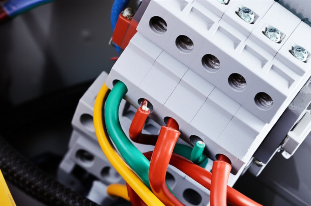
- A clear 3 phase motor wiring diagram reduces miswiring. Show star/wye vs delta jumpers for 6-lead and 9-lead cases. Include motor terminal block connections and torque specs.
- Note the correct 3 phase motor rotation and how to reverse it by swapping two phases. Encourage phase sequence checks during commissioning.
Power and protection
- Circuit breaker for 3 phase motor sizing and fuse sizing align with NEC Article 430 or IEC equivalents. Overcurrent protection 3 phase motor must clear faults fast without nuisance tripping.
- Motor overload relay wiring protects the motor from sustained overload or phase loss. Set it to 115–125% of FLA per NEC guidance for continuous duty unless the nameplate says otherwise.
- Disconnect switch 3 phase motor near the machine aids lockout tagout procedures and speeds maintenance. Specify disconnect switch ratings that match the fault current and motor load.
Starters and drives
- Direct On Line starter wiring fits rugged loads on stiff power. Use reduced voltage starting motor methods like soft starters if water hammer or belt shock matters.
- Wye-delta starter wiring helps large motors with line limitations. Just remember the starter adds complexity to the control circuit wiring.
- VFD wiring 3 phase motor demands shielded motor leads, proper grounding, and sometimes dv/dt filters or sine wave filters. PWM raises core and stray losses which your lamination choice must tolerate. For long lead runs consider common-mode chokes to protect bearings.
Conductors and installation
- Wire gauge for 3 phase motor depends on FLA, insulation temp rating, ambient temperature, and conduit fill. Voltage drop calculations matter over long runs because low voltage raises current and heat.
- Conduit sizing charts and conduit fill capacity affect heat dissipation around the conductors. Conduit bending techniques that avoid sharp kinks protect insulation.
- Crimping electrical terminals with the right dies and using a torque wrench in electrical work keep terminations tight which avoids hot spots that can mimic higher core loss symptoms.
- Use heat shrink tubing and appropriate electrical tape applications to seal terminations. Wire labeling best practices save hours during troubleshooting.
- Follow NEMA motor wiring standards or IEC motor wiring standards and wiring color codes 3 phase in your region. International wiring standards exist for a reason.
Testing and commissioning
- Verify de-energized circuits. Lockout/tagout and PPE come first.
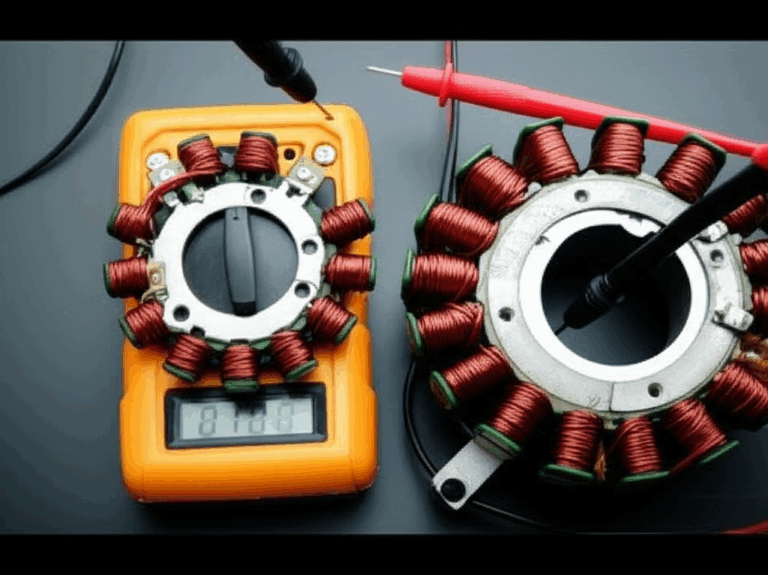
- Multimeter testing 3 phase verifies voltage at the terminals. A phase rotation meter confirms rotation before coupling the load.
- Insulation resistance testing with a megohmmeter after installation protects you from early shorts. IEEE Std 43 gives you a baseline for acceptable values.
- Measure amperage draw 3 phase motor at first start then compare to nameplate FLA. Imbalance hints at wiring, load, or supply issues.
- If a motor hum appears or overheating shows up at low load, evaluate voltage imbalance, phase sequence, and starter settings first before you blame laminations.
System-level details
- Panel board wiring 3 phase and motor control center wiring should keep control and power separated to reduce noise. Use proper raceway or conduit to protect runs.
- Phase loss protection and open phase detection devices save motors from single-phasing which spikes current and heat.
- Power factor correction 3 phase may live upstream. Motors with higher efficiency and better core materials often run with improved power factor yet correction caps still help across a plant.
Field realities that impact the core
- Loose connections lead to undervoltage at the motor which drives current up. That raises I²R heat in copper and pushes core into higher loss regions at the same time.
- Ambient heat and poor airflow around the motor enclosure raise internal temperature. Higher temperature accelerates insulation aging which can lead to ground faults that a good lamination stack can’t save you from.
Common Mistakes and How to Troubleshoot Performance
Mistake 1: Chasing the cheapest steel on a VFD-driven machine
- Symptom: Motor runs hot at mid speed under VFD. Efficiency falls short. Audible whine increases.
- Cause: Harmonic content drives up core losses. Standard 0.65 mm steel can’t keep up.
- Fix: Move to thinner NGO laminations with lower loss rating and improve interlaminate insulation. Add a filter or adjust drive switching frequency if needed.
Mistake 2: Underestimating start duty on high-inertia loads
- Symptom: Overheating during long starts. Rotor shows discoloration in teardown. Stator darkened near slots.
- Cause: Prolonged slip heats rotor bars and stator teeth. Laminations see extra cycle loss.
- Fix: Consider reduced voltage starting motor methods. Increase rotor skew or slot changes. Improve stack bonding to damp vibration.
Mistake 3: Poor burr control and lamination shorts
- Symptom: Unexplained no-load temperature rise. Higher iron loss than design.
- Cause: Burrs bridge insulation between laminations which creates eddy current paths.
- Fix: Tighten die maintenance. Deburr and inspect edges. Consider post-process coating or anneal.
Mistake 4: Misapplied star/delta connection
- Symptom: Low torque or excessive current at rated load. Overheating during normal operation.
- Cause: Wrong connection for supply voltage which changes phase voltage and flux density.
- Fix: Recheck the motor wiring diagram and nameplate. For a 230/400V nameplate use delta at 230V and star at 400V unless specified otherwise. Verify 6-lead or 9-lead configuration rules.
Mistake 5: Ignoring grounding and EMC on VFD systems
- Symptom: Bearing failures and nuisance trips. Temperature creep without clear cause.
- Cause: High-frequency currents find stray paths. Noise couples into control wiring.
- Fix: Use proper grounding and shielded cable. Follow drive vendor best practices. Add common-mode chokes or filters. Keep control circuit wiring separate from power.
Troubleshooting checklist
- Check phase sequence and correct 3 phase motor rotation before loading.
- Verify voltage at the motor terminals under load. Measure phase imbalance.
- Confirm overload relay settings and contactor wiring for 3 phase motor. Inspect magnetic starter wiring diagrams match the field.
- Run insulation resistance testing. Compare to baseline values.
- Survey connections with an infrared camera for hot spots. Loose lugs show up fast.
- If the motor hum persists after fixes, analyze vibration. Look for mechanical resonance or rotor bar issues. Align the machine and verify foundation and vibration isolation.
Standards and Data You Can Trust
Lean on standards to anchor decisions and specs.
- Motor and installation: NEMA MG 1 for motor design and ratings. NEC Article 430 for motor feeders and branch circuits in the US. IEC 60034 for rotating machinery and IEC 60364 for electrical installations internationally.
- Magnetic materials and testing: IEC 60404 series covers methods for measuring magnetic properties and classifying electrical steels. ASTM A677 for nonoriented electrical steel sheet and strip. ASTM A876 for grain-oriented sheet and strip.
- Insulation testing: IEEE Std 43 provides guidance for insulation resistance testing of rotating machines.
- Safety: OSHA and ESFI publications reinforce lockout/tagout and arc-flash PPE best practices.
You don’t need to quote them verbatim in every drawing. You do want your lamination supplier and panel builder to read from the same book.
Your Engineering Takeaway and Next Steps
Key points worth pinning to your whiteboard
- Laminations set your baseline efficiency and thermal behavior. Thinner and cleaner steels cut loss yet increase cost and process sensitivity.
- VFDs boost system efficiency and add harmonic heating. Match them with thin NGO steels and tight manufacturing control.
- Star/delta connection, starters, and protection settings all influence core stress. Read the nameplate and plan the wiring around your lamination limits.
- Manufacturing details like burr height, coating integrity, and stack joining can make or break your design in the field.
- Align materials and processes with the application. Pumps and fans want quiet, efficient stacks. High inertia systems want thermal robustness. Machine tools want low torque ripple and high-frequency performance.
Actionable next steps
- Define your operating spectrum. List base frequency, VFD range, duty cycle, ambient temperature, and expected starts per hour.
- Set an efficiency and temperature target at the motor frame level. Translate that to a maximum iron loss budget with your motor analyst or supplier.
- Pick a lamination thickness and grade that meets loss targets with margin. Start with 0.50 mm NGO, then move to 0.35 mm for tighter specs or VFD-heavy duty.
- Choose a manufacturing route that matches volume and tolerance. Progressive die for scale, laser for prototypes, bonding for quiet and rigid stacks.
- Lock in a wiring and protection approach early. Document star/delta jumper schemes, starter types, overload settings, and VFD filtering as part of your design package.
- Build a test plan. Include insulation resistance testing, phase rotation verification, no-load amperage checks, and thermal soak runs to validate iron loss predictions.
If you want to validate material and process options quickly share your duty cycle and efficiency targets with a lamination partner. A short conversation with an engineering team that builds motor core laminations every day will surface practical trade-offs fast.
Finally remember the big picture. The lamination stack is not a line item on a BOM. It is your magnetic engine block. Treat it that way and your next 3 phase motor design will run cooler, quieter, and longer with less drama at installation.
Appendix: Quick tie-ins to common search topics that brought you here
- How to connect 3 phase motor and reverse rotation: swap any two phases after you verify phase sequence.
- Single phase to 3 phase motor wiring in a home workshop: many VFDs accept single-phase input and output three-phase power for small motors. Size the drive generously and follow vendor wiring diagrams.
- Junction box wiring and motor terminal block connections: use marked jumpers for 6- or 9-lead motors. Label wires, torque lugs to spec, and apply heat shrink where needed.
- Overcurrent and overload protection: pick a circuit breaker for 3 phase motor or fuses per NEC/IEC tables and set the overload relay per nameplate FLA and duty.
- Testing tools: multimeter testing 3 phase, phase rotation meters, and megohmmeters for insulation resistance testing are your core kit.
Whether you build squirrel cage induction motor designs, synchronous 3 phase motor drives, or permanent magnet 3 phase motor systems the lamination choices drive performance. Choose materials and processes with intent and let the wiring, protection, and testing follow that plan.