How Many Volts Does a Stator Put Out? Your Essential Guide to Stator Performance
Table of Contents
- What This Guide Covers and Why It Matters
- What Is a Stator and How Does It Make Voltage?
- How Many Volts Does a Stator Put Out?
- Does RPM Change Stator Output?
- How Do You Test Stator AC Voltage Step by Step?
- How Do You Test Stator Resistance and Insulation?
- What Do These Test Results Mean?
- Is It the Stator or the Regulator/Rectifier or the Battery?
- Alternator vs Stator: What Is the Difference?
- What About Motorcycles, ATVs, Marine, and Small Engines?
- AC vs DC: What Reaches the Battery?
- How Many Wires on a Stator and What Do Colors Mean?
- What Tools and Settings Do I Need?
- Why Do Stators Fail and How Can You Prevent It?
- Can I Upgrade My Stator Output or Use Lithium?
- Case Study: Intermittent Output When Hot
- Output Charts, Specs by Make, and Trends
- Quick Safety Tips You Should Not Skip
- FAQ
- Summary: Key Points to Remember
- References
You asked a simple question. I will give you a clear answer. A stator makes AC volts for your charging system. The range changes with RPM and design. In this guide you will see normal readings, easy tests, and fixes. I will show you what to do if your battery is not charging. I will use plain words. I will keep it short and direct. You will leave with confidence.
What Is a Stator and How Does It Make Voltage?
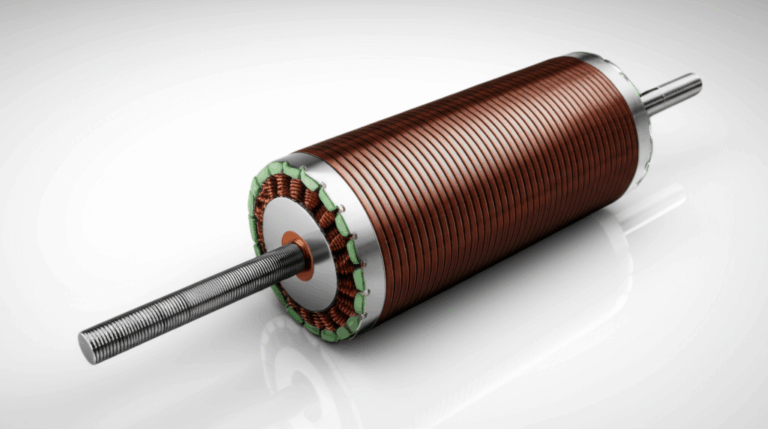
A stator is a set of fixed coils. Magnets spin past these coils on the rotor or flywheel. That spin cuts the magnetic field through the windings. This is electromagnetic induction. It makes AC volts. The stator is the primary AC power generator in many small engines, motorcycles, ATVs, outboard motors, snowmobiles, and generators.
The stator sits around the rotor. The rotor carries the magnets. The engine turns the rotor. The stator stays still. The coils sit on a steel core. The quality of the steel and the stack matters. Good stator core lamination lowers losses. It keeps heat down. It improves voltage and wattage. The rotor core matters too. Strong, well made rotor core lamination helps the magnetic field stay focused.
You should know this key point. The stator makes AC voltage. The rectifier turns that AC into DC. Then the voltage regulator holds the DC steady for the battery and ECU. The charging system needs all three: stator, rectifier, and regulator.
How Many Volts Does a Stator Put Out?
Here is the short answer. Many motorcycle and ATV stators make 20 to 30 Volts AC at idle. They rise to 40 to 70 Volts AC at 3,000 to 5,000 RPM per phase in a three phase stator. Small engines often make 15 to 30 VAC. Marine outboards can go higher with mid range at 40 to 80+ VAC per phase. Always read AC volts before the regulator/rectifier.
That range is normal for unloaded tests. Unloaded means the stator is disconnected from the regulator. It is open circuit stator test. You test volts AC right at the stator connector. When you meet the specs in your service manual you know the stator is OK. If not you test further.
The exact number depends on engine design, number of poles, coil configuration, and desired wattage. A bigger engine with more poles and better coil windings can push more volts at high RPM. It also depends on the core steel. Better electrical steel laminations reduce eddy losses.
Does RPM Change Stator Output?
Yes it does. Stator output voltage is directly proportional to engine RPM. Double the RPM and the AC volts roughly double. Idle gives a lower number. Mid range gives a higher number. Peak voltage from the stator rises with RPM. RMS voltage is what your meter reads on AC mode. If you use an oscilloscope you can see the sine wave, the peak voltage, and any noise.
Load also changes output. The impact of load on stator output shows as a small voltage drop when you connect the regulator and battery. The rectifier and regulator clamp voltage to protect the battery and electronics. That is normal.
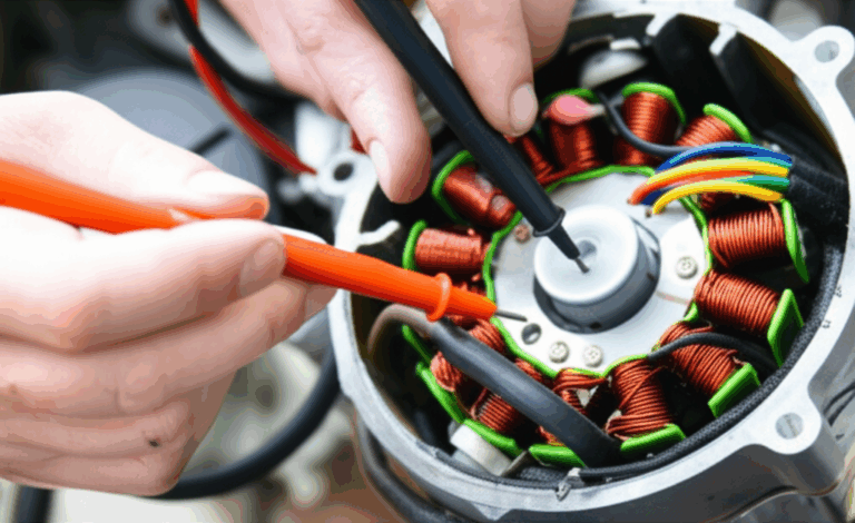
How Do You Test Stator AC Voltage Step by Step?
I follow this simple plan for a three phase system:
For a single phase stator:
Testing a motorcycle stator without removing it is common. You test at the connector. Be careful. Parts will be hot.
How Do You Test Stator Resistance and Insulation?
When the engine is off you switch the meter to Ohms. I use these two checks.
Stator resistance test between phases:
Insulation test to ground:
If you have access to a megger you can do a stator insulation resistance test at a higher voltage for a deeper check. Many DIY users stick to a good multimeter. That is fine for most cases.
What Do These Test Results Mean?
Low or no AC voltage output across all pairs often points to a failed stator. You may have an open circuit in the windings. You may have a short circuit between turns. You may have a weak rotor magnet. If only one pair is low and others are normal you likely have a shorted or open winding in one phase. Uneven AC voltage readings like 50V, 20V, 50V mean one phase is bad.
For Ohms tests:
- Infinite resistance between wires means an open winding.
- Any resistance to ground shows a short to engine casing.
- Readings far from spec suggest damaged windings or heat damage.
Sometimes the stator looks fine. Normal stator output with charging problems points to a bad regulator/rectifier or a weak battery. A charging system bypass test can help. You can also test the regulator rectifier with a diode test mode on your meter.
Is It the Stator or the Regulator/Rectifier or the Battery?
Think like a detective. Start at the stator. If the stator output is good in VAC and Ohms then move to the regulator/rectifier. You test the rectifier with the diode test. You test the regulator by watching DC volts at the battery with the system connected. Most bikes and ATVs should hold about 13.5 to 14.5 Volts DC at 3,000 RPM. That is volts DC after the rectifier converts and the regulator holds steady.
If battery voltage stays low you check the battery. A lead acid battery can be weak. A lithium ion battery needs a stable DC level. A bad cell can pull the system down. Check for a blown fuse or a tripped circuit breaker. Check the ground wire. Look for a corroded connector and a loose crimp. A charging system wiring diagram in the service manual helps a lot.
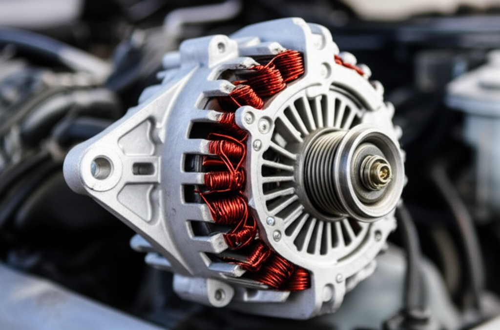
Alternator vs Stator: What Is the Difference?
People mix these terms. An alternator often means a full car style unit with a rotor field coil and a built in rectifier. A stator on bikes and small engines is more simple. You have fixed windings and a rotor with magnets on a flywheel. The rectifier and regulator sit outside.
The parts still act as a charging system. The alternator or stator makes AC. The rectifier makes DC. The regulator holds the level. The ECU and the ignition system need clean DC for spark and fuel injection systems. Lights, ABS, GPS, and heated gear need power too.
What About Motorcycles, ATVs, Marine, and Small Engines?
Let’s walk through normal readings across common rides.
Motorcycles and ATVs:
- Stator AC voltage output often reads 20 to 30 VAC at idle per phase.
- At 3,000 to 5,000 RPM it rises to 40 to 70 VAC.
- Three phase stator output is common. Some older bikes use single phase.
UTVs and dirt bikes:
- Similar to motorcycles. They face more dust and mud. Keep connectors clean.
Marine outboards and personal watercraft:
- Outboard stator voltage output can run from 25 VAC at idle to 60 to 80+ VAC at mid range per phase.
- Marine engine charging systems live in salt and damp air. Corrosion risk is high. Keep connectors tight and dry.
Small engines like lawn mowers and generators:
- Small engine stator output usually sits between 15 and 30 VAC at operating speed.
- Some run single phase. Some run low output three phase. Lawn mower stator output feeds small lights and charging.
Snowmobile stator voltage test:
- Tests match the motorcycle steps. Expect ranges like 20 to 30 VAC at idle and 40 to 70 VAC at test RPM if three phase.
Wind turbines and hydroelectric generator stators:
- These can be custom systems. Output depends on design, rotor speed, and magnetic poles. The principle stays the same.
AC vs DC: What Reaches the Battery?
Volts AC vs DC stator output can confuse people. The stator makes AC volts. The rectifier turns AC to DC. The regulator holds DC at a safe level for the battery and electronics. What voltage is safe for electronics depends on the device. Most 12V systems want about 13.5 to 14.5 VDC while charging.
If you measure at the battery you set the meter to Volts DC. If you measure at the stator wires you set the meter to Volts AC. Rectifying stator output to DC is the rectifier’s job. Regulator function with stator is to clamp the DC level. That protects the battery and the ECU.
How Many Wires on a Stator and What Do Colors Mean?
A three wire stator means three phase. You test pairs. Often the wires are all yellow. Sometimes white or green. A two wire stator is single phase. You test across the pair. Testing 3 wire stator is like I showed above. Testing 2 wire stator is even simpler.
Stator wire colors can vary by brand. Always check the service manual for your make and model. Honda, Yamaha, Kawasaki, Suzuki, Polaris, and Can‑Am each have wiring charts. They publish specs and colors.
What Tools and Settings Do I Need?
You need a good digital multimeter. It should measure Volts AC and Volts DC. It should read low Ohms and have a diode test mode. A clamp meter can help with current. An oscilloscope is great for a deep look at waveform, peak voltage, and RMS voltage. You also need basic hand tools and a safe place to run the engine.
I keep a notepad for readings. I also keep a spark plug wrench, extra fuses, and a test light. I look over the wiring harness for cuts and rubs. I check the ground wire to the frame for rust. I inspect any connector to the rectifier regulator. I look at the flywheel and rotor if I need to go deeper.
Why Do Stators Fail and How Can You Prevent It?
Heat kills stators. Overheating is a leading cause of stator failure. High current draw and poor cooling bake the windings. The insulation breaks down. Stator coil short circuit can start between turns. The output drops. It may pass a cold test then fail hot.
You can prevent stator failure. Keep loads in check. Do not run too many heated accessories. Make sure the regulator has a good ground. Clean dirt off the engine so air can flow. Quality core matters too. Good motor core laminations and tight core lamination stacks limit eddy currents. They keep heat down. Stator cooling matters. Some designs use oil bath cooling. Keep oil level right. Listen for stator noise symptoms like whining that rises with RPM.
Can I Upgrade My Stator Output or Use Lithium?
Many riders want more watts for heated gear. You can upgrade stator output on some bikes with an aftermarket stator. Aftermarket stator output differences can be real. OEM stator output specs vary by year and model. Always match the regulator/rectifier. Make sure the wiring can handle more current.
Lithium batteries need a stable charge profile. Stator output for lithium battery use should pair with a lithium safe regulator. Ask the maker. For fuel injection systems you must keep DC stable. The ECU and injectors hate low voltage. Modern bikes need more power for ABS, GPS, and comms. Industry trend shows increasing output requirements. Some systems now use a permanent magnet three phase stator with a MOSFET regulator.
Case Study: Intermittent Output When Hot
I once helped a rider with a 2008 Honda CBR600RR. Battery not charging after a ride. We saw borderline stator voltage output when cold. After a 30 minute ride we measured again. Output dropped from 55 VAC to 20–30 VAC and it was uneven across pairs. That matched a heat induced failure. We pulled the cover. The windings were dark. The stator failed when hot.
This kind of intermittent stator output can drive you nuts. Do a cold test. Then do a hot test. If readings change a lot look for heat damage. You may need a new stator. Sometimes the rotor magnet weakens. Rare but it happens.
Output Charts, Specs by Make, and Trends
You can use a stator output chart to track idle and test RPM. Stator output comparison across bikes helps you see what normal looks like. Always check the service manual for your exact stator output specification by make and model. Honda, Yamaha, Kawasaki, Suzuki, Harley‑Davidson, Polaris, and Can‑Am list exact numbers. Briggs & Stratton and Kohler list small engine specs. Cummins publishes generator data. Delphi and Bosch publish regulator and connector data. NGK helps with spark plug info if you chase misfires that look like low voltage.
Here is a simple table you can use. Values vary. Use your manual to confirm.
Typical Stator Output and Diagnostic Data
| Component / Parameter | Typical AC Voltage Output Range (Unloaded, Per Phase) | Typical Ohms Resistance (Cold, Between Phases) | Diagnostic Indicators / Notes |
|---|---|---|---|
| Motorcycle Stator (3-Phase) | 20–30 VAC (Idle ~1000 RPM); 40–70 VAC (3,000–5,000 RPM) | 0.1–0.5 Ω | Normal: Equal volts on all pairs. Voltage rises with RPM. Low/No Output: Open or shorted windings. Uneven Output: One phase fault. |
| ATV/UTV Stator (3-Phase) | 18–28 VAC (Idle); 35–65 VAC (3,000–5,000 RPM) | 0.1–0.7 Ω | Similar to motorcycles. Built for rugged use. |
| Marine Outboard Stator (3-Phase) | 15–30 VAC (Idle); 40–80+ VAC (~3000 RPM) | 0.2–1.5 Ω | Larger outboards handle more loads. Watch for corrosion risk. |
| Small Engine Stator (Single‑Phase) | 15–30 VAC (Operating RPM) | 0.5–3.0 Ω | Lower output for lights and charging. Test across two wires. |
| Stator to Ground Resistance | N/A | Infinite (OL) | Normal: No continuity to engine block. Fault: Any reading to ground shows insulation breakdown. |
Modern systems ask more from the charging system. Fuel pumps, ECU, ABS, heated gear, GPS, and radios all raise demand. Makers respond with higher wattage stators and stronger regulators. They also use better stator core lamination and refined silicon steel to reduce loss.
Quick Safety Tips You Should Not Skip
- Stay clear of the chain and belts when the engine runs.
- Watch hot exhaust and engine parts.
- Keep loose sleeves away from the rotor or flywheel.
- Use eye protection.
- Set the meter to the right range. VAC for stator. VDC for battery.
- Disconnect the battery ground when you unplug connectors to avoid a short.
PAS: Problem, Agitate, Solution in Plain Terms
Problem: Your battery dies. Lights dim. The bike stalls at idle. You wonder how many volts your stator should put out. You feel stuck.
Agitate: You swap parts at random. You waste money. The ride sits in the garage. You miss a weekend trip. Cold mornings make the bike crank slow. That stings.
Solution: Test smart. Measure stator volts AC at idle and test RPM. Check Ohms between phases and to ground. Confirm equal readings. Then test the regulator/rectifier and battery. Fix the right part. Choose quality parts with tight cores and clean windings. If you build motors for BLDC or AC systems use proven electrical steel laminations and accurate rotor core lamination. When I source cores I look for strict tolerances and low loss steel. That pays off in cooler running and steady output.
Materials, Cores, and Why They Matter
The stator core sits under the coils. It guides the magnetic field. Good steel with tight stamping improves output. Poor steel leaks flux and runs hot. I trust suppliers who focus on low loss and close stack height. If you need custom work for motors or generators look at firms that make motor core laminations for many sizes. They also support EI core and UI lamination core for transformers if you work on power gear.
Engineers also care about stator magnetic poles and stator coil configuration. More poles can raise output at lower RPM. The winding diagram sets resistance and current output. That links to watts. The ECU and sensors need clean DC so you size the system right.
Troubleshooting Flow You Can Follow
- Symptom: Battery not charging.
- Step 1: Measure battery VDC at idle and at 3,000 RPM. Expect 13.5–14.5 VDC.
- Step 2: If low then unplug stator. Measure VAC per phase at idle and at test RPM.
- Step 3: If VAC is low or uneven then test Ohms and test to ground. Replace stator if out of spec.
- Step 4: If VAC is normal then test regulator/rectifier with diode mode. Replace if bad.
- Step 5: Load test the battery. Replace if weak.
- Step 6: Inspect wiring harness, fuses, circuit breaker, and ground wire.
- Step 7: If all tests pass then look at the ECU for faults and at the rotor for weak magnets.
This simple path cuts guesswork. It saves time. It saves money.
Company Corner: Building Better Cores for Better Output
I have worked with teams who build motors. We learned a key lesson. The heart of the stator is the core. Precision punch. Correct grade. Clean stack. When you spec a core look for low loss silicon steel. Ask about tooling accuracy. Confirm stack pressure and bonding. If you need BLDC work consider a partner who can deliver a tight stator core lamination for slot fill and thermal paths. That choice boosts RMS voltage and peak voltage under load. It also cuts noise and heat.
Extra Notes for Specific Brands
- Honda, Yamaha, Kawasaki, Suzuki: Follow the factory service manual. Many models use three yellow stator wires.
- Harley‑Davidson: Often high output three phase on touring bikes. Check for proper MOSFET regulator.
- Polaris and Can‑Am: UTVs draw heavy loads for winches and lights. Watch for connectors that run hot.
- Briggs & Stratton and Kohler: Lawn and garden engines often use single phase stators with simple regulators.
- Cummins: Generator sets publish clear specs for stator windings, Ohms, and AC output.
- Delphi and Bosch: Quality connectors and regulators help keep voltage stable. Match the parts to the system.
- NGK spark plug: A weak spark can look like low voltage. Fix ignition basics first.
Real World Questions I Hear A Lot
How to measure stator voltage? Set the meter to VAC. Unplug the stator. Probe pairs. Record idle and test RPM.
How to test a stator for voltage output on an ATV? Same steps. Many ATVs show 20–30 VAC at idle and 40–65 VAC at test RPM per phase.
Why is my stator putting out low voltage? Heat damage. Shorted turns. Open winding. Weak rotor magnet. Bad core. Poor connections. Check them all.
How to upgrade stator output? Use a higher wattage stator and a matching regulator. Upgrade wiring. Keep cooling in mind.
What voltage should a working stator put out? It depends on your make and model. Use the ranges in this guide and confirm with your manual.
FAQ
Q: Can I test the stator without removing the cover?
A: Yes. Most tests happen at the connector. You only pull the cover if the numbers are off.
Q: Do I test in AC or DC?
A: Test stator in AC. Test battery in DC.
Q: What if only one stator pair is low?
A: That points to a failed phase. Replace the stator.
Q: Can a bad regulator hurt a good stator?
A: Yes. A shorted regulator can overload windings. Fix it fast.
Q: Will a lithium battery change my stator test?
A: No. You still test stator in AC. Use a lithium safe regulator for charging.
Q: How many wires on a stator?
A: Three wires means three phase. Two wires means single phase.
Q: Should I use an oscilloscope?
A: It helps. You can see waveform shape, peak voltage, and ripple.
Summary: Key Points to Remember
- The stator makes AC. The rectifier makes DC. The regulator holds DC steady.
- Stator output rises with RPM. Expect 20–30 VAC at idle and 40–70 VAC at test RPM for many bikes and ATVs.
- Test AC volts at the stator. Test DC volts at the battery.
- Ohms between stator wires should be low and equal. To ground should be OL.
- Uneven AC readings point to a bad phase.
- If stator output is normal then test the regulator/rectifier and battery.
- Keep loads in check. Heat kills windings.
- Quality cores and laminations improve output and cooling.
- Use your service manual for exact specs by make and model.
References
- OEM Service Manuals: Honda, Yamaha, Kawasaki, Suzuki, Harley‑Davidson, Polaris, Can‑Am.
- Small Engine Manuals: Briggs & Stratton, Kohler.
- Marine Manuals: Major outboard makers.
- Electrical Measurement Guides: Multimeter user manuals.
- SAE Electrical Systems Texts and industry white papers on permanent magnet alternators.
Stator Design and Materials Note: If you build or spec cores for motors or generators consider partners who produce precise steel stacks and laminations for rotors and stators. Better steel and better stacks reduce loss and heat. You can explore solutions for stator and rotor cores, as well as transformer cores, through specialized suppliers that offer high quality electrical steel stacks and related products.