How Lamination Choices Solve Real Field Failures Like “Motor Hums But Belt Won’t Move”
Every design engineer knows the pain of field complaints that sound simple but hide a web of causes. “The treadmill belt won’t move.” “The motor hums but nothing happens.” “The controller trips.” These all point back to system-level interactions. Yet the root often lives inside the motor core, literally, in the laminations. If you’re weighing how lamination thickness, material, and manufacturing processes impact efficiency, temperature rise, and long-term reliability, you’re in the right place.
Our goal is straightforward. We’ll connect real-world treadmill failures to the engineering choices you control: material grade, thickness, coating, stacking, and process. You’ll see how smarter lamination decisions cut core losses, keep motors cooler, minimize torque ripple, and protect the motor controller. That means fewer service calls and better user experience. No mystery. Just physics and practical trade-offs.
Before we dive in, a quick note on framing. You’ll see many “field symptom” phrases like treadmill belt dragging or motor hums but belt won’t move. We’re not writing a DIY repair blog. We speak to engineers, product designers, and procurement teams who design motors and pick suppliers. We map symptoms to design choices so you can engineer these headaches out of the product.
In This Article
- Why Lamination Material Choice Is Critical for Fitness and Treadmill Motors
- Core Losses 101: Eddy Currents, Hysteresis, and Switching Effects
- The Material Playbook: Silicon Steels, Cobalt Alloys, and What Works Where
- Manufacturing and Assembly: Stamping vs Laser Cutting, Interlocking vs Bonding
- Best Fit by Application: Home vs Commercial Treadmills, DC vs BLDC vs AC
- Field Symptoms to Design Links: Belt Stuck, Motor Hums, Overheating, Trips
- Cost, Tolerances, and QA: What Procurement Should Require
- Your Engineering Takeaway and Next Steps
Why Lamination Material Choice Is Critical for Fitness and Treadmill Motors
Problem: Treadmill motors run hard starts, variable speeds, and heavy loads. Users ask them to go from zero to running pace fast. The drive belt transfers torque from the motor pulley to the front roller. The walking belt rides over a deck that may or may not be lubricated. When friction spikes or torque dips, complaints land in your inbox: the treadmill belt won’t move, the motor hums but the belt is stuck, or the circuit breaker trips.
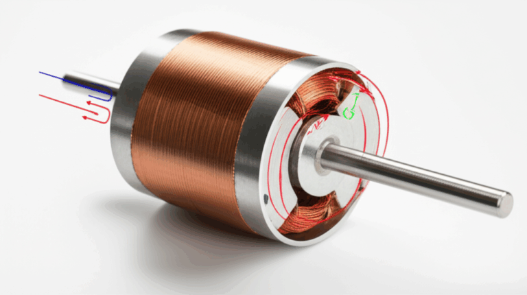
Explain: Under the hood, motor laminations drive efficiency and thermal headroom. Laminations aren’t just “stacked steel.” They’re engineered layers of insulated electrical steel that break up eddy currents and reduce iron loss. Thinner laminations with the right coating mean less heat and more torque for the same current. That gives the controller margin to survive start-up surges and sudden friction spikes from an unlubricated deck.
Guide: You’ll pick the lamination material and thickness based on your speed range, PWM frequency, target efficiency, and cost. You’ll also pick a manufacturing route. Stamping makes sense for volume. Laser cutting shines in prototyping and complex shapes. Bonding improves stack rigidity and reduces noise. Interlocking wins for speed and cost when geometry allows.
Empower: We’ll give you a short list of decisions to make and the tests to require from suppliers. You’ll see how each choice ripples through torque, temperature rise, controller stress, and service life. You’ll leave with a practical spec you can stand behind.
Core Losses 101: Eddy Currents, Hysteresis, and Switching Effects
Let’s strip it down to the basics.
- Eddy currents: Think of eddy currents like tiny whirlpools in a river. A changing magnetic field induces circulating currents in the core. Those loops waste power as heat. Thin, insulated laminations cut the whirlpools into little eddies that dissipate less energy.
- Hysteresis loss: The steel’s magnetic domains flip with each field reversal. That takes energy, and the area of the “loop” on the B-H curve is the cost. Lower coercivity steel reduces that loss.
- Additional switching effects: Modern treadmill motor controllers use PWM to modulate voltage. That injects higher frequency components into the magnetic field. Higher frequency means steeper eddy current penalties unless you design for it.
What helps
- Thinner laminations reduce eddy current loss. As frequency rises, thickness matters more.
- Lower-loss grades of non-oriented electrical steel reduce both hysteresis and eddy losses.
- The insulation coating between laminations must perform. Poor coating equals higher interlaminar conductivity and more eddy loss.
- Stress hurts you. Work hardening from stamping or heat-affected zones from laser cutting raise losses. Proper heat treatment and process control recover performance.
A quick analogy: Magnetic permeability is the steel’s “thirst” for flux lines. Picture a sponge that soaks up water easily. You want a sponge that soaks up flux without squeezing too hard and without leaking too much “heat” in the process.
The Material Playbook: Silicon Steels, Cobalt Alloys, and What Works Where
You have options. Each carries its own balance of performance, cost, and manufacturability.
- Non-oriented silicon steels (NOES): Your general-purpose workhorse for motors. These grades maintain consistent magnetic properties in all directions of the sheet. They offer a good balance of cost and loss. Commonly used thicknesses range from roughly 0.35 mm to 0.50 mm for mainstream machines. You can go thinner for higher frequency or stringent efficiency targets.
- Grain-oriented silicon steels (GOES): Designed for transformers where the flux runs along the rolling direction. Motors experience rotating fields. GOES rarely fits motor stators or rotors. Keep GOES for transformer lamination cores.
- High silicon content steels: As silicon content rises, eddy current loss decreases due to higher electrical resistivity. Permeability can drop. Mechanical brittleness can increase. Balance these effects for your geometry and stamping tolerances.
- Cobalt iron alloys: When you need high saturation flux density and lower losses at higher frequencies, cobalt-based alloys shine. They cost more. They reward you with better power density in demanding applications like aerospace or ultra-compact drives. For treadmills, you rarely need cobalt. If you push extreme duty cycles in a compact footprint, it can pay off.
- Amorphous and nanocrystalline alloys: Fantastic at cutting core losses at very high frequencies. Cost and manufacturability constraints often rule them out for mainstream traction or treadmill motors.
Coatings matter
- Inorganic phosphate coatings and organic-insulating coatings create high-resistance interfaces. They limit eddy current loops. Ask for coating class, withstand temperature, and adhesion data. Verify that the coating resists your varnish or bonding process. Coating breakdown during lamination bonding can spike loss.
Picking thickness
- Rule of thumb. As your electrical frequency increases, your lamination thickness should decrease. Fitness motors use PWM. Even if the fundamental mechanical frequency sits low, harmonic content reaches into the tens of kilohertz. Thinner laminations help the stator and rotor handle those harmonics with less heat.
Manufacturing and Assembly: Stamping vs Laser Cutting, Interlocking vs Bonding
You control loss and noise not only with material. Process makes or breaks your design.
Stamping
- Pros: Fast, cost-effective for volume, repeatable. Allows progressive dies for complex geometries. Compatible with interlocking features that speed stacking.
- Cons: Punching induces residual stress and burr. Stress raises hysteresis loss. Burrs affect stacking factor and can cut insulation. Use sharp tools, controlled clearance, and deburr where needed. Ask for post-process anneal if your application is loss sensitive.
Laser cutting
- Pros: Ideal for prototypes and low volumes. Perfect for quick design turns and complex shapes.
- Cons: The heat-affected zone raises loss unless you anneal. Cut speed and assist gas choices matter. You trade piece part cost for agility.
Waterjet and wire-EDM
- Pros: No thermal damage. Clean edges. Great when you cannot tolerate HAZ.
- Cons: Slower. Higher cost per piece. Better suited to prototyping and small runs.
Stacking and joining
- Interlocking laminations: Think LEGO. Tabs and windows snap to lock. It builds a rigid core fast with no welding. Good for volume and cost control. Verify noise and vibration targets since interlocks can rattle if tolerances drift.
- Bonding: Adhesive bonding or backlack coatings create a solid, quiet stack with high stacking factor. Great for acoustics and for minimizing circulating currents between laminations. Process control is critical. Cure profiles must match coating specs.
- Welding: Spot or seam welding delivers robust stacks. Heat can degrade local magnetic properties. Limit weld area. Validate post-weld core loss.
- Riveting or mechanical clamping: Simple and robust. Can add mass and local mechanical stress points. Use with care on high-speed rotors.
Skew and slot geometry
- Rotor skew reduces cogging torque and acoustic noise. It also changes the effective back EMF and torque ripple. Coordinate skew angle with slot count and pole count.
- Tooth tip design and slot opening shape influence harmonic content and iron loss. Work with your EM simulation team for an optimal profile.
Need a refresher on the building blocks of a motor core stack? See how the quality of the electrical steel laminations directly sets the baseline for performance.
Best Fit by Application: Home vs Commercial Treadmills, DC vs BLDC vs AC
Treadmill motors fall into a few camps. Each places different stress on the laminations and the controller.
Permanent magnet DC (brushed) motors
- Common in home treadmills. The armature carries the laminations. The stator uses permanent magnets and a back iron. PWM drives modulate armature voltage. Brushes and commutator add their own maintenance story.
- Lamination implications: Armature laminations see a high effective electrical frequency due to commutation and PWM. Thin laminations reduce eddy current loss in the armature teeth and yoke. Better material grades cut heat that would otherwise burn brushes faster.
Brushless DC (BLDC) motors
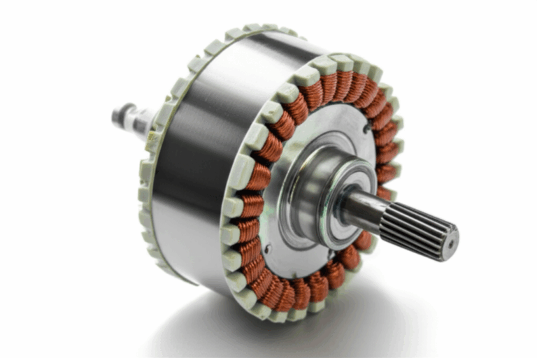
- Growing in higher-end or commercial units. The stator is laminated. The rotor carries permanent magnets and often a laminated back iron. Control uses electronic commutation. Efficiency improves. Acoustic noise drops. Maintenance improves since you lose brushes.
- Lamination implications: The stator needs high-quality laminations with tight tolerance on slot geometry to control torque ripple. Skew and careful tooth design reduce cogging. Thinner laminations help with PWM harmonics from the inverter.
AC induction motors
- Common in commercial treadmills. Rugged and long-lived. The stator is laminated steel. The rotor often uses a die-cast aluminum cage with a laminated stack.
- Lamination implications: Material choice and thickness set baseline efficiency and thermal performance across continuous duty cycles.
Matching motor type to duty
- Home users stop and start more. They run slower speeds and rely on lubrication. Deck friction can swing widely. You need torque margin and thermal margin. Better laminations lower losses and protect the controller from repeated current spikes.
- Commercial gyms want 24/7 reliability. They demand quiet operation, low heat, and strong efficiency. Premium lamination grades reduce HVAC load and extend electronics life.
If you work on BLDC variants, it helps to understand how stator design choices play with lamination quality. For deeper context, see this overview of a stator core lamination. Rotors matter too when you carry magnets or cages on stacked steel. Here’s a look at rotor core lamination.
Field Symptoms to Design Links: Belt Stuck, Motor Hums, Overheating, Trips
This is where the rubber meets the road. Or the belt meets the deck. We map common field symptoms to engineering levers you control. You’ll see many phrases users and techs search for. We use them to anchor real design decisions.
Symptom: The treadmill belt won’t move. The motor hums but the belt won’t move. The belt drags or feels stuck.
- Field causes: Lack of treadmill deck lubrication, over-tightened walking belt, drive belt slipping, worn roller bearings, debris under the belt or in the rollers, misalignment, or a seized roller.
- Design links:
- Torque margin: Undersized motors run out of starting torque when friction spikes from poor lubrication. Reduce core loss so more current translates to torque rather than heat. Thinner laminations and better steel grades help.
- Temperature rise: High iron loss elevates winding temperatures. Wires heat, resistance climbs, torque per amp falls. Better laminations protect torque under stress.
- PWM switching loss: Poor lamination selection raises eddy currents at high frequency. That steals torque during starts when you need it most.
Considerations:
- Spec a lubrication guide in the manual. You cannot design out a dry deck entirely, yet you can survive it longer with margin.
- Validate belt tension limits in testing so users cannot overtighten easily.
- Add current limits and torque limit logic in the motor controller so you avoid stall burnouts.
Symptom: The motor hums but no movement. There is a burning smell. The treadmill circuit breaker trips.
- Field causes: Shorted motor control board, shorted motor winding, bad motor capacitor in AC designs, locked roller, extreme belt friction, or a drive belt jam. In brushed DC motors, worn motor brushes or carbon deposits cause arcing and intermittent operation.
- Design links:
- Core loss and thermal headroom: Lower iron loss reduces heat rise and extends controller lifetime. Less heat means less stress on capacitors and the MCB. Cooler magnets retain flux better over time. That stabilizes torque constant and starting behavior.
- Stator and rotor profiles: Smooth slot designs and skew reduce torque ripple. Lower ripple reduces peak currents that can trip the controller on hard starts.
- Insulation coating quality: Good interlaminar insulation prevents hot spots from circulating eddy currents between laminations.
Symptom: Belt slipping and sticking under load. Speed surging. Inconsistent speed at low RPM.
- Field causes: Misaligned walking belt, poor tracking, worn drive belt, dirty or worn front roller, or degraded bearings. On the electrical side, you might see ripple from the MCB, poor sensing from a speed sensor, or unstable control loops.
- Design links:
- Low cogging torque: Use skew and refined stator tooth tips to reduce ripple and stick-slip behavior at low speed. That helps the controller regulate speed under varying friction.
- Lower loss under PWM: Lunging can show up at low speeds with high PWM duty swings if the core heats up quickly. Reduce eddy loss with thinner laminations for stability.
Symptom: Treadmill motor overheating. Automatic shutdown. Burning smell.
- Field causes: Blocked motor cooling fan, clogged motor housing with dust, poor airflow around the frame, excessive belt friction from lack of lubrication, or over-tightened belt tensioner. Electrical causes include high core loss due to poor lamination selection or stress damage during manufacturing.
- Design links:
- Choose low-loss steel and tight process control. Require core loss testing on samples to the IEC 60404 series or equivalent methods. Ask for data at your operating induction and frequency.
- Enforce anneal after laser cutting. Specify maximum burr height on stamped parts. Both actions lower hysteresis and eddy losses.
- Design for airflow around the motor housing. High temperature eats winding insulation and the motor control board.
Symptom: Safety key not working. Error codes like E1 or E2. Motor doesn’t start.
- Field causes: Console or sensor issues, wiring harness problems, damaged power cord, faulty controller board fuse, or faulty MCB.
- Design links:
- Thermal derating: A hot environment is hard on electronics. Lower motor losses reduce heat inside the motor cavity and near the MCB. Less heat equals better reliability for the control unit.
Symptom: No sound and no movement. Dead motor.
- Field causes: Blown MCB, bad controller board fuse, open circuit in motor windings, or a defective motor capacitor in AC designs.
- Design links:
- Protect the controller with a motor that runs cooler and draws less current for the same torque. Lower core losses and well-designed slot geometry keep RMS current low under load.
Common field terms you’ll hear and how they fit your design checklist
- Treadmill belt dragging, belt binding, belt stiff, belt friction, or belt sticking: Size torque margin and reduce iron loss. Validate with extreme friction tests on a dry deck board and with misaligned belt guides.
- Drive system issues: Drive belt replacement, front roller and rear roller checks, motor pulley alignment, roller bearings. Keep rotor balance tight. Lower motor vibration extends bearing life in the rollers.
- Controller and motor diagnostics: Motor brushes wear, carbon deposits, multimeter tests, motor capacitor checks, controller board inspection for scorch marks. A cooler motor reduces wear on brushes in DC designs. It also eases life for power semiconductors on the MCB.
- Over-current, trips, or overload protection: Lower core loss equals less heat. That gives you headroom to tolerate a sudden belt jam from debris without immediate shutdown.
- Noise and hum: Torque ripple and magnetostriction show up as noise. Better lamination grades and skew lower both. Bonded stacks also help.
Tie it back to procurement. When you hear “DIY treadmill motor fix” or “treadmill repair tutorial,” remember that design can avoid a large chunk of these calls. You are buying headroom with lamination choices. Fewer hums. Fewer trips. Fewer calls that start with “treadmill motor makes noise but no movement.”
Cost, Tolerances, and QA: What Procurement Should Require
You do not need a gold-plated solution. You need the right tolerances and reliable data. Here is the short list we ask procurement to lock in.
Material and coating
- Specify NOES grade and thickness with target core loss and permeability at your intended frequency and induction. Ask for mill certificates.
- Define the insulation coating class with max operating temperature, chemical compatibility, and interlaminar resistance targets. Require coating adhesion tests after your lamination bonding cycle.
Geometry and tolerance
- Tolerance the slot opening and tooth tip features tightly. Torque ripple is sensitive here.
- Limit burr height. Burr increases stacking thickness and can cut insulation. It also creates mechanical interference that leads to noise.
- Control rotor skew geometry and alignment. Verify skew angle across the stack.
Manufacturing quality
- If stamped, define die maintenance intervals and edge quality metrics. Consider post-stamp anneal when losses are critical.
- If laser cut, require stress relief anneal with defined temperature and time. Verify restoration of magnetic properties.
- Define stacking method: interlock, bonding, welding, or a hybrid. Each method needs acceptance criteria for stack height, straightness, lamination shift, and vibration.
- Require stacking factor data. You want to know how much of the physical stack height is steel versus insulation and air. That affects magnetic design.
Validation and test
- Require core loss testing on witness stacks or Epstein strips at operating frequencies. Reference recognized test methods in the IEC 60404 series.
- Ask for noise and vibration data if acoustics matter. Include torque ripple data from dynamometer tests.
- Verify temperature rise at duty points relevant to treadmill use. Include start-stop cycles and high friction conditions that simulate poor deck lubrication.
Supplier capability
- Confirm they can do both rapid prototyping and production scaling. You will iterate geometry early and build volume later.
- Ensure traceability for material heats and lots. Fitness OEMs face warranty claims. You want traceable data for any investigation.
Ready to frame a vendor discussion at the component level rather than part numbers only? Use this umbrella concept as you engage with suppliers of motor core laminations.
“Which Application Is This For?” Home vs Commercial, Start-Stop vs Continuous, Size-Constrained vs Cost-Driven
You do not need the same lamination stack for every treadmill.
- Home treadmills with frequent start-stop: Emphasize low core loss and thin laminations to keep temperatures stable under PWM-rich operation. Skew and refined slots to reduce torque ripple. Use bonding if you chase low noise and don’t want interlock click.
- Commercial treadmills with continuous duty: Prioritize efficiency and temperature rise under steady loads. NOES in a low-loss grade makes sense. Don’t over-spec thickness if the frequency content is modest. Interlocks save cost and time.
- Compact high-power units: If you must shrink the motor and keep performance, move toward thinner laminations and possibly higher performance alloys. Validate cost impact carefully. They can blow budgets fast.
- BLDC upgrades: Focus on stator quality. Bonded stacks often win on acoustics. Rotor back iron needs material choice that supports strong magnet flux without early saturation. Watch for demagnetization risks at high temperatures and low speed high torque.
- AC induction solutions: Keep an eye on rotor bar design and stator slot harmonics. You’ll get big wins from stamping quality and post-process anneal.
Ask one question early. What hurts us more in the field, heat or noise. If heat kills controllers and brushes, prioritize low loss. If noise drives returns, pursue skew and bonding.
How Lamination Choices Protect the Controller and Power Electronics
Most treadmill service calls blend mechanical and electrical triggers. Still, many “treadmill motor controller board repair” or “faulty MCB” cases stem from thermal stress. Lower motor iron loss helps the controller in three ways.
- Less average heat around the MCB. Electronic components live longer. Capacitors and power semiconductors see lower junction temperatures.
- Lower RMS current for the same torque. That reduces I²R losses in the motor and the controller’s MOSFETs or IGBTs.
- Smoother torque. Reduced ripple means fewer current spikes. Current spikes often trigger trips in overload protection. They also stress solder joints and connectors.
Don’t forget safety. A cooler motor is less likely to emit a burning smell or trip a circuit breaker during a tough start when the belt is dry or the deck is rough.
Practical Treadmill-Specific Design Checklist
Even if you never turn a wrench, you still need to anchor your design against the common field issues techs see during treadmill motor troubleshooting. Here’s the shortlist framed for design.
Torque and thermal margin
- Design for start-up torque with worst-case friction. That includes belt misalignment, lack of deck lubrication, and heavy users.
- Tune PWM strategy to limit high-frequency loss while delivering smooth low-speed control. Coordinate controller PWM frequency with your lamination thickness.
Core and stack
- Pick lamination thickness to match frequency content. Thinner when PWM frequency rises. Favor low-loss NOES grades for most treadmill applications.
- Specify coating and verify interlaminar resistance after your stacking method.
- Choose stacking method based on cost and acoustics. Interlocking for cost and speed. Bonding for noise and electrical isolation.
Geometry
- Optimize tooth tip and slot shape to minimize torque ripple and acoustic noise.
- Add rotor skew if cogging is an issue. Do not overdo skew since it can reduce torque.
Quality and validation
- Limit burrs and recover stress with post-process anneal where needed.
- Validate core loss on samples. Correlate to temperature rise in full motor tests.
- Test for noise. Users judge quality by sound and feel.
System integration
- Coordinate with the motor control board team. Align PWM and current limits with motor electromagnetics. Protect the controller with thermal headroom.
- Validate roller and belt system component quality. A perfect motor cannot save poor roller bearings.
Procurement
- Lock in material grade, thickness, coating, tolerances, and process controls in the PO. Demand core loss data and stacking factor reports.
- Pick suppliers with both prototyping and production chops. You will need both at different stages.
Frequently Observed Field Terms and How They Translate to Design Assurance
You’ll hear or read many of these during service calls or in online searches. Use them to shape acceptance tests.
- Treadmill motor overheating causes: Validate core loss and thermal design. Test with blocked airflow and high ambient temperature.
- Treadmill motor output and current draw: Require dynamometer tests across the speed range. Log RMS current vs torque. Watch for ripple under PWM.
- Treadmill motor voltage test and winding test: Bake these into end-of-line tests. A healthy motor out of the box makes field failures less likely.
- Treadmill motor fuse location and overload protection: Design the motor so that protective devices don’t trip under normal allowable friction spikes. Margin saves your reputation.
- Treadmill motor brushes wear and carbon brushes: Lower heat extends brush life. Smooth torque reduces arcing.
- Treadmill motor cooling fan: Guard against dust and debris with proper shrouds and vents. Lower internal loss reduces dependence on airflow.
- Treadmill belt alignment issues and belt tension adjustment: Verify design allows proper tracking and tension without overloading the motor. Avoid designs that let users crank the tensioner far past spec.
- Treadmill rollers seized and roller bearings: Specify roller bearing quality. Vibration from the motor can shorten bearing life. Balance the rotor well and hold tight tolerances on the motor pulley.
- Motor control board error codes and motor control unit: Keep the motor cool and predictable so the controller doesn’t live on the edge of its protection curves.
- Preventative maintenance: Lower heat and smoother torque reduce maintenance frequency. That helps your total cost of ownership pitch.
For engineers working on BLDC conversions or variants, you might also find value in a quick overview of a rotor core lamination stack since it directly influences magnetic back iron saturation and NVH.
When Laser Cutting or Bonding Is the Right Call
Honesty builds trust. Laser and bonding are not magic bullets. They are tools you deploy strategically.
Laser cutting
- Best for prototypes, rapid iterations, and complex geometries with short lead times.
- Not ideal for high-volume without post-cut anneal. The HAZ pushes losses up. You can fix it with a well-controlled thermal cycle.
- Use laser for early development. Switch to stamping when you tool up.
Bonding
- Delivers quiet stacks with high stacking factor and minimal interlaminar currents.
- Demands strong process control on adhesive or backlack cure. Overbake can harm coating. Underbake can cause delamination.
- Worth it when acoustic noise and NVH drive returns or reviews. If a click or whine causes users to think “motor makes noise but no movement” you lose trust.
Interlocks
- You win on speed and cost. Tune tab geometry to kill rattle. Validate under vibration.
- Good for home treadmill volumes and many commercial builds.
Stamping
- Your mainstay for volume and cost control. Maintain die sharpness and burr control. Plan die maintenance in the PO.
If you are scoping a BLDC stator with fine slot geometries, you may need a lamination partner who can run tight tolerances and clean edges consistently. That starts with the base material quality in electrical steel laminations.
The Business Case: Efficiency, Warranty, and Reputation
Let’s cut to brass tacks. Why should procurement pay for better laminations.
- Lower operating temperature prolongs the life of windings, bearings, and motor control boards. That means fewer warranty claims.
- Higher efficiency cuts energy cost for commercial gyms. Your customers feel that on their utility bills.
- Smoother starts and low-speed control reduce user complaints about belt sticking or surging. Returns drop when the product “feels” premium.
- Better acoustics win reviews. In home use, noise kills. Bonded stators and skewed rotors reduce the whine and buzz that users hate.
You do not need the top shelf on every model. Segment your portfolio. Offer a premium motor for the flagship and a cost-optimized version for entry models. Tie lamination specs to that segmentation.
Your Engineering Takeaway and Next Steps
Key points to remember
- Laminations set your loss floor. They dictate how much heat you make before you ever push copper.
- Thinner laminations and better steel grades pay off when PWM harmonics rise or when low-speed smoothness matters.
- Process control matters. Stamping burr, laser HAZ, and coating damage can erase the gains of a good material choice.
- Stack construction changes acoustics and durability. Interlocks are fast and cost effective. Bonding is quiet and rigid.
- Tie design to field symptoms. If you see “treadmill belt dragging” or “motor hums but no movement,” first check your torque and thermal margin. Then sharpen the lamination and stacking specs.
- Procurement must demand data: core loss at relevant induction and frequency, stacking factor, burr limits, anneal requirements, and traceability.
Actionable next steps
- Define your duty cycle and PWM strategy. Share the frequency content with your lamination supplier.
- Select a NOES grade and a target lamination thickness that balance performance and cost. Use prototypes to measure temperature rise and torque ripple.
- Pick a stacking method based on NVH goals. Use bonding for quiet operation. Use interlocks for cost and speed.
- Validate with lab tests. Run thermal tests with a dry deck and misaligned belt as worst-case. Log controller current, torque ripple, and surface temperature.
- Lock specs in the PO. Include coating class, burr height, stack straightness, and required anneal.
- Shortlist suppliers with both prototyping and production capability. You will need both.
If you want a quick orientation on how complete lamination stacks come together across rotor and stator designs, explore the breadth of electrical steel laminations. For program-level context on assembled motor stacks and options across topologies, take a look at motor core laminations. For a focused look at stationary elements, see stator core lamination. If your team is refining rotor back iron and skew schemes, review rotor core lamination.
You design motors that must survive real users and real environments. The belt will be too tight sometimes. The deck will run dry. Dust will find the motor housing. Good lamination choices do not fix a tangled toy under the belt, yet they keep your motor cooler and your controller calmer while the machine handles the abuse. That is the difference between a product that sparks panic when it hums and stalls, and one that simply pushes through then keeps running.
You now have the playbook. Use it to spec smarter laminations, ask sharper questions, and buy a little peace of mind for every service team you support.