How Does an Electric Motor Work? My Hands-On Guide to the Motor That Moves the World
Table of contents
- Introduction: The silent powerhouse of our world
- The fundamental principle: Electromagnetism in action
- Electric current and magnetic fields
- The Lorentz force and Faraday’s law
- Key components of an electric motor
- The stator
- The rotor (armature)
- Commutator and brushes
- Slip rings and electronic commutation
- The rest of the hardware that keeps things spinning
- How it works: Step-by-step
- DC motors
- AC induction motors
- Synchronous motors
- Types of electric motors at a glance
- Where motors work: Real-world applications
- Efficiency, control, and maintenance
- Why efficiency matters
- Motor control and speed
- Back EMF, torque, and noise
- Heat, reliability, and predictive maintenance
- Evolution and the future of electric motors
- Quick mental models that helped me “get it”
- Common questions I hear
- Conclusion: Powering progress, one rotation at a time
Introduction: The silent powerhouse of our world
The first time I made a motor spin, I used a battery, a magnet, two paperclips, and a crooked copper coil. It vibrated like a bee, then it turned. Not smoothly. Not silently. It was enough to hook me for life. Since then I’ve repaired fans, spec’d motors for automation projects, and dissected more than a few broken tools to see what fried.
Here’s the simple truth I learned. An electric motor converts electrical energy into mechanical energy. Electricity goes in. Spinning torque comes out. That’s it in one line. The deeper story is much more interesting. The physics is elegant. The parts are clever. The applications touch almost everything you use today.
Motors are everywhere. Phones buzz with tiny vibration motors. Washers churn. HVAC blowers keep air moving. Elevators lift. Robots weld. Electric vehicles leap off the line with quiet speed. By some estimates, motors account for 45 to 50% of global electricity use. In factories the number sits around 70%. That’s why motor efficiency, control, and design matter so much to engineers and to all of us who pay the power bill.
Let me walk you through how the magic works without the hand-waving. I’ll keep the math light. I’ll use plain English, practical examples, and a few analogies that helped me make sense of it all.
The fundamental principle: Electromagnetism in action
You don’t need a degree to grasp the big idea. Electricity and magnetism are two sides of the same coin. Run electric current through a wire and you get a magnetic field around that wire. Put that wire in a magnetic field and the current in it feels a push. That push becomes force. Force applied at a radius becomes torque. Torque turns a shaft.
Electric current and magnetic fields
In 1820 Hans Christian Ørsted discovered that an electric current deflects a compass needle. Current creates a magnetic field. That field has direction. It loops around the wire like invisible rings. Stack the wire into a coil and you concentrate the field. Add iron inside the coil and the magnetic field strengthens because the iron’s domains align with the field. That’s the basic electromagnet.
Magnetic poles work like you’d expect. Opposites attract. Like poles repel. Arrange current and magnets so that a current-carrying conductor sits in a magnetic field with the right orientation and it experiences a push.
The Lorentz force and Faraday’s law
The push I just mentioned has a name. It’s the Lorentz force. The direction follows a right-hand rule. Point your thumb along the current and your fingers along the magnetic field. Your palm pushes in the direction of the force. That force on each segment of a coil produces torque on the coil. Spin happens when the torque doesn’t cancel out over the full rotation.
There’s a second crucial piece. Motion in a magnetic field induces voltage. That’s Faraday’s law of electromagnetic induction. Motors exploit the first effect to produce motion. Generators exploit the second to produce electricity. Here’s the neat part. Every motor behaves like a generator while it spins. It generates a voltage that fights the supply called back EMF. That self-limiting effect stabilizes current and protects the motor at speed.
Put those two ideas together and you’ve got a working mental model:
- Current creates magnetic fields.
- Magnetic fields push on current-carrying conductors.
- Motion in magnetic fields induces voltage that opposes the change.
That’s a motor in three bullets.
Key components of an electric motor
Motors come in many flavors. Under the hood they share a common cast of characters. When I open a motor I’m looking for the stationary magnetic field source, the rotating current-carrying piece, and the method that feeds or switches current to keep torque in the right direction.
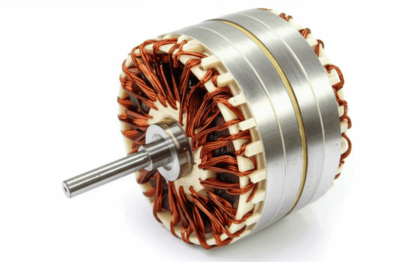
The stator
The stator is the stationary part. It either holds permanent magnets or it houses field windings that become an electromagnet when energized. In AC machines the stator typically builds the rotating magnetic field that the rotor chases.
The stator’s core is made of thin steel sheets called laminations. These laminations reduce eddy current losses in alternating fields. Without laminations the iron would heat up fast because induced currents would swirl around inside like whirlpools. If you want to dive deeper into this piece of engineering I recommend reading about stator core lamination. The quality of the steel and the geometry of the slots matter a lot for efficiency and noise.
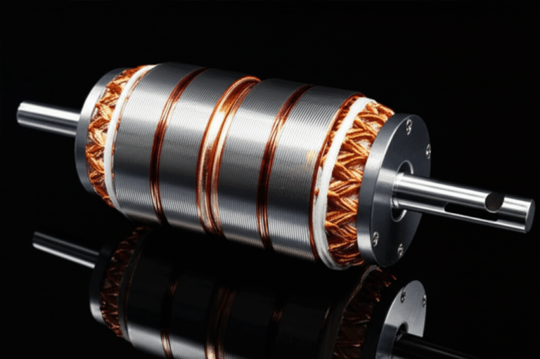
The rotor (armature)
The rotor is the rotating part. In many DC motors the rotor carries the coils that get energized. In most AC induction motors the rotor holds conductive bars shorted at both ends by rings. That squirrel-cage design is rugged and simple. In permanent magnet synchronous motors the rotor carries powerful magnets instead of windings.
Just like the stator, the rotor uses thin laminations to cut core losses as magnetic fields change with rotation. I’ve seen burned rotors where poor lamination or heat killed efficiency. If you’re curious, here’s more on rotor core lamination.
The rotor sits on a shaft supported by bearings. That shaft delivers torque to your load.
Commutator and brushes
Brushed DC motors use a commutator and brushes to flip current at the right time. The commutator is a segmented copper ring attached to the rotor. Carbon brushes press against it and feed current. As the rotor turns different segments connect and disconnect, which reverses the current in the right coils. That reversal keeps the torque pointing in a consistent direction so the rotor doesn’t stall at top dead center.
It’s clever and it works. It also wears. Brushes arc and produce dust. Commutators need maintenance. That’s why brushless designs rose to dominance in many areas.
Slip rings and electronic commutation
Some AC motors use slip rings to feed current into a wound rotor. Slip rings are continuous rings that avoid the switching segments of a commutator. They let AC flow into rotor windings, which helps with control or startup torque.
Brushless DC motors and many high-performance AC motors avoid brushes and slip rings. They rely on solid-state inverters and control algorithms to commutate electronically. That means the controller switches current among stator coils in a sequence that drags the rotor around. The rotor might carry magnets. The result is high efficiency, low maintenance, and precise control.
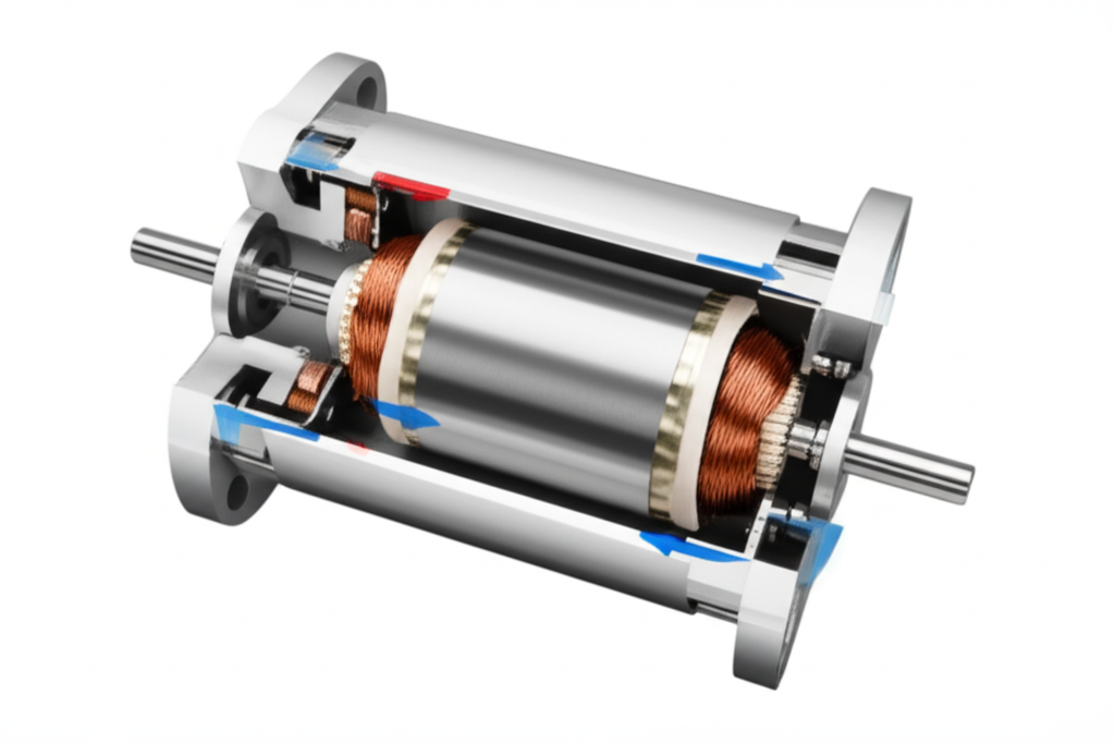
The rest of the hardware that keeps things spinning
A few more parts show up in most motors:
- Frame and end bells that hold the assembly together and protect it
- Bearings that support the shaft
- Windings of copper wire laid into slots
- A terminal box for connections
- Sensors in some motors such as Hall effect sensors for rotor position
- Cooling features and thermal sensors for safety
On the materials side, laminations for both stator and rotor matter. The go-to is silicon steel. The stack of thin sheets forms the magnetic core. If you want a broad overview start with motor core laminations then branch into specific variants like grain-oriented steel if you explore transformers.
How it works: Step-by-step
You’ll hear “DC” and “AC” a lot. That’s the supply type. Direct current has one direction. Alternating current swings direction and magnitude in a sine wave. Each type leads to different design choices.
DC motors
I started with a DC motor in school because it’s visual and intuitive. Imagine a rotor with a simple coil sitting between the north and south poles of a stator magnet.
- Step 1: Apply DC voltage. Current flows into the rotor coil through the brushes and commutator.
- Step 2: That current creates a magnetic field around the coil. The coil becomes a tiny electromagnet.
- Step 3: The stator’s magnetic poles push and pull on the rotor’s new poles. That’s the Lorentz force in action across the length of the coil. Torque appears on the shaft.
- Step 4: As the rotor approaches the point where the torque would reverse, the commutator flips which coil segments get current. The current in the active coil reverses. The torque keeps pushing the same rotational direction.
- Step 5: The cycle repeats with every half turn.
Speed rises until back EMF balances the applied voltage minus losses. That back EMF scales with speed. If you load the shaft the motor slows a bit which reduces back EMF. Current rises. Torque increases. The motor pushes back.
There are flavors:
- Series DC motor: Field and armature in series. High starting torque and speed rises with light load.
- Shunt DC motor: Field in parallel with armature. More stable speed under varying load.
- Brushless DC motor (BLDC): Permanent magnets on the rotor. Electronic commutation replaces brushes. High efficiency and long life. I like these for drones and EV auxiliaries because they pack a lot of punch in a small package.
AC induction motors
The AC induction motor powers industry. It’s reliable and cheap. No brushes. No magnets on the rotor. The physics feels almost magical the first time you see it.
- Step 1: Apply AC to the stator windings. Those windings are arranged in phases. Two-phase or three-phase being common. Three-phase creates a rotating magnetic field in space. The field spins at synchronous speed which equals 120 times the frequency divided by the number of pole pairs.
- Step 2: That rotating field sweeps across the rotor bars. According to Faraday’s law, it induces currents in the rotor. The rotor didn’t connect to the supply which is why we call it induction.
- Step 3: The induced currents create their own magnetic field. That field interacts with the stator’s rotating field.
- Step 4: The rotor experiences torque and starts spinning. It never quite catches up to the stator field. The difference in speed is called slip. Slip is essential. No slip means no relative motion which means no induction and thus no torque.
In my shop I tested a small three-phase motor with a variable frequency drive. I swept frequency from 20 Hz up to 60 Hz. The motor’s speed tracked the drive because synchronous speed scales with frequency. Slip increased with load as expected.
Single-phase induction motors need a trick to start. They use a start winding with a phase shift or a capacitor to create a temporary rotating field. Once running they can drop the start winding and keep going.
Synchronous motors
Synchronous motors lock their rotor to the stator’s rotating field. No slip in steady state. That can happen with a DC-excited rotor, a permanent magnet rotor, or with a synchronous reluctance design that uses geometry. Permanent Magnet Synchronous Motors (PMSM) show up in electric vehicles because they deliver high torque density and excellent efficiency. They also enable regenerative braking where the motor acts as a generator to feed energy back into the battery during deceleration.
Stepper motors move in precise steps rather than spin freely. The stator energizes phases in sequence to pull the rotor into discrete positions. Servos combine a motor with feedback and control to track position or speed with high accuracy.
Types of electric motors at a glance
Here’s how I categorize them when I choose a motor for a project:
- DC Motors
- Brushed DC: Simple control with voltage. Wear items from brushes.
- Brushless DC (BLDC): Permanent magnet rotor. Electronic commutation. Great efficiency and high reliability.
- AC Motors
- Induction (asynchronous): Most common industrial workhorse. Rugged and cost-effective.
- Synchronous: Locks to the rotating field. Includes PMSM and reluctance motors.
- Specialty Types
- Stepper: Precise steps for printers, CNC axes, and small robotics.
- Servo: Motor plus encoder and control loop for precision positioning.
- Universal motor: Brushed motor that runs on AC or DC. High speed and found in tools and appliances.
- Switched reluctance motor (SRM): Simple rotor, high efficiency with modern control, characteristic torque ripple.
- Linear motors: Unroll the stator and rotor to get linear motion.
Each design trades cost, control complexity, torque ripple, noise, and efficiency. Electric vehicle motors lean toward PMSM and sometimes induction. Drones love BLDC. Conveyor belts and pumps live with induction motors for decades.
Where motors work: Real-world applications
I play a game sometimes. I look around a room and count motors. In a small house I easily find twenty. Here are the big buckets:
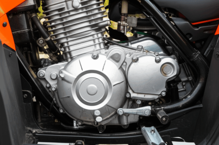
- Everyday life: Fridge compressors, washer and dryer drums, dishwashers, vacuum cleaners, stand mixers, fans, power tools, and HVAC blowers.
- Transportation: Electric vehicles, trains, e-bikes, and scooters. EVs showcase motor control and efficiency under demanding conditions.
- Industry: Pumps, compressors, conveyors, robotics, CNC machines, and industrial fans drive factories that run nonstop.
- Renewable energy: Wind turbines use the same principles in reverse to generate power. Pitch motors and yaw motors position blades and nacelles.
- Medical devices and precision equipment: Pumps, surgical tools, and imaging systems demand silent, controllable motion.
This ubiquity explains the market size. Analysts expect the global motor market to exceed 200 billion USD by the end of the decade. It also explains the push for efficiency standards because small gains scale to huge savings when you multiply by billions of machines.
Efficiency, control, and maintenance
If motors consume roughly half of global electricity then every percent of efficiency matters. Efficiency equals mechanical output power divided by electrical input power. Losses sneak in through several doors.
- Copper losses: I squared R losses in the windings
- Core losses: Hysteresis and eddy currents in the steel
- Mechanical losses: Bearing friction and air drag
- Stray load losses: Harmonics and leakage
Why efficiency matters
Premium efficiency classes like IE3 and IE4 squeeze losses down. That can mean better steel, improved lamination thickness, optimized slot geometry, tighter manufacturing, and smarter cooling. BLDC and PMSM designs push motor efficiency over 95% in top applications. You feel the difference as less heat and lower power draw for the same work.
Laminations make a big dent in core losses. The thin insulated sheets break up eddy currents so they can’t swirl freely. Material quality matters here. If you want to explore the materials side, this overview of electrical steel laminations explains why silicon content and lamination thickness change performance.
Motor control and speed
I grew up thinking motors just plugged into the wall. Then I met variable frequency drives (VFDs) and motor controllers. Control changes the game.
- VFDs: They adjust AC frequency and voltage to change the speed of induction motors. You get soft starts, precise speed control, and energy savings in fan and pump applications because power often scales with the cube of speed.
- BLDC and PMSM controllers: They run field-oriented control or other strategies. They sense rotor position with Hall sensors or calculate it sensorlessly from back EMF. The controller modulates current to match the required torque and speed.
- DC motor drivers: Simple PWM voltage control can set speed. Closed-loop control improves stability under load.
Speed control lets you match motor output to demand. That cuts energy use and improves process quality. I used a VFD on a conveyor upgrade and saw smoother starts that saved belts. Energy usage dropped because we could run at the optimal speed instead of full tilt.
Back EMF, torque, and noise
A few concepts tie directly to what you feel and hear:
- Back EMF: The motor generates a voltage that opposes the supply as it spins. It’s proportional to speed. That effect caps current at high speed which stabilizes operation.
- Torque: Motor torque comes from the cross product of magnetic flux and current. Increase flux or current and torque rises until you hit saturation or thermal limits.
- Noise and vibration: Magnetic forces can ripple at switching or slot frequencies. Mechanical imbalance adds its own buzz. Stator tooth geometry and winding layout help reduce acoustic noise. So does better control that softens torque ripple.
Heat, reliability, and predictive maintenance
Heat kills motors. High temperature degrades winding insulation and accelerates bearing wear. Good thermal design, proper ventilation, and sensible loading extend life. Motors in industry can run 15 to 20 years or more with good care. I’ve seen elevator motors run for decades because maintenance teams respect load limits and keep bearings healthy.
Here’s what I watch:
- Temperature rise against nameplate limits
- Bearing noise and vibration spectra
- Insulation resistance and polarization index
- Current asymmetry and harmonic content
- Cleanliness of cooling paths
Smart drives make this easier. Modern controllers log data and flag unusual trends. Predictive maintenance reduces downtime because you don’t wait for a bearing to seize or a winding to short.
Evolution and the future of electric motors
Two themes shape the future. Better materials and smarter control.
Materials first. Electrical steel keeps improving. Lamination geometry gets more refined. Permanent magnets get stronger with better thermal stability. Manufacturing tightens up. I keep an eye on topics like advanced alloys, powder metallurgy, and novel rotor topologies that cut rare-earth use without killing performance.
Control next. Power electronics keep getting more efficient and compact. Algorithms get better at squeezing torque while keeping noise down. Sensorless control improves, which cuts cost and increases reliability. IoT features bring motors into the larger system. You can monitor fleets and schedule service based on real data.
Electric vehicles push the envelope. They demand high torque density, excellent efficiency over wide speed ranges, and reliable thermal management. Engineers combine PMSM, induction, or switched reluctance technology with clever cooling and tight packaging. Regenerative braking captures energy you used to waste as heat. That matters for range.
And yes, researchers explore superconductivity and magnetostrictive materials for niche uses. Those ideas show promise in special applications where weight or specific performance metrics rule the day. They won’t replace mainstream designs soon. They push the frontier which eventually pulls everyday designs forward.
One detail that often gets overlooked is the lamination stack itself. The stack design and manufacturing quality influence loss, vibration, and noise. I’ve specified different lamination vendors for prototypes because tiny differences in steel and stamping made measurable differences in performance.
If you want a more concrete look at the building blocks behind all of this, take a peek at stator core lamination and rotor core lamination. Those two pages show how the laminated cores actually come together. For a broader picture, the overview on motor core laminations ties it back to whole machines.
Quick mental models that helped me “get it”
- Think of the stator field as a moving hand that keeps pushing the rotor around. If the hand stops moving then the rotor stops because the push disappears.
- Picture the rotor in an induction motor like a metal squirrel cage. The stator’s rotating field induces currents in the bars. Those currents create their own field which tries to align with the stator’s field. The rotor chases the moving target and keeps missing by a little bit. That miss is slip.
- Back EMF acts like a self-control mechanism. As the motor speeds up, its “internal generator” produces a voltage that cancels more of the supply. Current drops. Heating falls. The motor finds a balance point for a given load.
Common questions I hear
- Why do motors spin at all? The Lorentz force pushes on each segment of a current-carrying coil in a magnetic field. That push creates torque. A commutator or controller keeps the torque direction consistent as the rotor turns.
- What’s the difference between DC and AC motors? DC motors feed current directly into rotor windings or use magnets with electronic commutation. AC induction motors rely on a rotating stator field that induces rotor currents without wires. Synchronous motors lock the rotor field to the stator field and require excitation or magnets.
- What sets motor speed? For an induction motor, synchronous speed is 120 times the supply frequency divided by the number of poles. Actual speed sits a bit below due to slip. For DC and BLDC motors, controllers set speed by modulating voltage or electrical frequency.
- How do magnets help? Permanent magnets on the rotor provide a strong, fixed magnetic field. That raises torque density and efficiency because you don’t need to feed current into the rotor to create flux.
- Why do engineers love laminations? Alternating magnetic fields induce eddy currents in solid steel which waste energy as heat. Laminations break up those currents. Thinner laminations with good insulation reduce losses further. If you’re curious about the steel itself, this guide to electrical steel laminations explains the common alloys and why silicon improves performance.
- Are motors good for the environment? They can be. High-efficiency designs cut energy use which reduces emissions when the grid isn’t fully clean. Electric vehicles replace tailpipe emissions with power plant emissions that get cleaner over time.
Conclusion: Powering progress, one rotation at a time
I built my first motor with shaky hands and a lot of curiosity. The physics that moved that little copper loop also moves trains, machines, and cars. Electric motors are the silent muscles of modern life. They turn electrical energy into mechanical work with a level of efficiency that still amazes me.
Here’s what matters when you zoom out:
- Electromagnetism sits at the heart of every motor. Current creates magnetic fields. Those fields push on current-carrying conductors to create torque.
- The stator sets the stage. The rotor takes the push and delivers torque through the shaft.
- DC, AC induction, and synchronous designs all use the same physics with different tricks for feeding and timing current.
- Efficiency isn’t a buzzword. It’s the difference between a cool-running, long-lived motor and a hot, wasteful one. Laminations, materials, and control turn the dial.
- Smarter control and better materials will keep driving improvements. EVs and industrial automation push the frontier which improves everything else downstream.
If you only remember one thing, remember this. Motors work because electricity and magnetism play together in a way that turns invisible fields into real force. Flip the switch and that invisible dance starts. The rest is clever engineering and a lot of thoughtful metal.
Internal links used in this article: