How Does an Electric Motor Work? A Simple Guide to the Science Behind Motion
Table of Contents
2.1 Magnetic fields and where they come from
2.2 Current and fields: the link that makes motors possible
2.3 The Lorentz force: the push that creates torque
3.1 Stator and rotor
3.2 Coils, windings, and magnetic flux
3.3 Commutator and brushes in DC motors
3.4 Bearings, shaft, insulation, and cooling
4.1 Initial setup and current flow
4.2 Field interaction and torque generation
4.3 The commutator’s job: continuous rotation
4.4 Energy conversion in action
5.1 The big difference between AC and DC motors
5.2 Induction motors: the workhorse of industry
5.3 Synchronous motors: locked in step
5.4 Single-phase, three-phase, and capacitors
6.1 Brushed DC motors
6.2 Brushless DC (BLDC) motors
6.3 Stepper motors
6.4 Servo motors
6.5 Universal motors
7.1 Voltage, current, and torque-speed curves
7.2 Reversing direction
7.3 VFDs and motor drives
8.1 Everyday devices at home
8.2 Transportation and EVs
8.3 Industrial and HVAC systems
9.1 Why efficiency matters
9.2 IE efficiency classes and what they mean
9.3 Materials, laminations, and power density
9.4 Noise, vibration, and reliability
1. Introduction: Why Motors Hooked Me
The first time I made a motor spin I used a battery, a magnet, and a bent paperclip. The setup looked like a science fair gone wrong. The moment the loop of wire started to twitch then turn I got hooked. Ever since I’ve been tearing down fans, opening washing machine motors, and peeking under the hood of electric vehicles to understand what’s going on.
Here’s the short version I wish someone had told me early. An electric motor converts electrical energy into mechanical energy. It does that by using electromagnetism to create a torque that makes a rotor spin. You supply current. The motor brings magnets and coils to the party. The result is motion.
In this guide I’ll walk you through the basic motor principle, the key components, DC and AC motor operation, and the differences between motor types. I’ll keep it simple. I’ll also share the little tricks that helped me remember how it all fits together.
2. The Core Idea: Electromagnetism Turns Electricity into Motion
If you only remember one thing take this. Electric current and magnetic fields interact in a way that produces force. Motors exploit that force in a circle.
2.1 Magnetic fields and where they come from
You can get a magnetic field from two sources.
- Permanent magnets: Think neodymium magnets that stick to your fridge with gusto. They provide a steady field with north and south poles.
- Electromagnets: Run current through a coil of wire and you create a magnetic field around it. Add an iron core and you beef up that field. This is how a motor’s windings work.
When we talk motor physics you’ll hear “magnetic flux.” That’s just a fancy term for how much magnetic field passes through an area. More turns in a coil and better core materials increase flux. Flux matters because it sets the stage for strong torque.
2.2 Current and fields: the link that makes motors possible
A Danish physicist named Oersted noticed that current in a wire deflects a compass needle. That shocker revealed the link. Current produces a magnetic field.
The right-hand rule helps you see the direction. Point your thumb in the direction of conventional current. Your curled fingers show the direction of the magnetic field around the wire. Later I learned a second right-hand rule for the direction of force on a current-carrying conductor inside a magnetic field. Thumb for current. Fingers for magnetic field. Palm shows the force.
2.3 The Lorentz force: the push that creates torque
At the heart of every motor sits the Lorentz force. Put a conductor with current inside a magnetic field and it feels a sideways push. That push on opposite sides of a loop becomes a torque. Stack many loops and you get a strong rotational force.
Faraday took this further. Change in magnetic flux induces a voltage. We call it electromotive force or EMF. Motors feel this as “back EMF” which opposes the applied voltage as speed rises. It’s a self-regulating effect that keeps a motor from drawing infinite current at high speed.
3. Anatomy of an Electric Motor: Parts and Purpose
When I teach “what is an electric motor” I start with a simple diagram. Then I point to each part and explain the job.
3.1 Stator and rotor
- Stator: The stationary part of the motor. It holds coils or permanent magnets that create the main magnetic field. In most AC motors the stator windings generate a rotating magnetic field. The quality of the stator core lamination matters because it reduces eddy current losses and improves efficiency.
- Rotor: The rotating part. In DC motors it holds the armature windings. In induction motors it’s a squirrel cage or wound rotor. The rotor’s steel stack uses laminations to limit losses which boosts performance. You’ll see designs that rely on a robust rotor core lamination to hit the right torque-speed curve.
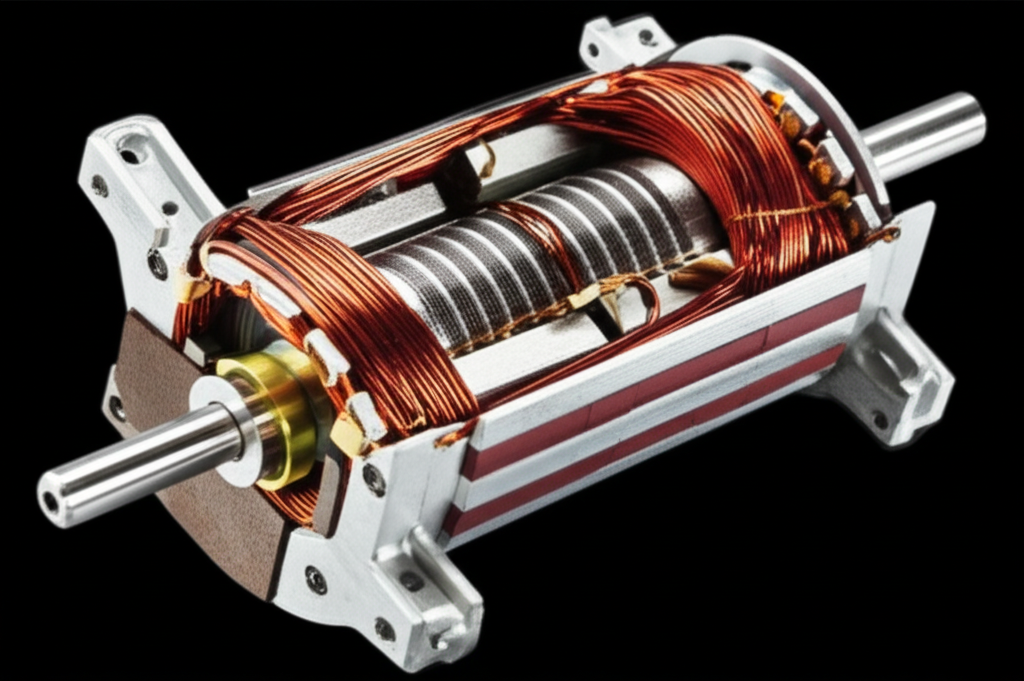
3.2 Coils, windings, and magnetic flux
Windings are insulated copper wires wrapped into coils. When current flows these coils behave like electromagnets. The core material inside those coils shapes the magnetic flux. Manufacturers use stacked sheets of thin electrical steel for the core because solid steel would waste energy as heat. Laminations slash eddy currents which keeps the motor efficient and cool. If you’re curious about the material itself you’ll run into electrical steel laminations a lot in motor and transformer cores.
3.3 Commutator and brushes in DC motors
Brushed DC motors need two extra parts.
- Commutator: A segmented copper ring attached to the rotor. As the rotor spins it swaps which coil segment each brush touches. That reverses current in the armature windings at just the right time which keeps the torque pointing forward.
- Brushes: Stationary carbon contacts that press on the commutator. They deliver current into the spinning armature. Brushes wear over time so brushed motors need maintenance.
3.4 Bearings, shaft, insulation, and cooling
- Bearings support the rotor and reduce friction. They can fail if you skip lubrication or overload the motor.
- The shaft connects the rotor to your load. Gears, belts, and couplings mount here.
- Insulation protects windings from short circuits and heat. Insulation class tells you how hot the motor can run safely.
- Cooling keeps a motor alive. You’ll see fans on the shaft, external blowers, or liquid cooling in high power density machines. Some motors rely on the load’s airflow like a fan motor inside an HVAC system.
Capacitors show up in single-phase AC motors to create a phase shift for starting torque. You’ll see “start” and “run” capacitors depending on the design.
4. How a DC Motor Works: A Step-by-Step Walkthrough
A brushed DC motor offers the cleanest window into the basic motor principle. Here’s the sequence I keep in my head.
4.1 Initial setup and current flow
You apply voltage to the terminals. Current flows from the power source through the brushes into the commutator segments and into the armature windings. The armature windings generate a magnetic field.
4.2 Field interaction and torque generation
The armature’s magnetic field interacts with the stator field. One side of the coil experiences a force upward while the opposite side experiences a force downward. This pair of forces creates torque. The rotor starts to turn. You can spot the right-hand rule at work here and it never stops.
4.3 The commutator’s job: continuous rotation
As the rotor passes the point where torque would flip sign the commutator swaps which commutator segment each brush touches. That reverses current in the relevant coil. The magnetic poles of the armature flip so the torque keeps pushing the same direction. That’s how you get continuous rotation instead of a back-and-forth twitch.
4.4 Energy conversion in action
Electrical power goes in as voltage times current. Mechanical power comes out as torque times angular speed. Some energy becomes heat due to resistance and magnetic losses. The ratio of mechanical output to electrical input gives you motor efficiency. Good brushed designs can do well yet brushless motors usually do better because they remove brush friction and sparking.
5. AC Motors in Plain English
AC motors change how we create and time the magnetic fields. They lean on alternating current to do the switching for us.
5.1 The big difference between AC and DC motors
DC motors need a commutator to flip current in the armature. AC motors feed alternating current into stationary windings in the stator. That creates a rotating magnetic field without brushes. The rotor chases that rotating field which gives you smooth motion and long life.
5.2 Induction motors: the workhorse of industry
Induction motors run the world. Here’s how they work.
- Rotating magnetic field: Three-phase AC in the stator windings creates a magnetic field that rotates at synchronous speed. Single-phase motors use tricks like capacitors to emulate a rotating field.
- Induced current: The changing field cuts the rotor conductors which induces current in the rotor per Faraday’s law.
- Rotor follows: The induced current creates its own magnetic field which the stator field drags around. The rotor spins slightly slower than the stator field. We call that difference “slip.” Slip is essential because it keeps induction going.
Most induction motors use a squirrel cage rotor which looks like a hamster wheel made of bars and rings. Wound rotor motors use actual windings on the rotor for special starting or speed control cases. Designers tune the stator and rotor stacks with precise motor core materials and geometry to hit target efficiency and torque. If you want to dig into the stacked steel parts across designs you’ll come across a range of motor core laminations.
5.3 Synchronous motors: locked in step
Synchronous motors run at a speed exactly equal to the rotating magnetic field. The rotor locks in step with the stator field. You can build that rotor with a permanent magnet set or with DC-excited electromagnets. In high-performance electric vehicles you’ll often find permanent magnet synchronous motors because they deliver high torque density and efficiency.
5.4 Single-phase, three-phase, and capacitors
- Three-phase AC gives you a naturally rotating magnetic field which is why three-phase motors start and run so well.
- Single-phase motors need a starting method. They might use a start winding with a capacitor to shift the phase. Split-phase, capacitor-start, and capacitor-run motors play variations on this theme.
- Universal motors run on AC or DC. They’re loud and fast which suits hand tools and appliances.
6. Motor Types at a Glance
When I compare motor types I don’t start with names. I start with how we switch current and create fields.
6.1 Brushed DC motors
They’re simple. They use a commutator and brushes. They offer good starting torque and easy speed control with voltage. Brushes wear out and they spark. That’s fine for toys, pumps, and cost-sensitive gear.
6.2 Brushless DC (BLDC) motors
Brushless motors ditch the mechanical commutator. They use electronic commutation with a controller that switches current in the stator windings. The rotor carries permanent magnets. This design boosts efficiency and reliability. Speed and torque control feel precise. You’ll see BLDC motors in drones, fans, EV powertrains, and HVAC systems because they run quiet and cool. The stator stack again uses laminations for low loss. If you’re curious about the core design specific to BLDC stators take a look at a typical BLDC stator core.
6.3 Stepper motors
Steppers move in fixed angle steps. They excel at precise position control without feedback in light loads. 3D printers love them. They hold position when energized. Their torque drops off at higher speeds so they’re not ideal for fast continuous motion unless you tune them carefully.
6.4 Servo motors
“Servo” describes a closed-loop system more than a motor type. A servo motor includes a feedback device and a controller so it can hit exact position or speed targets. You can build a servo with a brushless motor and an encoder. Robotics and industrial automation lean on servos for accuracy and dynamic response.
6.5 Universal motors
A universal motor looks like a series-wound DC motor yet it runs on both AC and DC. It spins fast and delivers high power-to-weight for its size. You’ll find them in vacuum cleaners and power tools. Brushes and commutators bring maintenance so you won’t see them in quiet appliances.
7. How We Control Speed, Torque, and Direction
Once you know the basic motor principle you can shape performance with a few levers.
7.1 Voltage, current, and torque-speed curves
- DC motors: Increase voltage and speed rises because back EMF balances at a higher RPM. Increase current and torque goes up. You can modulate voltage with PWM for efficient speed control.
- AC induction motors: On fixed-frequency supply the synchronous speed depends on frequency not voltage. The motor runs a little slower than synchronous speed due to slip. If you raise voltage without raising frequency you get more magnetizing current and losses. If you raise frequency with a VFD you raise speed.
- Torque-speed curve: Each motor type has a characteristic curve. Induction motors deliver high torque near stall then settle into a stable operating point with adequate cooling. BLDC motors offer a broad constant-torque region then a constant-power region by advancing commutation timing.
7.2 Reversing direction
- DC motors: Swap the polarity of the armature or the field but not both. Most controllers just reverse supply polarity to flip rotation.
- BLDC and AC motors: Swap two phases on a three-phase hookup to reverse an induction motor. In BLDC and servo systems the controller handles direction with software.
7.3 VFDs and motor drives
A variable frequency drive (VFD) changes the frequency and voltage to the motor which lets you control speed and torque with precision. For pumps and fans VFDs save a mountain of energy by matching speed to demand. Drives also provide soft starting which reduces mechanical stress. In BLDC systems an electronic controller commutates the phases which makes it a “drive” by design.
8. Applications: Motors Everywhere
If you look around you’ll spot motors hidden in plain sight.
8.1 Everyday devices at home
Fans, washing machines, hair dryers, blenders, and vacuum cleaners all rely on electric motor operation. Your refrigerator uses motors in the compressor and fans. Even your toothbrush might have a tiny DC or BLDC motor.
8.2 Transportation and EVs
Electric vehicles use traction motors that deliver brutal torque from zero RPM. Many modern EVs use permanent magnet synchronous motors or induction motors depending on the design. Drones use high-speed BLDC motors with excellent power density. Trains, e-bikes, and scooters round out the list.
8.3 Industrial and HVAC systems
Industrial automation uses motors for conveyors, pumps, compressors, and robotics. HVAC systems rely on motors in fans and blowers. Variable frequency drives in commercial HVAC have become standard because they cut energy use and noise. You’ll find motors in every corner of factories because they’re reliable and easy to control.
9. Efficiency, Materials, and the Future
When I first learned that motors consume nearly half of global electricity I did a double take. Improving motor systems isn’t just an engineering win. It’s a climate and cost win.
9.1 Why efficiency matters
Across industry motor-driven systems often dominate electricity use. Studies show industrial sites can spend 65 to 70 percent of their electricity on motor systems. The motor itself may be efficient yet the system can waste energy through throttling, poor sizing, and mechanical losses. Smarter control plus better motor selection saves serious energy.
9.2 IE efficiency classes and what they mean
International Efficiency classes give you a quick read on motor performance.
- IE1: Standard efficiency that’s being phased out in many places.
- IE2: High efficiency which set a new baseline.
- IE3: Premium efficiency which many regions require for larger motors.
- IE4: Super premium efficiency that often uses improved designs like permanent magnet motors.
If I can spec IE3 instead of IE2 I do it unless the duty cycle says otherwise. The payback often arrives faster than you think.
9.3 Materials, laminations, and power density
Core materials and lamination quality drive efficiency. Thin laminations reduce eddy current and hysteresis losses. Silicon steel is a common choice. Some designs use advanced alloys and clever stacking patterns to squeeze out extra performance. Better magnets raise torque density in BLDC and synchronous motors. Cooling, winding fill factor, and slot geometry also play big roles.
Manufacturers obsess over stack geometry for a reason. The stator and rotor laminations shape the magnetic circuit. Tighter tolerances and smarter tooth shapes cut losses and noise. If you’ve never looked at a core close up it’s worth a peek because the details matter.
9.4 Noise, vibration, and reliability
Noise comes from aerodynamic whoosh, magnetic forces, and mechanical vibration. Engineers use skewed rotor bars, optimized slot/pole combinations, and better bearings to tame noise. Vibration analysis and balancing keep machines smooth. Reliability starts with proper sizing, insulation class, cooling, and clean power. Bearings often fail first so lubrication and alignment make or break uptime.
10. A Simple DIY Motor: What I Learned the First Time
If you’ve never built a motor try this. Grab a AA battery, a small neodymium magnet, a 5 to 10 cm piece of copper wire, and two paperclips.
- Bend the paperclips into supports that touch the battery’s terminals.
- Stick the magnet to the bottom of the battery.
- Shape the wire into a balanced loop with two straight ends that rest on the paperclips like an axle.
- Sand the insulation off only the top half of each end of the wire if your wire is enamel coated. That way current flows only on half of each rotation.
When you set the loop in place it should spin. The magnetic field from the magnet interacts with current in the loop and the loop feels a torque. The half-insulated ends act like a crude commutator. When my loop first moved it felt like a magic trick yet it was just the Lorentz force doing its thing.
11. Motor vs Generator: Same parts, flipped story
A motor converts electrical energy to mechanical energy. A generator does the opposite. Spin a conductor inside a magnetic field and you get a voltage across it because the magnetic flux through the loop changes. Faraday’s law explains both devices. In fact many machines can act as a motor or a generator depending on how you drive them. Regenerative braking in electric cars turns the traction motor into a generator that pushes energy back into the battery.
12. Final Takeaways: Why Motors Matter
Let me wrap it up with a few crisp points.
- Motors turn electricity into motion by exploiting the interaction between magnetic fields and current. That interaction creates torque.
- The stator provides a magnetic field. The rotor feels a force and turns. DC motors use a commutator and brushes to keep torque in one direction. AC motors use alternating currents to create a rotating field with no brushes.
- Induction motors lead in industry because they’re rugged and efficient. BLDC and synchronous motors shine when you want high efficiency and precise control.
- Speed control and efficiency have gone mainstream thanks to VFDs and smart drives. That’s good news because motors use a huge chunk of global electricity.
- Materials and laminations matter. Better steel stacks and magnet choices lift efficiency, power density, and reliability.
If you want to go one step deeper look at the stator and rotor steel stacks. You’ll never see a motor the same way again.
Additional resources I’ve found helpful over the years
- For a big-picture feel of core stack design across motors and transformers I start at manufacturers who specialize in core lamination stacks because their application notes are practical.
- When I need a refresher on how stator and rotor laminations differ I review application examples and test data from lamination vendors.
- If I’m evaluating a BLDC design I always check the stator stack geometry and tooth shape because small changes can move the efficiency needle.
Internal references for materials and stacks that help you connect theory to hardware
- The foundations of stator stack design: stator core lamination
- How the rotating part is built for low loss: rotor core lamination
- The material at the heart of motor cores: electrical steel laminations
- A view across many motor families: motor core laminations
Appendix: Quick answers to common “how it works” questions I hear
- What is an electric motor in one sentence
It converts electrical energy into mechanical energy via interacting magnetic fields that create torque.
- Why do motors spin
The Lorentz force pushes on current-carrying conductors in a magnetic field which produces a torque on the rotor.
- DC motor working in a nutshell
Apply voltage. Current flows in the armature windings. The armature field interacts with the stator field. The commutator flips current at the right time so torque stays in the same direction and the rotor keeps spinning.
- AC induction motor principle in one breath
AC in the stator creates a rotating magnetic field. That field induces current in the rotor. The induced current creates a magnetic field that tries to catch the stator’s field. The rotor follows with a little slip.
- Synchronous motor working
The rotor locks in step with the rotating stator field so it runs at synchronous speed with no slip.
- Brushless motor explanation
BLDC motors move the windings to the stator and put permanent magnets on the rotor. Electronics handle commutation which boosts efficiency and life.
- How a motor reverses direction
Reverse the polarity in a DC motor or swap two phases in a three-phase AC motor.
- What’s the generator vs motor difference
They’re energy mirrors. Motors consume electricity to create motion while generators consume motion to create electricity.
- Why do laminations matter
They reduce eddy current losses in the core which raises efficiency and cuts heat.
- What’s “back EMF”
As a motor speeds up the changing magnetic field inside the windings induces a voltage opposite the supply. That back EMF reduces current draw at higher speed.
- What controls motor speed
Voltage in DC motors. Frequency in AC motors. Drives and controllers manage both while protecting the motor.
- Where do I see motors day to day
Fans, pumps, EVs, drones, compressors, refrigerators, and robots. If it moves reliably there’s probably an electric motor inside.
I hope this made the physics feel friendly and the hardware less mysterious. Once the idea of interacting magnetic fields clicks you’ll see electric motor operation everywhere you look.