How Does a Stator Work? The Core of Electric Motors and Generators Explained
Table of contents
- Introduction: Why the stator matters more than you think
- The anatomy of a stator: Core, windings, frame
- Stator core: laminations, slots, and materials
- Stator windings: copper coils and insulation
- Stator frame: structure and cooling
- The fundamental principle: How a stator creates magnetism
- Electricity and magnetism in plain English
- The right-hand rule and field strength
- Stators in action: Motors vs. generators
- In electric motors: rotating magnetic field and torque production
- In generators and alternators: induction and voltage generation
- Types of stator windings and why they matter
- Single-phase vs. three-phase stators
- Concentrated vs. distributed windings
- Design choices that make or break a stator
- Magnetic circuit basics: air gap, flux, reluctance, permeability
- Losses: copper, hysteresis, eddy currents, and core losses
- Thermal management and cooling strategies
- Power factor, reactive power, and efficiency
- Flux density, saturation, and flux linkage
- Common stator issues and how I troubleshoot them
- Real-world applications and what I’ve learned
- Induction motors, synchronous motors, BLDC motors, and stepper motors
- Generators in wind, hydro, and alternators
- EV motors and power density
- Quick data points that shape decisions
- Conclusion: The unseen heartbeat of electric machines
Introduction: Why the stator matters more than you think
The first time I cracked open a tired induction motor I expected to find magic dust and mystery. Instead I found something simple. A fixed ring of steel packed with copper coils. That ring is the stator. It never moves. Yet it makes everything move or it makes electricity depending on the machine.
You see the stator is the quiet partner in both electric motors and generators. In a motor it creates a magnetic field that reaches across a tiny air gap and tugs on the rotor. In a generator it holds the coils that “catch” a changing magnetic field so voltage shows up at the terminals. Same part. Different role. Same physics.
If you want to understand electric machines you start with the stator. Once you see how it builds and shapes magnetic fields the rest falls into place.
The anatomy of a stator: Core, windings, frame
When I explain stators to new techs I compare them to a good skillet. Materials matter. Geometry matters. Heat management matters. Get those right and the system sings.
Stator core: laminations, slots, and materials
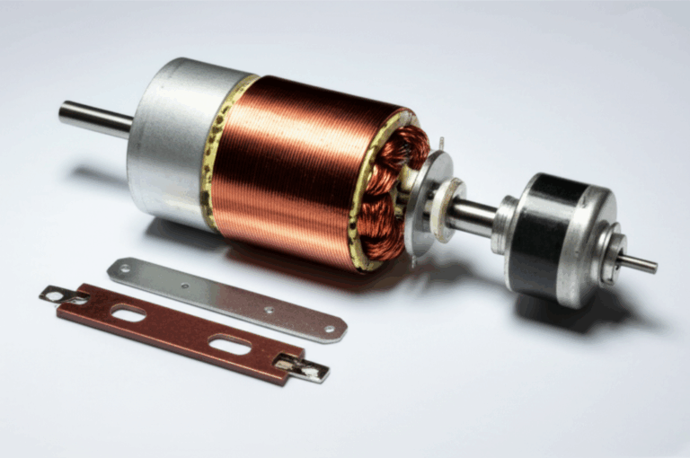
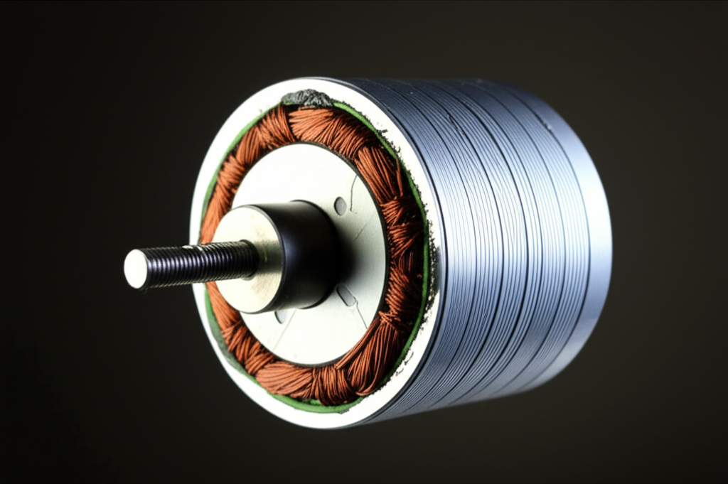
At the heart of the stator sits the core. It looks like a stack of thin steel rings with tooth-like projections. Those teeth form slots. We push copper windings into those slots.
Why thin laminations instead of one solid ring? Because AC magnetic fields stir up swirling currents in solid metal called eddy currents. Those currents waste energy as heat. Thin, electrically insulated sheets choke that swirling motion which cuts eddy current losses. That is why high quality stator core lamination matters so much.
I choose electrical steel grades for the core because their silicon content lowers hysteresis losses and improves magnetic properties. You may hear “electrical steel laminations” or “silicon steel.” Both point to steels tuned for low core losses under alternating magnetic flux. If you want a primer on materials this page on electrical steel laminations gives a good overview of why the steel is stacked and insulated.
Those slots I mentioned house the coils. Their shape and spacing influence the magnetic circuit and the winding pattern. Narrow slots can reduce leakage flux. Wider slots can fit thicker wire which lowers winding resistance. I watch slot geometry like a hawk because it changes efficiency and thermal behavior.
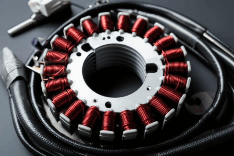
Stator windings: copper coils and insulation
The copper windings carry current which creates the stator’s magnetic field. More turns give more magnetomotive force for a given current. Thicker wire lowers resistance which reduces copper losses that show up as I²R heat.
Insulation is not optional. It keeps turns from shorting together or to ground. I pay attention to insulation class because temperature kills motors. Class B, F, H refer to materials rated for different maximum temperature rises that often fall between about 130°C and 200°C. If I expect hot spots I go with higher class insulation or better cooling.
I also watch the slot fill factor. That’s the fraction of the slot area filled with copper. Higher slot fill usually reduces resistance and boosts efficiency. I’ve seen random-wound machines with 30 to 60 percent fill. I’ve also seen formed-coil stators push 60 to 80 percent. Tighter packing needs care. You need proper insulation and impregnation to avoid partial discharge and abrasion.
Stator frame: structure and cooling
The frame holds everything together. It carries the core. It provides mounting points. It sheds heat. I choose frames with fins or housing features that promote airflow or coolant flow. In large machines the frame often channels water or oil around the core. Small machines rely on conduction to the frame plus airflow from a shaft fan or external blower.
The fundamental principle: How a stator creates magnetism
I’ll never forget the first time I wrapped a nail with wire and hooked it to a battery. The nail jumped to a screw like it suddenly cared. That simple trick explains the stator.
Electricity and magnetism in plain English
When current flows through a conductor it creates a magnetic field. Hans Christian Oersted noticed that in the 1800s when a compass needle deflected near a live wire. A coil multiplies that effect because each loop adds its own little field in the same direction. Put that coil around an iron core and the iron guides and strengthens the field because it has high permeability.
The right-hand rule and field strength
If I curl my right-hand fingers in the direction of current through the coil my thumb points to the coil’s magnetic north pole. Reverse the current and the pole flips. Field strength depends on the number of turns and the current. Double either and the magnetization roughly doubles until the iron starts to saturate.
I watch saturation because once the iron reaches its limit the field stops growing in step with current. You waste power as heat. Flux density in the core tells me how close I am to that limit.
Stators in action: Motors vs. generators
Here’s where the stator earns its keep. Same coils. Same core. Different dance.
In electric motors: rotating magnetic field and torque production
In AC motors the stator builds a rotating magnetic field. We call it an RMF. Feed three-phase stator windings with three currents separated by 120 electrical degrees and the combined field rotates smoothly around the stator bore. That rotation pulls the rotor along. The air gap is small which keeps magnetic reluctance low so the field crosses efficiently.
- Induction motor stator: In an induction motor the rotor has bars or a squirrel-cage arrangement. The stator’s RMF sweeps past the rotor. This relative motion induces currents in the rotor by Faraday’s Law. Those rotor currents build their own magnetic field that opposes the slip by Lenz’s Law. The two fields interact and produce torque. The rotor never quite catches the RMF under load which is why we call it asynchronous.
- Synchronous motor stator: In a synchronous motor the rotor carries permanent magnets or a wound field. The rotor locks step with the RMF. Torque happens through direct alignment of stator and rotor poles. Control of excitation handles power factor and torque in these machines.
- Brushless DC (BLDC) motor stator: In BLDC motors the stator typically carries the windings and the rotor carries permanent magnets. Electronic commutation feeds the stator phases in a timed sequence that mimics DC motor behavior. The stator still creates a rotating field. The controller decides when and how.
- Servo and stepper motor stators: In servo motors the stator design favors precise torque control and low inertia. In stepper motors the stator has many poles and a special winding pattern. The controller energizes phases in steps which moves the rotor in discrete angles.
I remember rebuilding a small three-phase induction motor and noticing scorched windings on two slots that sat opposite each other. The rotor looked fine. The issue traced to poor airflow around those slots. Once I improved cooling the motor stopped hot spotting. Torque rose back to spec since the copper could carry rated current without thermal derating.
A key motor takeaway: the stator creates a rotating magnetic field that pulls or pushes the rotor. Everything else builds on that.
In generators and alternators: induction and voltage generation
Flip the script and the stator becomes the catcher’s mitt. The rotor carries magnets or a wound field that spins inside the stator. The changing magnetic flux through the stationary coils induces voltage by Faraday’s Law. Lenz’s Law ensures the induced current resists the change that created it which is why you feel mechanical load when you hook the generator to an electrical load.
- Alternator: In a typical automotive alternator the rotor is a rotating electromagnet fed through slip rings. The stator carries stationary three-phase windings. As the rotor spins the flux in the stator changes which induces three-phase AC that later gets rectified to DC for the battery and electrical system.
- Wind turbine generator: Many wind turbines use permanent magnet synchronous generators with stator windings that output variable-frequency AC that converts to grid frequency. The stator sees wide speed and load swings which makes cooling and insulation aging important.
- Hydroelectric generator: Huge hydro generators use wound-field rotors with stationary stator windings. The physics stays the same. The scale changes which makes lamination quality and cooling vital.
The generator takeaway: the stator holds coils that “catch” time-varying magnetic flux from the rotor so voltage appears across the terminals.
Types of stator windings and why they matter
You can wire a stator a dozen ways. Each choice changes performance and cost.
Single-phase vs. three-phase stators
Single-phase stators show up in small appliances and simple systems. They need start windings or capacitors to create a phase shift that gets the rotor moving. Three-phase stators deliver smoother torque and higher power density. They produce a naturally rotating magnetic field without extra tricks. Industrial motors lean on three-phase designs for efficiency and reliability.
Concentrated vs. distributed windings
- Concentrated windings bundle each phase into groups that sit over one or two teeth. They reduce copper length and boost slot fill which can raise efficiency and power density. They often increase harmonic content in the air-gap flux which can raise losses or acoustic noise. BLDC and traction motors often use concentrated windings for compactness.
- Distributed windings spread each phase across many slots. They smooth the air-gap flux which reduces harmonic torque ripple and acoustic noise. They use more copper length which can raise resistance and copper losses. Many industrial induction motors use distributed windings for lower harmonics and better power factor.
I choose concentrated windings for high power density and when the inverter can handle the harmonics. I choose distributed windings for quiet operation and smoother torque.
Design choices that make or break a stator
Here’s where good machines separate from average ones. The stator is a magnetic circuit with thermal and electrical constraints. Balance those and you win.
Magnetic circuit basics: air gap, flux, reluctance, permeability
The stator and rotor form a magnetic circuit linked by the air gap. The air gap has high magnetic reluctance compared to iron. Keep it small and uniform to strengthen the coupling. The core material has high permeability which lowers reluctance and eases flux flow. I watch mechanical tolerances because uneven air gaps cause unbalanced magnetic pull and noise.
Flux density tells me how hard I’m pushing the iron. More flux can mean more torque or voltage. Too much flux drives the core into magnetic saturation which wastes power and creates heat.
Losses: copper, hysteresis, eddy currents, and core losses
Losses show up in two main buckets.
- Copper losses: These are I²R losses in the windings. Higher current or higher resistance means more heat. Bigger wire reduces resistance. Better slot fill helps. Shorter end turns cut wasted copper.
- Core losses: These happen in the stator steel due to alternating flux. Hysteresis losses come from flipping magnetic domains each cycle. Eddy current losses come from induced currents in the steel sheets. Thin insulated laminations stand between you and a hot stator. Good steel grades cut core losses further. I’ve seen data where core losses make up 10 to 30 percent of total motor losses. That depends on frequency, material, and flux density.
If you want to go deeper into material stacks and options for high performance cores you can browse motor core laminations. It connects material choice to performance which tracks with what I measure on the bench.
Thermal management and cooling strategies
Heat kills insulation. Insulation failure kills stators. I plan for:
- Conduction to the frame with thermal interfaces that reduce contact resistance
- Convection with internal fans or external blowers for small machines
- Liquid cooling jackets for high power density stators like EV motors
- Vacuum pressure impregnation to stabilize windings and improve heat transfer
I design to keep winding temperatures within the insulation class. I also check hot spots near end turns and around slots that sit opposite each other because local velocity can drop there.
Power factor, reactive power, and efficiency
In AC machines the stator draws reactive power to establish the magnetic field. That reactive component does not produce mechanical work yet it affects current draw and copper losses. Synchronous machines can control field excitation which lets me correct power factor. Induction motors often run at lagging power factor under light load. As load rises the power factor improves.
Efficiency rises when I reduce both copper and core losses. I’ve seen optimized stator designs pick up 0.5 to 2 percentage points of efficiency in industrial motors. Specialized designs can gain more with advanced materials and cooling.
Flux density, saturation, and flux linkage
Flux density in the core should stay below the knee of the B-H curve for the chosen material. Push past it and the core saturates which raises magnetizing current and core losses. Flux linkage tells me how effectively the stator field couples to the rotor. Better coupling means more torque per amp in motors and more volts per rpm in generators.
I’ve learned to respect the air gap here. A few tenths of a millimeter can swing performance in compact machines. Tight tolerances pay off in torque density and quiet operation.
Common stator issues and how I troubleshoot them
When a motor acts up I usually start with simple checks.
- Overheating: If the frame runs hot I check airflow, load, and voltage balance. High core losses point to wrong supply frequency or material issues. High copper losses point to overload or low voltage that drives current up.
- Winding short circuits: Inter-turn shorts show up as reduced inductance and hotter spots. A surge test can catch them. I also use an IR thermometer to scan the stator after a short run.
- Insulation failure: I use a megohmmeter to test insulation resistance to ground. Low readings suggest contamination or aging. Partial discharge testing can reveal insulation stress in high voltage stators.
- Unbalanced magnetic pull: Noise or vibration can point to uneven air gap. I check bearings and rotor runout. I also look for stator core shift in the frame.
Prevention beats repair. Good impregnation, proper wire dressing, and clean slot liners avoid many headaches. Keeping the machine within its thermal limits keeps insulation healthy.
Real-world applications and what I’ve learned
I’ve worked with a range of machines. The stator rules stay the same. The trade-offs shift.
- Induction motors: Workhorses in industry. The stator uses distributed three-phase windings and a laminated iron core. Efficiency hinges on copper fill, good electrical steel laminations, and airflow. Torque depends on slip and rotor design. The stator sets the stage.
- Synchronous motors: High efficiency and controllable power factor. The stator looks similar to an induction motor though design adjusts for harmonics and voltage stress. Field control can correct power factor at the plant level which saves on utility penalties.
- BLDC and permanent magnet motors: The stator carries concentrated windings in many traction motors. The rotor carries strong magnets. Electronic commutation drives the stator phases to produce precise torque. Stator thermal design becomes the bottleneck because magnets hate heat. I choose tight slots and solid impregnation to pull heat into the frame. If you want to see core construction specific to these machines you can look at a bldc stator core.
- Stepper motors: The stator has many poles and small teeth. Winding patterns create discrete steps. Flux harmonic content matters because it sets torque ripple and smoothness.
- Servo motors: Similar to PM motors though optimized for low inertia and high bandwidth control. I pick stator designs that reduce cogging torque and iron losses at high electrical frequency.
Generators tell similar stories.
- Wind turbine generators: Variable speed drives the choice of materials. The stator must handle wide frequency ranges which change core losses. Cooling and insulation class drive reliability.
- Hydroelectric generators: Massive machines that run slow with high torque. Stators use thick cross-sections and robust frames. Lamination quality and slot insulation define long-term health.
- Automotive alternators: Compact and hot. The stator lives near the engine. I focus on thermal path and insulation life. The rotor’s field current adjusts output which means the stator sees varying load cycles.
One more note. When I teach apprentices about torque production I grab a simple ring magnet and a nail. I show how the magnet “wants” to align with the nail’s field. The stator’s rotating magnetic field is that ring magnet on a conveyor belt. The rotor chases it. That image sticks which helps them see why phase sequence reversals flip rotation and why unbalanced phases cause rough running.
Quick data points that shape decisions
A few numbers keep me honest. They line up with what I see in manufacturer specs and design texts.
- Optimized stator design can add roughly 0.5 to 2 percentage points of motor efficiency in industrial settings
- Core losses in the stator often account for 10 to 30 percent of total losses depending on frequency, material, and flux density
- Copper losses can take 20 to 50 percent of total losses which makes slot fill and wire gauge critical
- Insulation classes commonly rate windings to withstand temperature rises that place hot spots between about 130°C and 200°C depending on class
- Stator winding failures account for a large slice of motor failures often reported in the 30 to 50 percent range
- Advanced core materials like amorphous metals can cut core losses sharply compared to conventional silicon steel though they complicate fabrication
- Slot fill often lands around 30 to 65 percent for random windings and 60 to 80 percent for formed coils
- EV traction motors push power density to 5 to 10 kW per kg with aggressive stator design and cooling while general industrial motors often sit around 1 to 2 kW per kg
I keep these numbers in mind during trade-offs. They frame where time and money pay off.
Conclusion: The unseen heartbeat of electric machines
The stator stays still yet it drives everything. Feed its windings and it builds a magnetic field that rotates or stands as needed. In a motor that field pulls on the rotor and makes torque. In a generator it catches changing flux from the rotor and produces voltage.
I focus on three things when I design or diagnose a stator.
- Materials: Good laminations and proper insulation save watts and extend life. If you want to see how rotor design complements this you can browse rotor core lamination. The two halves must match.
- Geometry: Slot shape, tooth width, and air gap set magnetic and thermal behavior. Little changes can swing performance.
- Heat: Manage copper and core losses with a clean thermal path. Respect insulation class limits.
Get those right and the machine hums. Miss them and you get heat, noise, and failure. The stator may not move. It still acts like the heartbeat of every motor and generator I touch.