How Does a Stator Charge a Battery? Understanding the Core Mechanism
Table of contents
- Introduction: Why the stator matters and how I learned the hard way
- The fundamental principle: Electromagnetic induction
- What is electromagnetic induction?
- Stator vs. rotor: Who does what?
- The journey of electricity: From stator to battery (step-by-step)
- Step 1: Generating AC power
- Step 2: Rectifying AC to DC
- Step 3: Regulating voltage
- Step 4: Delivering power to the battery and system
- Key components of a stator charging system
- Specs and typical values you can trust
- Common problems and how I troubleshoot them
- Symptoms of a failing stator or regulator/rectifier
- How to test your stator with a multimeter
- How to test your regulator/rectifier
- Voltage drop and wiring issues
- Stator vs. alternator: What’s the difference and why it matters
- What affects stator output and lifespan
- Maintenance tips for a healthy charging system
- Final thoughts: Keep your ride powered and your battery happy
Introduction: Why the stator matters and how I learned the hard way
I still remember the ride that taught me to respect stators. My motorcycle started fine that morning. Ten miles later the dash dimmed then the headlight flickered then the engine coughed. I limped to the shoulder with a dead battery and a long walk ahead. The culprit wasn’t the battery. It was the charging system. That day I learned exactly how a stator charges a battery and why a tiny box called a regulator/rectifier can make or break your trip.
If you ride a motorcycle or an ATV or a snowmobile or run a small engine on a boat you rely on a stator charging system. Cars use belt-driven alternators most of the time. Bikes and small engines often use a permanent magnet stator paired with a flywheel. Different hardware same job. Convert engine motion into electrical energy that recharges the battery and powers everything else.
In this guide I’ll explain the whole process in plain English. I’ll show you how the stator and rotor work together. I’ll walk you through the rectifier and the voltage regulator. I’ll share the tests I use when a battery won’t charge. I’ll cover common symptoms. I’ll also explain alternator vs stator charging so you can see why your vehicle uses one or the other. By the end you’ll know how to diagnose issues like undercharging or overcharging. You’ll know what “stator output AC voltage” should look like at idle versus at higher RPM. You’ll know when a regulator/rectifier fails and cooks a battery. Most of all you’ll understand the system from end to end.
The fundamental principle: Electromagnetic induction
What is electromagnetic induction?
The heart of this system beats with electromagnetic induction. Faraday’s Law says a changing magnetic field through a coil creates voltage. Lenz’s Law says the induced current pushes back against the change. That’s the physics in a nutshell. If you spin magnets past a coil of wire the coil sees a changing magnetic field. That change produces alternating current. That’s AC. It alternates positive then negative as the magnets sweep by.
In practical terms the engine spins the flywheel. The flywheel carries permanent magnets. Those magnets pass over copper windings in the stator. The changing magnetic flux induces voltage in the windings. No battery is required to create that raw AC. The system generates power as long as the engine turns.
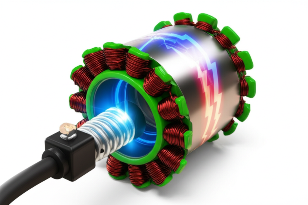
Stator vs. rotor: Who does what?
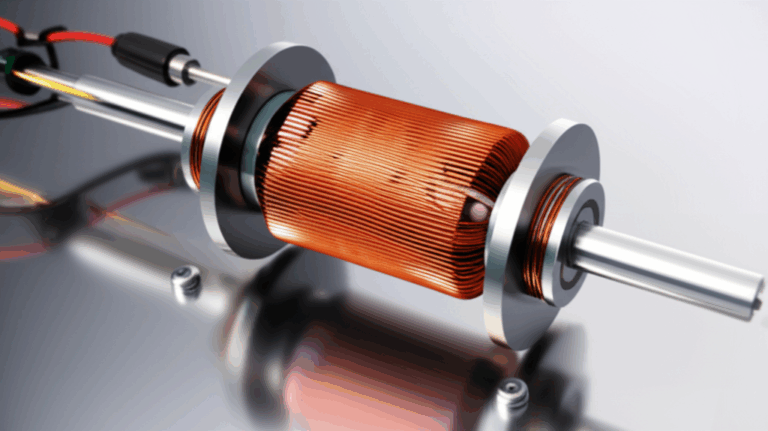
Names matter. The stator stays still. It’s a ring of laminated steel packed with copper windings mounted to the engine case. The rotor rotates. In many bikes the rotor is the flywheel with magnets embedded around its inner circumference. Spin the rotor and you sweep magnetic fields across the stator coils. The coils output AC. Simple concept. Beautiful execution.
Some vehicles use a single-phase stator. Many use a three-phase stator because it delivers smoother power and higher efficiency. Three-phase stators have three sets of windings spaced 120 electrical degrees apart. Each phase produces a sine wave out of step with the others. Combine them through a rectifier and you get more stable DC with less ripple.
The journey of electricity: From stator to battery (step-by-step)
Step 1: Generating AC power
The stator’s job starts with the magnets on the flywheel. As engine RPM climbs the magnets pass faster. That raises AC output voltage and available current. On a typical motorcycle I often see 20 to 30 VAC per phase at idle then 60 to 70 VAC per phase at 5000 RPM with the stator unplugged from the regulator/rectifier. Output depends on design and pole count and coil turns. Output is also largely linear with RPM up to a point.
In a multi-phase setup you measure between phase leads. For a three-phase stator you measure between A-B then B-C then C-A. Healthy systems show similar voltages across all pairs. A big mismatch points to a damaged winding.
Step 2: Rectifying AC to DC
Batteries need DC. Stators make AC. That’s why you need a rectifier. The rectifier uses diodes to pass current in one direction only. It flips the negative half of the AC waveform to positive then smooths the result. Many bikes combine the rectifier with a voltage regulator in a single regulator/rectifier unit. You’ll see this called an R/R in service manuals. That unit takes the three-phase AC from the stator and outputs pulsating DC that the battery can accept.
Here’s the quick version of the rectifier conversion process. Each diode pair guides current from the highest positive phase to the battery then shunts the negative portion to ground. With three phases the pulses overlap which reduces ripple. That keeps lights steadier and electronics happier.
Step 3: Regulating voltage
Left unchecked the stator would deliver voltage that swings high as RPM climbs. Your battery wouldn’t like that. Your ECU and lights wouldn’t either. The voltage regulator holds output in a safe range. For a 12V system I look for about 13.8 to 14.8 V at the battery at cruising RPM. Some systems sit closer to 14.2 V. Idle can be a bit lower. The key is stability once you raise RPM.
Many motorcycle R/R units are shunt regulators. They dump excess current to ground as heat. That’s why these units get hot. Modern MOSFET shunt regulators run cooler than old-school silicon types. Some systems use series regulation which limits current earlier and runs cooler under light loads. Either way the goal is the same. Keep voltage from spiking and prevent battery overcharging.
Step 4: Delivering power to the battery and system
The regulated DC flows into the battery and the vehicle’s electrical system at the same time. If your headlights are on the R/R feeds them. If the engine control unit needs power it gets it. The battery acts as a buffer and storage device. While riding the stator covers most of the load. When demand spikes at idle the battery fills the gap. When demand drops at higher RPM the battery charges.
Key components of a stator charging system
Over the years I’ve opened plenty of charging systems. The same cast of characters keeps showing up.
- Stator assembly: The stator frame holds copper windings around a ring of laminations. Those laminations are thin sheets of electrical steel. They cut down on eddy currents and core losses which keeps heat down. If you want to understand why the steel stack matters read up on stator core lamination. Good laminations help efficiency and longevity.
- Flywheel with permanent magnets: This is the rotor in many small engines. Magnets line the inner surface and sweep over the stator poles. Some rotors use additional rotor core lamination structures to focus magnetic flux and reduce losses.
- Regulator/rectifier unit: The R/R converts three-phase AC to DC then regulates voltage. It often sits in an airflow path and bolts to a heat sink. It runs hot by design. That means placement and cooling matter.
- Battery: Lead-acid batteries are common on motorcycles and ATVs. Lithium-ion batteries appear more often now. Both need controlled charging. Lead-acid likes that 13.8 to 14.8 V range at the terminals. Lithium systems often require a compatible regulator and sometimes a battery management system.
- Wiring harness: Connectors tie the system together. Stator to R/R. R/R to battery positive and ground. Good grounds are essential. Bad connectors create resistance which leads to heat then failures.
- Optional extras: Some systems add a fuse or a circuit breaker between the R/R output and the battery. Some include a dedicated sense wire for accurate regulation. Always check your wiring diagram before testing.
I also pay attention to material quality. The laminations and the way the steel is stacked change performance. If you want the bigger picture beyond stators look at electrical steel laminations. Laminations exist in stators and rotors across motors and generators because the physics is the same.
Specs and typical values you can trust
Numbers keep us honest. Here are the targets I use when diagnosing a 12V system.
- Stator AC output no load: Roughly 20 to 70 VAC per phase per 1000 RPM depending on the design. I often see around 20 to 30 VAC at idle then 60 to 70 VAC at 5000 RPM on common bikes when the stator is disconnected from the R/R. Read between all phase pairs and compare. One low phase usually means one bad coil.
- Stator coil resistance: Typically 0.1 to 1.0 ohm per phase. The exact spec lives in the service manual. Infinite resistance means an open winding. Very low resistance to the engine case means a short to ground.
- Battery voltage engine off: 12.6 to 12.8 V for a healthy fully charged lead-acid battery. 12.4 V suggests partial discharge. 12.0 V means it’s very low.
- Battery voltage engine running at idle: 13.0 to 13.8 V is common. Some systems sit lower at idle. Voltage should rise with RPM.
- Battery voltage at 3000 to 5000 RPM: Aim for 13.8 to 14.8 V. Consistently lower indicates undercharging. Consistently higher means overcharging which points to a bad regulator.
- Power output: Many motorcycle stators deliver 150 to 500 W of DC output. Small bikes sit lower. Big touring bikes sit higher. Accessories eat into that budget quickly.
- Temperature: R/R units can run hot. Prolonged operation near their thermal limits shortens life. Good airflow helps.
- Failure patterns: Heat leads the list for both stators and R/R units. Heat breaks down insulation on windings and it cooks semiconductors in regulators.
Common problems and how I troubleshoot them
Symptoms of a failing stator or regulator/rectifier
I look for patterns. Here are the red flags that send me to the charging system.
- Battery not charging while riding or dying overnight after a ride
- Dim or flickering lights that worsen as RPM drops
- Engine misfires or stumbling at low voltage
- Blown fuses or a burning smell near the R/R
- An R/R heat sink that runs unusually hot at modest loads
- Dashboard voltage that drops under 13.5 V at cruise or spikes above 15 V
If you ride a motorcycle the classic “bad stator symptoms” include a dead battery after a long highway run. That points to undercharging at speed or a failing R/R. If lights get brighter when you rev then go dim at idle you might still be ok because some stator systems produce less at idle. If lights stay dim at high RPM you’ve likely got a problem.
How to test your stator with a multimeter
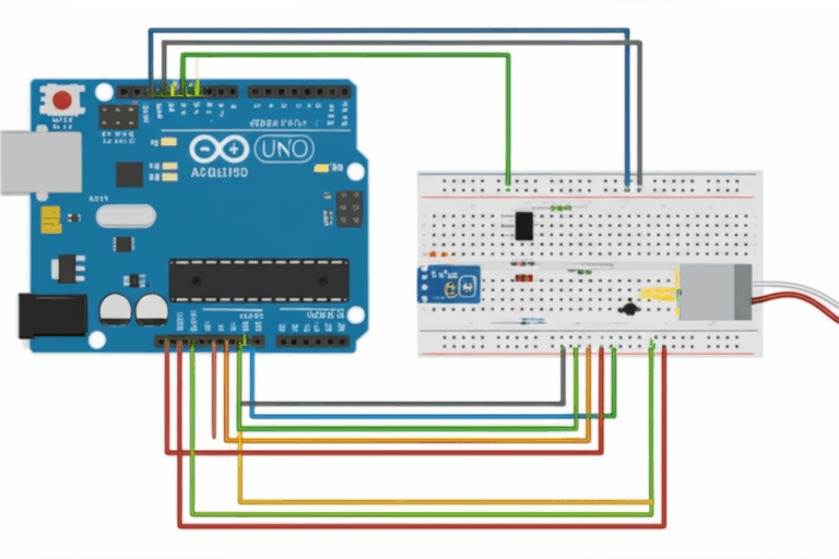
I carry a cheap digital multimeter. It’s worth its weight in gold when you suspect an ATV stator charging problem or a boat stator charging issue. Here’s my basic flow. The engine and vehicle should be safe to run. The service manual is your friend. Follow it where values differ.
1) Visual inspection
- Check the stator connector for burnt pins or melted housings.
- Look for chafed wires around the flywheel cover and along the harness.
- Check for oil intrusion where it shouldn’t be. Some stators live in engine oil by design. Others should stay dry.
2) Resistance and continuity tests (engine off)
- Unplug the stator from the R/R.
- Measure resistance between phase leads. On a three-phase stator check A-B then B-C then C-A. Values should match and fall in the spec often 0.1 to 1.0 ohm.
- Measure resistance from each phase lead to engine ground. You want open circuit or very high resistance. Any reading near zero means a short to ground.
3) Open circuit stator test (AC voltage test)
- With the stator still unplugged start the engine.
- Set the meter to AC volts. Measure between each pair of phase leads.
- Note voltage at idle then at 3000 to 5000 RPM.
- Healthy stators show rising voltage with RPM and similar readings across all pairs. A weak or dead phase indicates coil damage.
4) Short circuit test cue
- If your meter shows very low resistance between a phase and ground the stator has a ground fault. That explains blown fuses and weak output.
5) Stator phase balance
- Compare A-B vs B-C vs C-A. A big difference flags a bad coil or a damaged connection.
A question I get a lot sounds like this. How many volts should a stator put out. The answer depends on engine and design. I look for rough ranges then verify with the manual. If your readings sit way below the range at all RPM you likely have a bad stator.
How to test your regulator/rectifier
Once the stator checks out I turn to the R/R. This answers “how to diagnose a bad regulator/rectifier” without guesswork.
1) DC battery test at idle and RPM
- Reconnect the stator to the R/R.
- Measure DC voltage at the battery terminals with the engine running.
- At idle you might see 13.0 to 13.8 V. At 3000 to 5000 RPM you should see 13.8 to 14.8 V.
- If voltage never climbs above 13.5 V you’ve got undercharging. If it climbs above 14.8 to 15 V you’ve got overcharging.
2) Heat check
- Warm the bike. Feel the R/R heat sink carefully. It will be hot so be cautious.
- Excessive heat at low load can point to internal failure.
3) Diode test
- Some service manuals include a diode test across R/R terminals with a meter’s diode mode. Follow the manual since pinouts vary.
If the R/R fails to regulate you’ll see battery overcharging from the stator at highway speed. That boils electrolyte in lead-acid batteries and damages lithium packs. If the R/R fails to pass current you get undercharging and a dead battery after a ride.
Voltage drop and wiring issues
I never overlook wiring. I’ve chased more than one charging system “failure” that turned out to be a corroded connector. Here’s my quick wiring checklist.
- Measure DC voltage at the R/R output lead then at the battery positive. The difference is voltage drop through the harness. Anything above a few tenths matters under load.
- Clean grounds. A loose or corroded ground creates wild symptoms. I clean the frame ground point until it shines.
- Inspect the stator to battery wiring for overheated insulation. Resistance creates heat. Heat creates more resistance. That spiral ends poorly.
- Follow the regulator rectifier wiring diagram in your service manual. Color codes vary by brand.
- Replace crispy connectors. Don’t ignore a melted stator plug. It will fail again if you don’t fix the root cause.
Stator vs. alternator: What’s the difference and why it matters
I get asked about alternator vs stator charging all the time. Here’s the short version.
- Stator charging systems in motorcycles and small engines usually rely on a permanent magnet rotor and a fixed stator. Magnets supply the field. Output rises with RPM. The regulator bleeds off extra power as heat.
- Automotive alternators use an electromagnet rotor with a field coil. They control output by changing rotor field current. That means they can produce the right amount of power with less waste. They also mount externally and run off a belt. The battery and the alternator work in a tight loop.
Alternator vs magneto charging brings another term into the mix. A magneto is just a generator with permanent magnets that can create enough power for ignition without a battery. Many motorcycle systems look like magnetos with extra windings for charging. The line between terms gets blurry in conversation. What matters is this. Cars use field-controlled alternators. Bikes and small engines usually use permanent magnet stators because they are compact and reliable.
What affects stator output and lifespan
Design choices and real-world use both matter.
- RPM profile: Stator output rises with RPM. Some systems barely charge at idle. That’s normal. Loads like fans and high-wattage headlights can drain the battery at long stoplights if idle charging is weak.
- Heat: Heat kills stators and R/R units. A shunt regulator dumps excess current as heat. Poor airflow cooks it. Heat breaks down enamel insulation on stator windings and invites inter-winding shorts.
- Materials: Good lamination steel and tight stacking reduce core losses. That keeps heat down and efficiency up. If you want to understand why this matters across motors and generators look at motor core laminations.
- Winding insulation: Oil contamination and age degrade the varnish on windings. I’ve pulled covers and found windings darkened and brittle. That stator won’t last.
- Electrical load: High accessory loads can exceed stator capacity. When demand exceeds supply the battery discharges while riding. You’ll see undercharging issues then repeated dead batteries. Size your loads wisely.
- Connector health: Corrosion raises resistance. Resistance drops voltage and raises heat at connectors. That heat melts plugs then takes out R/R units.
- Manufacturing quality: Not all stators are equal. Cheap rewinds might not match resistance or thermal performance. I weigh repair vs replacement carefully. Rewinding can save money. Replacement often saves time.
A word about phases and configuration. Many stators are three-phase because three phases deliver smoother DC after rectification. Some windings use wye (star) connections. Others use delta. That changes voltage and current characteristics. You’ll see those details in the service manual rather than on the side of the bike. If you need the concept think of star as higher voltage per phase and delta as higher current per phase at the same RPM.
Maintenance tips for a healthy charging system
A little care goes a long way.
- Keep connectors clean and tight. I use dielectric grease to protect contacts but I never slather it on the actual pin surfaces.
- Inspect harnesses for chafing. Moving parts love to find wires and rub them raw.
- Ensure the regulator/rectifier has airflow. Don’t tuck it behind a hot radiator without a plan.
- Check battery health. A tired lead-acid battery draws high current which runs the R/R hard. A healthy battery stabilizes voltage.
- Test periodically. A quick DC check at the battery while idling and at 3000 RPM tells you a lot.
- Follow torque specs when installing a new stator. Loose bolts let the stator move which can clip the rotor. That ends badly.
- Use proper parts. Stator winding diagram and color code vary by brand. Stick with the correct regulator rectifier wiring. Don’t mix random connectors just because they fit.
Real-world examples you can learn from
I’ll share three quick stories that shaped how I troubleshoot.
- The overcharging cruiser: The battery smelled like rotten eggs after a long ride. The dash showed 15.5 V at cruise. The stator AC looked great. The R/R had failed high. I replaced it and added better airflow. Battery recovered after a safe charge.
- The undercharging ATV: Lights were dim and the winch killed the battery. Stator AC at idle was low. At 4000 RPM the AC hit the expected range. The R/R output at the battery stayed under 13.5 V. I found a cooked connector on the R/R ground. I cleaned and crimped a new terminal. Charging recovered immediately.
- The phantom stator failure on a small outboard: Owner replaced the stator after seeing low DC at the battery. The new stator didn’t fix it. I measured AC no-load and it looked fine. I then found a hidden inline fuse holder with a corroded spring. Voltage drop across that tiny piece was massive. New fuse holder solved the “stator” problem.
Answers to questions I hear often
- Why is my stator not charging? Start with the basics. Check connectors. Test stator resistance and AC output. Then test the R/R output at the battery. Many “bad stators” turn out to be wiring or regulator faults.
- How do stators generate AC current? Spinning magnets change magnetic flux through copper coils. That change induces AC voltage. The coil doesn’t care which direction the magnet moves. It only cares that the flux changes.
- Do stators always use AC and why? Yes for these systems. Permanent magnet setups produce AC directly. Batteries need DC so we rectify it.
- How much power does a stator generate? It depends. Many bikes sit between 150 and 500 W. Bigger touring machines run higher because they power heated grips and big lights and electronics.
- How do I measure stator voltage output correctly? Unplug the stator from the R/R. Set your meter to AC. Measure between phase pairs. Raise RPM. Compare phases. Then reconnect and measure DC at the battery with the engine running.
- Can a stator overcharge a battery? Not on its own. Overcharging comes from a failed regulator. Replace it quickly to avoid battery damage.
- What about snowmobiles and golf carts? The same principles apply. Snowmobile stator charging systems look like motorcycle systems. Gas golf carts often use similar magneto-style charging coils with a rectifier. Outboard motor stator charging follows the same AC to DC conversion and regulation model.
From materials to performance
I mentioned laminations earlier because they matter. The stator core is a stack of thin insulated steel sheets. That stack reduces eddy currents and cuts core losses. It also shapes the magnetic path which boosts efficiency. The rotor core can use laminations as well. You see this in many motors and generators because the physics doesn’t change from one machine to the next. If you’re curious about the material science behind these stacks you can dive into electrical steel laminations. Better steel and tighter stacking translate into less heat and more reliable output.
If you ever tear down a worn stator you might find darkened windings and cracked varnish. Heat and vibration do that. Some riders consider a rewind. I weigh rewind vs replacement on three points. The cost and the quality and the turnaround time. A quality rewind that matches spec can perform well. A poor rewind raises resistance or lowers output and that wastes money.
Putting it all together: A simple mental diagram
When I explain this to friends I draw the same simple diagram in the air.
- Rotor with magnets spins on the crankshaft.
- Stator with coils sits fixed around it.
- Coils generate three-phase AC.
- Rectifier converts AC to DC.
- Regulator holds DC voltage around 14 V.
- Battery and loads consume DC as needed.
That’s it. If you follow the path you can troubleshoot any point in the chain. If the stator AC is strong and balanced yet the battery charges weakly the R/R or wiring is at fault. If the stator AC is weak on one phase the stator is at fault. If everything tests fine yet the battery still dies you either have an excessive load or a bad battery.
Pro tips that save time and parts
- Test before you replace. Guessing gets expensive.
- Measure AC with the stator disconnected from the R/R. Otherwise the regulator can mask stator output.
- Measure DC at the battery with the system fully connected and warmed up.
- Use the service manual for specs. Stator resistance values vary by model.
- Do not ignore grounds. A bad ground mimics a bad regulator every time.
- Consider the ride profile. Short trips with big loads can leave even a healthy system behind.
Closing the loop on alternator vs stator charging
One more comparison because people ask. Alternators in cars regulate by changing field current which keeps heat down at the regulator. Stator systems regulate by shunting excess current which dumps heat into the regulator and the stator. That difference explains why motorcycle R/R units fail often. The hardware choice makes sense though. Permanent magnet stators are compact reliable and cheap to package on small engines.
Final thoughts: Keep your ride powered and your battery happy
I rode home from that dead-battery day with a new respect for charging systems. I also carried a new multimeter. Since then I’ve helped friends with motorcycle charging system troubleshooting and sorted more than one ATV stator charging problem. The process never changes. Understand the path from spinning magnets to stable DC. Test the stator. Test the regulator/rectifier. Check wiring and grounds. Keep heat in check. Choose quality parts with good lamination stacks and solid windings. When you do that your battery stays happy and your lights stay bright.
If you want to dive deeper into how steel stacks shape performance you can skim the bigger picture around stator core lamination, rotor core lamination, and motor core laminations. Those pieces turn the theory of Faraday’s Law into reliable power you can count on every time you thumb the starter.
Ride safe and keep that meter handy.