How Does a Motorcycle Stator Work? Your Guide to Motorcycle Electricity Generation
Table of Contents
- What I Learned The First Time My Bike Stopped Charging
- What Is a Motorcycle Stator and Why It Matters
- The Core Parts: Stator, Flywheel, and Magnets
- The Principle in Plain English: Electromagnetic Induction
- Step by Step: From Engine Rotation to Battery Charging
- Single-Phase vs Three-Phase Stators
- What a Charging System Diagram Looks Like
- How Engine RPM Changes Stator Output
- How the Rectifier and Regulator Protect Your Bike
- Common Symptoms of a Bad Stator
- How I Test a Motorcycle Stator With a Multimeter
- Ground Tests, Open Circuits, and Shorts Explained
- Typical Specs You Can Expect
- Why Stators Fail and How to Prevent It
- Oil-Cooled vs Dry Stators
- When to Replace vs Rewind a Stator
- Choosing OEM vs Aftermarket Parts
- Upgrades That Actually Help
- Quick Troubleshooting Flow You Can Use Today
- Frequently Asked Questions
- Final Thoughts
What I Learned The First Time My Bike Stopped Charging
The first time my motorcycle died at a traffic light I thought the battery had given up. The horn had sounded tired that morning and my headlights looked dim on the garage wall. I jump-started the bike and rode to work anyway. That was a rookie move. The bike stalled again on the way home and wouldn’t crank. I tested the battery. It read low. Then I learned a lesson that stuck with me. The battery on a bike isn’t the main power plant once the engine runs. The charging system is. At the center of that system, the stator quietly does the heavy lifting.
That breakdown pushed me to learn how a motorcycle stator works and how to test it. Since then I’ve helped friends chase no charging issues, replace smoked regulator/rectifier units, and troubleshoot weird electrical gremlins. This guide pulls together what I wish I had known from day one. I’ll explain the parts, the physics in plain English, the tests, and the fixes. I’ll also share real numbers you can expect when you put a multimeter on your bike.
What Is a Motorcycle Stator and Why It Matters
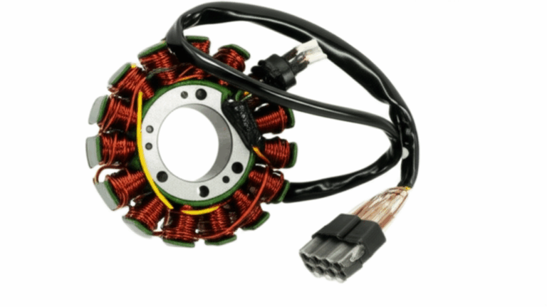
The stator sits at the heart of your bike’s charging system. It’s a set of copper windings mounted to the engine case. It doesn’t spin. The flywheel or rotor spins around it. Together they act like a generator or alternator that turns mechanical energy from the crankshaft into electrical energy.
That electrical energy powers your lights, ignition or CDI, EFI system, dash, and charges your motorcycle battery. Without a working stator and the rest of the charging circuit your battery drains. Then you get dim headlights, weak spark plugs, and a bike that starts once or twice then dies while riding.
People use the words alternator and stator loosely on motorcycles. Many bikes use a permanent magnet alternator. The stator is the stationary part of that alternator. The flywheel with embedded permanent magnets serves as the rotor.
The Core Parts: Stator, Flywheel, and Magnets
Here’s the cast of characters.
- The stator: This is a ring of tightly wound copper coils fixed to the engine case. The windings wrap around a laminated iron core. Those laminations reduce eddy current losses and heat. The core quality matters. If you’re curious about material and construction, the basics of stator core lamination explain why stacked thin sheets work better than solid steel.
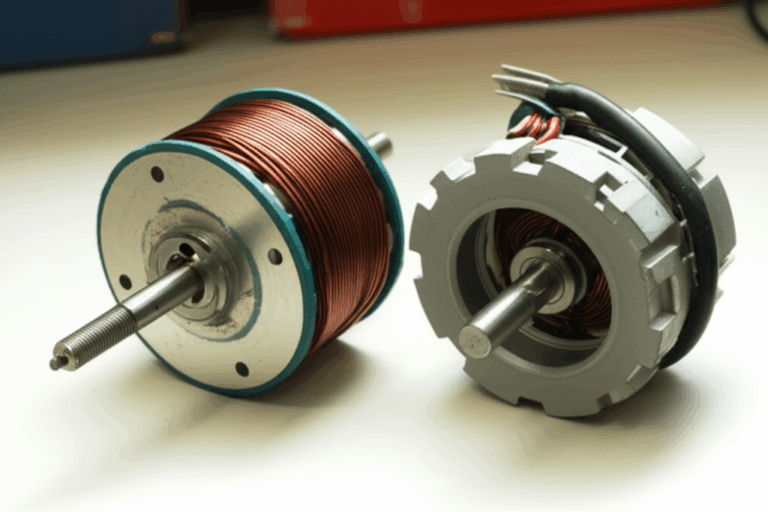
- The flywheel or rotor: This metal drum bolts to the engine crankshaft. It spins around or over the stator. The rotor houses strong permanent magnets that create the moving magnetic field. Manufacturing often uses precise rotor core lamination for efficiency and heat control.
- Permanent magnets: These sit in the flywheel. As they sweep past the stator windings they create changing magnetic flux through the coils. That change drives the whole show.
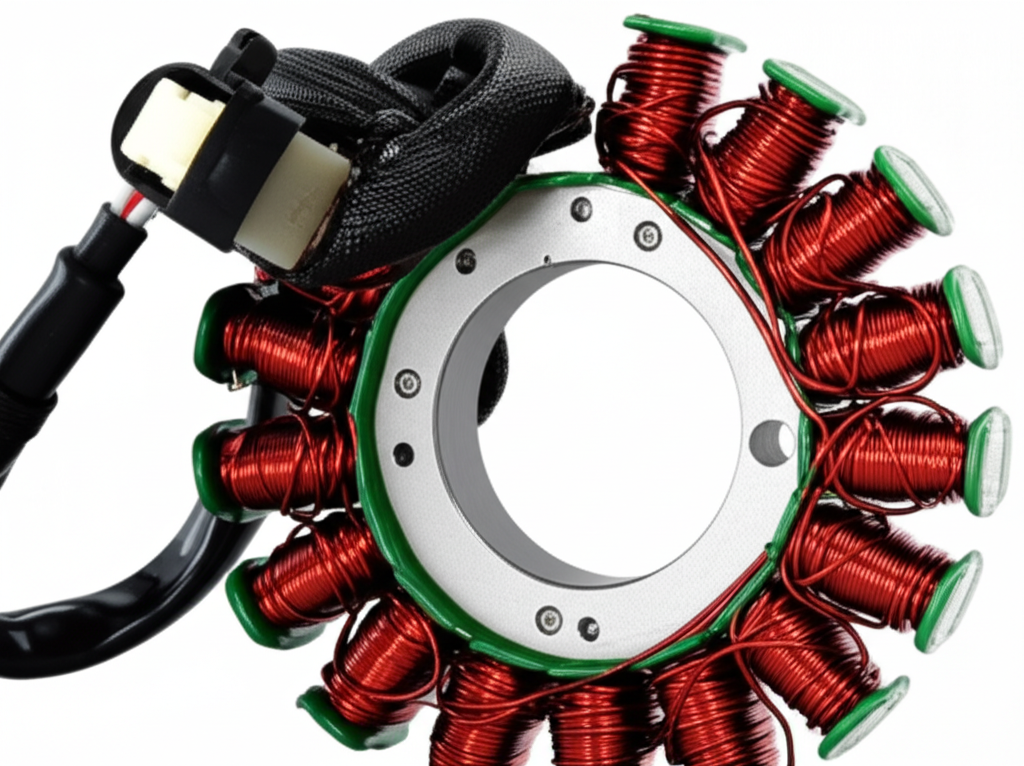
Most modern bikes use three-phase stators with three sets of windings spaced evenly. That design produces smoother power. Older or smaller bikes might use a single-phase stator with fewer coils.
Those coils sit on a laminated core made from electrical steel or silicon steel. Laminations look simple yet they play a big role in performance and heat. If you like the engineering side, you can dig into electrical steel laminations and broader motor core laminations to see how the stack design affects losses and magnetic flux.
The Principle in Plain English: Electromagnetic Induction
Faraday’s Law says a changing magnetic field across a conductor creates voltage. Lenz’s Law adds that the induced current flows in a direction that opposes the change. You don’t need the math to get the picture.
Imagine you wave a magnet past a coil of wire. Every pass makes the magnetic field through that coil rise then fall. That changing flux pushes electrons. So current flows first in one direction then the other. That current alternates. That’s why the stator produces AC voltage.
In a motorcycle, the engine spins the flywheel. The flywheel’s magnets pass by the stator’s copper windings. The flux through those coils changes fast. The faster the engine spins the bigger and faster the change. Voltage rises with RPM. Current capability depends on winding design and magnet strength. The stator generates AC. The bike needs DC to charge the battery and feed electronics. So we convert and regulate it.
Step by Step: From Engine Rotation to Battery Charging
- Step 1: The engine turns the crankshaft. The rotor or flywheel bolts to it so the flywheel spins too.
- Step 2: Permanent magnets in the flywheel sweep past the stator coils. Magnetic flux through the laminated core and copper windings changes constantly.
- Step 3: That changing field induces AC voltage in each coil. Single-phase systems have one pair of coils. Three-phase systems have three sets offset by 120 degrees for smoother output.
- Step 4: The AC output travels to the regulator/rectifier unit. The rectifier section uses diodes to convert AC to DC. That process flips the negative half of the waveform so current flows one way into the battery.
- Step 5: The regulator section holds the DC voltage in a safe charging range. Most bikes target about 13.5 to 14.5 volts at the battery terminals. That protects the battery and electronics from overcharging.
- Step 6: The battery acts like a buffer. It smooths demand spikes from headlights, EFI, and ignition. The charging system supplies power to everything while topping off the battery during cruising and higher RPM.
Three-phase setups use three yellow phase wires from the stator. They feed the rectifier/regulator. You can measure AC voltage between any two phase wires. Single-phase designs usually have two outputs.
Single-Phase vs Three-Phase Stators
Single-phase stators are simple and cheaper. You’ll find them on older bikes, small-displacement motorcycles, and basic scooters. They use fewer coils and produce ripple-heavy output. They can handle basic loads.
Three-phase stators are the norm on modern bikes. They deliver more power, smooth output, and better efficiency. They also handle the higher electrical demands of EFI, powerful headlights, heated grips, and accessories. You can spot them by the three similar-colored wires coming from the engine case, often yellow.
If you’re not sure which you have, check the service manual or the stator wiring diagram for your motorcycle. The harness typically routes phase wires to the regulator/rectifier then onward to the battery and the rest of the charging circuit.
What a Charging System Diagram Looks Like
Most charging system schematics show the same basic pieces.
- Stator coils and phase wires
- Flywheel with magnets tied to the engine crankshaft
- Regulator/rectifier unit with diode bridge and control electronics
- Battery with ground and positive leads
- Loads like headlights, horn, ignition or CDI, EFI, and dash
- Ground points and harness connectors
You’ll see test points for AC voltage from the stator and DC voltage at the battery. Many manuals include a charging system diagnostic chart. It walks through voltage checks at idle and 5,000 RPM and resistance checks for stator windings.
How Engine RPM Changes Stator Output
Engine speed matters because voltage and available current rise with RPM. At idle you might see 20 to 70 VAC per phase on a three-phase stator. Spin it up to around 5,000 RPM and that number often jumps to 60 to 100+ VAC per phase. Those are typical ranges. Models vary.
After rectification and regulation you should see around 13.5 to 14.5 V DC at the battery when revved. If you only get 12.4 V which is basically resting battery voltage then your charging system isn’t keeping up. If you see 15.5 V or higher you likely have a bad regulator which can overcharge and cook a battery.
How the Rectifier and Regulator Protect Your Bike
The rectifier part uses diodes or a diode bridge to convert AC to DC. Older regulator/rectifiers often used SCRs that dump excess AC to ground as heat. Modern units often use MOSFETs that run cooler and regulate more efficiently. I prefer MOSFET regulator/rectifiers because they reduce stress on the stator and lower heat in the harness.
The regulator clamps the charging voltage to a safe range. Without regulation your battery would see high voltage at higher RPM which can boil electrolyte in lead-acid batteries and stress electronics. With proper regulation you get a steady DC voltage that keeps the motorcycle battery charging in the right voltage range.
Common Symptoms of a Bad Stator
Here are the signs I see most often.
- Dim headlights that brighten a little when you rev the engine
- Weak horn or dash flicker
- Battery not charging or draining fast between rides
- Bike starts cold then dies while riding at low RPM
- Burnt electrical smell near the stator cover
- Blown fuses if the harness suffers damage
- A no charging issue that persists even after installing a new battery
- Diagnostic scan shows EFI errors linked to low system voltage
- Overheating regulator/rectifier with discolored connectors
These signs overlap with rectifier/regulator failures and wiring harness issues. The stator gets blamed a lot. Test before you buy parts.
How I Test a Motorcycle Stator With a Multimeter
Grab a decent multimeter that reads AC volts and low resistance in ohms. You’ll do three basic tests. Stator resistance, stator to ground, and stator AC output. You can also test the rectifier diodes. Start with visual checks. Look for melted connectors, browned wires, and loose grounds.
1) Resistance test between stator phases
- Unplug the stator connector from the regulator/rectifier. On three-phase stators you’ll have three similar wires.
- Measure resistance between each pair. Phase A to B. B to C. A to C. You should see a very low value for each pair. Often between 0.1 and 0.5 ohm per phase. Your service manual lists the exact spec.
- All three readings should match closely. If one reads open circuit or significantly different then you have a stator problem.
2) Ground test
- Put one meter lead on any stator phase wire. Put the other on engine ground or the stator core. You should see infinite resistance. Any continuity to ground means a shorted stator winding or damaged insulation.
3) AC output test
- Set your meter to AC volts. Measure between any two stator phase wires with the engine running. Read the voltage at idle. Then rev to 4,000 to 5,000 RPM. You should see voltage rise with RPM. Typical ranges are 20 to 70 VAC per phase at idle and 60 to 100+ VAC at 5,000 RPM. Numbers vary by bike.
- Repeat for the other phase pairs. All three readings should be similar. If one pair stays low that phase is weak or open.
4) DC system voltage test
- Plug the stator back in. Start the engine. Measure DC voltage at the battery. You want around 13.5 to 14.5 V when you rev the engine.
- If AC output looks good but DC stays low you likely have a bad regulator/rectifier or poor connections.
- If DC voltage spikes above 15 V you likely have a failed regulator that risks overcharging the battery.
5) Diode check on the rectifier
- Many multimeters have a diode test mode. You can test the regulator/rectifier off the bike by checking for proper forward and reverse bias on each diode path. Service manuals show the pinouts.
That test set tells you where the fault lies. You don’t need fancy tools. Just a multimeter and a calm approach.
Ground Tests, Open Circuits, and Shorts Explained
- Open circuit stator test: If any phase reads open on resistance you have a broken wire or bad connection in the windings. That phase won’t produce power.
- Short circuit stator symptoms: If resistance between phases reads near zero and outs of spec or if a phase shows continuity to ground, the insulation likely failed. You’ll see poor charging and overheating. Sometimes you’ll spot dark varnish on the coils.
- Stator to engine connection: The stator mounts to the engine case and relies on clean grounds in the harness. Corroded grounds cause voltage drops and odd issues.
Typical Specs You Can Expect
Real world numbers help.
- Stator winding resistance: Often 0.1 to 0.5 ohms per phase. Very low because the windings carry high current. The exact value depends on wire gauge and length.
- Stator AC output: At idle 20 to 70 VAC per phase is common. At 5,000 RPM 60 to 100+ VAC per phase shows up on many bikes.
- Rectified DC charging voltage: Expect 13.5 to 14.5 V DC at the battery with the engine revved. Temperature and load affect the exact number.
Those numbers align with many service manuals and shop tests. Always check your model’s specs because manufacturers tune output for different loads.
Why Stators Fail and How to Prevent It
Most stator failures come down to heat and load.
- Overheating: Stators sit in hot engine cases. High electrical load heats the windings. Poor cooling makes it worse. Oil-cooled stators typically run 10 to 20°C cooler than dry stators under similar conditions. Lower temperature helps insulation last longer.
- Insulation breakdown: Vibration, heat, and old varnish can crack and fail. Then windings short to each other or to ground.
- Bad connections: Burnt connectors raise resistance which creates more heat. Heat spreads trouble across the charging system.
- Overcharging or regulator faults: A failed regulator can overwork the stator and cook the windings.
- Poor quality rewinds or aftermarket parts: Cheap wire or thin varnish fails faster. I’ve seen this with bargain stators that looked pretty but ran hot and died early.
Prevention tips that work for me.
- Keep the battery healthy. A weak battery can pull the charging system into a constant high-output state. That adds heat.
- Upgrade the regulator/rectifier to a MOSFET style if your stock unit runs hot. It regulates more efficiently and reduces stator stress.
- Clean and tighten grounds. Check the main ground strap and the regulator ground path. Poor grounds waste power as heat.
- Avoid stacking too many accessories. Heated grips, auxiliary lights, and GPS can push the system over the edge on small bikes.
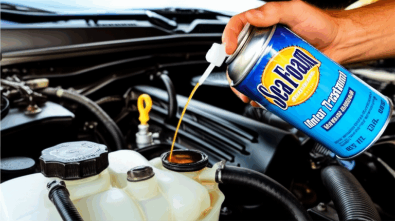
- Keep engine oil fresh on bikes with oil-cooled stators. Clean oil removes heat better and protects insulation varnish on the coils.
- Inspect connectors. Replace toasted stator or regulator plugs with quality parts. Solder and heat-shrink where appropriate.
Oil-Cooled vs Dry Stators
Some engines bathe the stator in oil. Others mount it behind a dry cover. Oil carries heat away from the copper windings and core which can extend lifespan. I’ve measured cooler case temperatures after switching to high quality oil and keeping level correct on oil-cooled designs. Dry stators rely on airflow and conduction through the cover. Either way, cleanliness and tight mounting help heat move out of the coils.
When to Replace vs Rewind a Stator
If testing shows a bad stator you have options.
- Replace with OEM. You’ll usually get the exact output and proper fit. Cost often runs $100 to $500+ depending on model.
- Replace with a quality aftermarket stator. Good suppliers match OEM output and use proper insulating varnish on copper windings.
- Rewind your stator. Some shops can rewind your core. It can save money when OEM parts are scarce. Make sure they use the right gauge wire and quality varnish. Ask about test results and warranty.
I’ve had good luck with OEM and with reputable rewinds. I avoid the cheapest unknown parts because I’ve seen premature failures. Consider the total charging system health. If your regulator failed and cooked the stator then replace both.
Choosing OEM vs Aftermarket Parts
OEM stators usually match the original power curve, wire gauge, and resistance. They fit without fuss. Aftermarket stators vary. Some outperform stock with better copper fill and high temperature varnish. Others cut corners. Read reviews on model-specific forums. Compare specs like per-phase resistance, output ratings at 5,000 RPM, and insulation class.
For the regulator/rectifier I lean toward MOSFET units from known brands. They regulate well and run cooler. Cooler parts last longer.
Upgrades That Actually Help
- MOSFET regulator/rectifier: Reduces heat in the harness and holds voltage steady. Good for bikes with higher loads.
- Better connectors and heavier gauge wires: Replace crusty plugs and thin charging leads. Voltage drop falls and heat drops too.
- Improved cooling to the stator cover: Some riders add ventilation or heat shielding where safe. Check your model’s community for proven tweaks.
- Charging system upgrade kits: Some bikes have well-known weak systems. The aftermarket sometimes offers higher output stators and matching regulators. Balance output with your bike’s wiring capacity.
Quick Troubleshooting Flow You Can Use Today
- Battery check: Test resting voltage after an overnight sit. Around 12.6 to 12.8 V for a healthy lead-acid battery. Load test if you can.
- DC charging test: Start the bike. Rev to 3,000 to 5,000 RPM. Look for 13.5 to 14.5 V at the battery.
- If DC is low: Unplug the stator and test AC output per phase. If AC looks good then suspect the regulator/rectifier or harness.
- If AC is low or uneven: Check stator resistance and ground leakage. If out of spec then the stator is failing.
- Inspect connectors and grounds: Fix any corrosion or heat damage before replacing expensive parts.
- Re-test with known-good parts if you can. Don’t guess if you can measure.
Frequently Asked Questions
What’s the difference between a motorcycle stator and an alternator?
- The alternator is the whole generating system. On many bikes it’s a permanent magnet alternator. The stator is the stationary coil part inside it. People swap the terms and that creates confusion.
How do I know if I have single-phase or three-phase?
- Count the stator wires. Two usually means single-phase. Three equal-color wires usually means three-phase. Your service manual settles it for sure.
Why does my bike only die at idle?
- At idle the stator output is lowest. If the battery is weak and the charging system underperforms the EFI or ignition can drop out at low RPM. Dim headlights at idle are a giveaway.
Can a bad regulator kill a good stator?
- Yes. A failed regulator/rectifier can force the stator to work at max output for too long. Heat cooks the windings and insulation.
What AC voltage should I see from the stator?
- Many bikes show 20 to 70 VAC per phase at idle and 60 to 100+ VAC at 5,000 RPM. Your numbers may differ so check the manual.
What DC charging voltage should I see at the battery?
- Generally 13.5 to 14.5 V with the engine revved. Much lower means undercharging. Much higher means overcharging which points to a regulator problem.
How do I test the stator with a multimeter?
- Measure resistance between phases. Check for no continuity to ground. Measure AC voltage per phase while running. Then check DC voltage at the battery after you reconnect the system.
What causes stator burnout?
- Overheating from high load, poor cooling, corroded connectors, and bad regulation. Cheap rewinds or low quality aftermarket windings can also fail early.
Should I upgrade to a MOSFET regulator?
- I recommend it for many bikes. They run cooler and regulate better which helps stator longevity.
Why does oil matter for oil-cooled stators?
- Oil carries heat out of the windings. Dirty or old oil loses cooling performance. Keep it fresh and at proper level.
Final Thoughts
Once I understood how the stator, flywheel, rectifier, and regulator dance together the charging system stopped feeling like black magic. The stator generates AC when magnets sweep past copper windings. The rectifier flips it to DC. The regulator holds voltage in the charging sweet spot so the battery stays happy and the lights stay bright. That’s it in a nutshell.
If your bike shows dim headlights or starts acting grumpy under electrical load don’t panic. Grab a multimeter and check the basics. Start with the battery. Measure DC charging voltage. Then test the stator for resistance, ground faults, and AC output. You’ll pinpoint the problem faster than swapping parts at random.
A strong charging system makes every ride easier. Keep connectors clean. Keep the battery healthy. Don’t overload the harness. Consider a MOSFET regulator if heat is an issue. If you end up inside the stator cover, take a moment to appreciate the neat engineering in those copper windings and the laminated core that guides magnetic flux. Those thin sheets of steel and that careful winding job quietly power everything from your EFI to your horn while you carve through a favorite backroad.
If you want to dive deeper into how the core materials and laminations influence performance, these resources explain the building blocks behind the scenes:
- The role and construction of stator core lamination
- Why efficient rotor core lamination matters in spinning magnetic fields
- How broader motor core laminations improve efficiency
- A look at the materials behind it all with electrical steel laminations
Ride safe, keep the volts flowing, and may your headlights always shine bright.