How Does a Magneto Stator Work? My Hands-On Guide to Small Engine Power Generation
Table of contents
- Introduction: Why I Care About Magneto Stators
- What a Magneto Stator Is and Why It Matters
- The Anatomy: Stator, Rotor, and Flywheel
- The stator itself
- The rotor or flywheel and its magnets
- The Principle in Action: Electromagnetic Induction in Plain English
- Faraday’s Law made simple
- How changing magnetic flux creates AC voltage
- Single-phase vs three-phase output
- From Spinning Metal to Usable Power: Ignition and Charging
- Ignition system power
- Charging system power
- Voltage regulation and accessories
- Types and Variations You’ll Actually See
- AC vs DC output before rectification
- Different applications and what changes
- Troubleshooting: How I Test a Stator Without Guesswork
- Symptoms of a bad stator
- Resistance and AC voltage tests with a multimeter
- Ground faults and intermittent issues
- Performance, Reliability, and Common Failures
- Heat, insulation, and laminations
- RPM effects and power output
- Moisture, dirt, and wiring problems
- Installation and Maintenance Tips That Save Headaches
- Quick FAQ and My Best Advice
- Conclusion: A Small Part That Carries a Big Load
Introduction: Why I Care About Magneto Stators
I learned to respect magneto stators the hard way. A friend’s motorcycle died on a mountain road at dusk. The lights faded. The battery went flat. We suspected the regulator. It was the stator. Since then I have tested dozens of stators in motorcycles, ATVs, lawn equipment, and small boat motors. I have seen burnt coils. I have traced ground faults. I have watched the flywheel magnets chew up a wiring harness because a grommet wasn’t seated. Every time I fix one I get the same satisfaction. The engine fires. The lights brighten. You feel like you turned a magnetic whisper into real power.
If you want your small engine to start reliably and charge the battery at idle and at high RPM you need to understand the stator. It is the heart of the magneto charging system and the ignition system in many machines. Once you see how simple the principle is you can diagnose issues with a multimeter and a calm head.
What a Magneto Stator Is and Why It Matters
A magneto stator is a set of stationary coils that sits inside your engine cover. The rotor or flywheel with permanent magnets spins around those coils. When magnetic flux changes across the coils the coils generate alternating current. That AC runs the ignition or gets rectified and regulated to charge the battery and power lights.
Two primary jobs stand out.
- Power the ignition system. Exciter coils in the stator feed the CDI or ignition module. The pulse generator coil times the spark at the spark plug.
- Charge the battery and power accessories. Charging coils create AC that goes to a rectifier and a voltage regulator. That system outputs DC to the battery and loads.
If you know what each coil does you can tell if a no-spark problem is ignition related or if a no-charge problem is on the charging side. That knowledge speeds up diagnosis. It also saves money because you avoid shotgunning parts.
The Anatomy: Stator, Rotor, and Flywheel
The stator itself
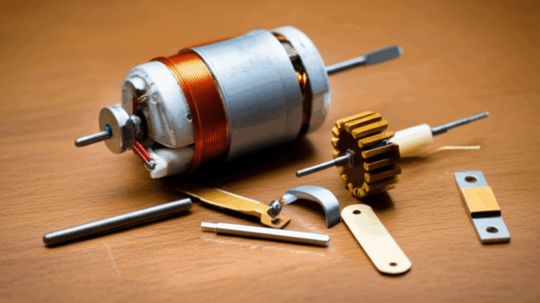
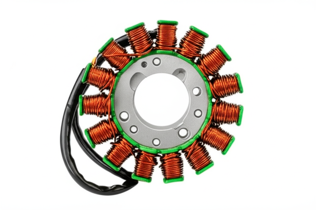
Every stator I open shows three core elements.
- Copper windings. These are the conductors that actually generate current. Windings are counted in turns. More turns give higher voltage at a given speed. Thicker wire supports higher amperage. Some stators have separate charging coils, lighting coils, and exciter coils. Others use a combined three-phase charging stator that feeds everything downstream.
- Laminated iron core. The windings sit on a laminated core. Those thin layers of electrical steel keep eddy currents low and boost efficiency. Laminations matter. They focus the magnetic field into the windings and cut losses from heat.
- Mounting plate or assembly. The stator mounts to the engine case with a set of screws. The harness passes through a grommet. You want that grommet seated. Oil and moisture love shortcuts.
The quality of the stator core lamination directly influences magnetic flux concentration and heat dissipation. Better laminations reduce eddy currents in the stator core. That means higher efficiency and fewer burnt stator coils under sustained high RPM.
The rotor or flywheel and its magnets
The rotor or flywheel carries permanent magnets. These magnets pass over the stator poles. Each pass changes magnetic flux through the coils. That change is what creates voltage. The number of magnetic poles matters. The pole shoe design and magnet placement set the waveform and voltage ripple. The flywheel bolts to the crankshaft. So RPM equals electrical frequency.
The material and build quality of the rotor core count too. A well-built rotor core lamination provides a controlled magnetic path. It helps the magnets deliver consistent magnetic field strength across the stator windings at idle and at redline.
The Principle in Action: Electromagnetic Induction in Plain English
Faraday’s Law made simple
Faraday’s Law says a changing magnetic flux through a coil induces a voltage in that coil. I explain it this way. Imagine the coil as a small toll booth on a highway of magnetic field lines. When more cars pass the booth per second you collect more tolls. When the flywheel spins faster the magnets sweep more flux lines through the coil per second. Voltage rises.
How changing magnetic flux creates AC voltage
As each magnet approaches a stator pole the flux through that coil rises. When it centers the pole the rate of change drops. As it leaves the flux falls in the opposite direction. The waveform swings positive and negative. That is alternating current. If you have multiple poles and multiple coils arranged around the circle you get multiple phases. They are separated by electrical angles. The output phases of the stator combine in a three-phase system for smoother power and higher efficiency.
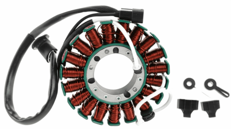
Single-phase vs three-phase output
- Single-phase stator. You will see this in smaller engines and scooters. It is simple. It may run lights directly on AC or feed a basic rectifier-regulator. It can work fine. It can also give dim lights at idle with higher voltage ripple under load.
- Three-phase stator. Common on motorcycles and ATVs with higher electrical loads. Three phases spread the power pulses. The rectified DC has lower ripple. The system supports more wattage at high RPM.
I have measured idle outputs on many machines. A healthy single phase might give 15 to 25 VAC at idle no load. A three-phase stator might give similar per-phase numbers. At 5000 RPM the same system can show 50 to 80+ VAC per phase. Those typical values vary by model and rotor speed. Use OEM specifications when you test.
You will hear terms like electromagnetic induction in stators, induction coil principle, and reluctance. Do not overthink it. The permanent magnet generator stator converts mechanical energy to electrical energy through changing magnetic flux. Laminated cores keep eddy currents low. Copper windings turn that magnetic field into current.
From Spinning Metal to Usable Power: Ignition and Charging
Ignition system power
Most magneto ignition systems rely on two coils in or near the stator.
- Exciter coil. It generates high enough AC voltage for the CDI to charge its capacitor. When the CDI dumps that energy the ignition coil steps the voltage up for the spark plug. No exciter output equals no spark.
- Pulse generator coil or pickup coil. It senses a passing trigger magnet or a notch on the flywheel. That pulse tells the CDI when to fire. Bad timing signal equals misfire or no start.
You may see these labeled as sensing coils or exciter coil stator. Resistance specifications vary. A fault in either coil causes engine stalling or a crank no start with no spark from the ignition system. A multimeter and the service manual make quick work of those checks.
Charging system power
Charging coils produce AC output that runs to a rectifier. The rectifier uses diodes to convert AC to DC. Then the voltage regulator holds system voltage in a safe range for the battery and accessories. Some regulators shunt excess power as heat. Others are series type and run cooler. Either way voltage regulation needs to keep lights stable and the battery healthy.
- Rectifier. Converts AC to DC. Bad diodes cause low voltage output or a dead short that melts wiring.
- Voltage regulator. Maintains stable output. A failed regulator can overcharge a lead-acid battery and boil it. It can also undercharge and strand you at night.
- Battery and loads. After rectification and regulation the system powers accessories like lights. On many bikes the battery charging rate ranges from 0.5 to 20+ amps depending on RPM and system design.
You will see this labeled as charging system stator or battery charging system stator in manuals. The path is simple. Stator AC to rectifier to regulator to battery and loads. If you understand that flow you can find faults without guesswork.
Voltage regulation and accessories
At idle you may see dim lights on a machine that runs lighting coils directly on AC. That is normal for some designs. On a regulated DC system dim or flickering lights often point to low stator output or a bad regulator. Voltage ripple from the stator and rectifier can cause LED flicker. A healthy regulator keeps ripple low. So your lights stay steady.
Types and Variations You’ll Actually See
AC vs DC output before rectification
Every magneto stator produces AC by nature. The DC comes later through a rectifier. You may run certain loads on raw AC in very simple systems. You may run everything on DC on more modern motorcycles. When you hear AC stator vs DC stator someone is usually talking about what the wiring harness expects downstream.
Different applications and what changes
- Motorcycles and ATVs. Often use three-phase stators. They support heated grips, fuel pumps, engine control units, and brighter lighting. They also use CDI units or transistorized ignition. You will see a stator resistance chart and an AC output test procedure in the service manual.
- Lawn mowers and small engines. Often simpler single-phase systems. Some run lights and charge a small battery. Some are pure magneto ignition with no battery.
- Boat motors and snowmobiles. Similar principles with marine grade connectors and different wattage demands. Moisture protection matters.
- Scooters, chainsaws, weed eaters, and kart engines. Stators scale down. The physics stays the same.
You will also meet magneto vs alternator debates. In common shop talk a magneto uses permanent magnets on the flywheel with coils on the stator and creates power without a field coil. Many motorcycle “alternators” are permanent magnet alternators. They work like magnetos. Traditional automotive alternators use an electromagnet rotor and can regulate output by changing field current. The stator vs rotor function remains. One stays still. One spins. The method of creating the magnetic field changes.
Troubleshooting: How I Test a Stator Without Guesswork
Symptoms of a bad stator
These crop up again and again.
- Battery not charging. The engine runs off the battery until it dies. Your lights dim. The bike stalls when you slow down.
- No spark from ignition system. The engine cranks forever. The spark plug stays silent.
- Dim or flickering lights. Voltage dips at idle. Lights brighten with RPM. Sometimes they flicker at steady RPM. That can be stator or regulator.
- Intermittent charging. It charges at times. It quits when hot. It returns when cool. That points to insulation breakdown or a loose connector.
- Burnt stator coils. You smell it. The windings look dark. Insulation looks baked. That stator needs replacement.
Resistance and AC voltage tests with a multimeter
I always start with a visual inspection. I look for dirt and debris in the flywheel cover. I check the wiring harness connections and the rubber grommet. Oil or water in the connector points toward a ground fault or porous insulation. Then I test with a multimeter.
- Resistance between stator leads. Unplug the stator from the harness. Set your multimeter to ohms. Check between each pair of leads on a three-phase stator. Typical good readings run 0.1 to 1.0 ohm. Compare to OEM specifications. High resistance points to an open circuit. Near zero suggests a short circuit.
- Resistance from each lead to ground. This should read open loop or infinite. Any measurable resistance indicates a ground fault in the stator or a pinched wire. A ground fault kills output.
- AC voltage output. With the stator unplugged and the engine running measure AC voltage across leads. At idle you might see 15 to 25 VAC per phase. At 4000 to 5000 RPM you might see 50 to 80+ VAC per phase. The numbers vary by design and rotor speed. You want balanced readings across phases. A weak phase points to a coil problem.
For a simple single-phase stator you do the same style of tests. One pair of wires. One set of readings. When you test the pulse generator coil use resistance specs from the service manual. The pulse coil often measures in the hundreds of ohms. The exciter coil might measure higher. I do not guess. I look up specifications.
Ground faults and intermittent issues
Intermittent charging usually involves heat. Heat expands metal. That tiny break in a winding opens. The engine cools. The circuit closes. Output returns. Moisture can create a temporary ground fault with dirt acting like a conductive bridge. I sometimes warm the stator gently with a heat gun while watching the meter. The reading drifts. That confirms heat-related stator degradation over time.
Performance, Reliability, and Common Failures
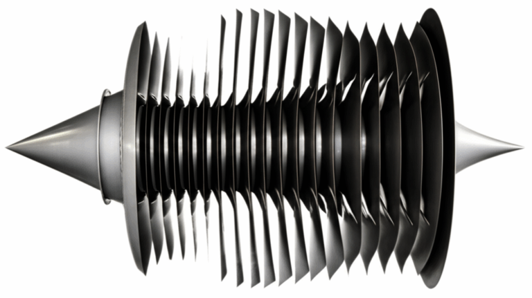
Heat, insulation, and laminations
Stators live in harsh conditions. There is oil mist. There is vibration. There is heat. The laminated core is your friend. Laminations made from quality electrical steel improve efficiency and cut heat. Better laminations mean fewer eddy currents and less temperature rise under load. If you want to nerd out on materials you can skim the basics of electrical steel laminations. You will see why thin laminations and good insulation between layers matter.
Common failure modes are well known.
- Open circuit. A coil wire breaks. That phase drops out. You get no charge or weak output. Vibration and poor strain relief start the crack.
- Short circuit. Insulation breaks down between turns. Current bypasses part of the coil. Output falls. The stator overheats.
- Ground fault. The winding or a terminal touches the core or engine ground. Output collapses. You may pop a fuse or cook the regulator.
- Overheating and burnt coils. Sustained overload and bad voltage regulation roast insulation. Once insulation chars the stator is done.
RPM effects and power output
Rotor speed directly affects magnetic flux change rate. Voltage rises with RPM. Power output depends on both voltage and current. As RPM climbs the stator can deliver more wattage until it hits the design limit. The regulator clamps voltage. The excess gets shunted as heat in a shunt regulator. Some bikes run hot in the charging system at high RPM for long periods. That heat shortens stator lifespan. I watch for brown connectors and baked plugs on wiring harness connections. Those brown plugs speak volumes.
Voltage ripple and power curves show up in oscilloscope traces. Most of us do not need that level of analysis. If your multimeter shows stable AC per phase and the DC system holds a steady 13.8 to 14.5 volts at the battery with lights on you are in good shape.
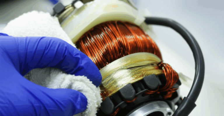
Moisture, dirt, and wiring problems
Moisture does not play nice with insulation. Dirt and debris score the flywheel and chew on wires. I have pulled covers packed with mud on ATVs. That mud traps heat. Heat accelerates insulation breakdown. A quick cleaning and proper stator ventilation make a bigger difference than people think.
Do not forget connectors. A corroded connector adds resistance. That resistance wastes power as heat. A heated terminal loosens the spring tension in the female side. It then runs even hotter. You get a feedback loop that melts plastic. Clean and protect connectors. Replace terminals that look cooked.
Installation and Maintenance Tips That Save Headaches
- Use OEM specifications. Stator winding count, wire gauge, and pole shoe design vary. So do torque settings for the flywheel and stator mounting plate. Follow the book. The right torque keeps the flywheel from walking on the crank taper.
- Inspect the flywheel magnets. Weak or damaged magnets hurt magnetic field strength. That lowers output. If the flywheel has cracked magnets replace it. Do not take chances.
- Route the harness carefully. Keep it off sharp edges. Use grommets. A pinched wire creates a ground fault and a short circuit.
- Clean mounting surfaces. A stator that does not sit flat vibrates. Vibration cracks wires. Clean the crankcase boss and the back of the stator plate.
- Use quality parts. Better laminations and insulation last longer under heat. If you want to understand the manufacturing basics that impact reliability you can browse motor core laminations. It gives helpful context on why laminations and materials matter in any electromagnetic core.
- Test the regulator-rectifier. A new stator will die early if the regulator fails. A failed shunt regulator may overload the stator. Replace both if you see a pattern of repeat failures.
- Check loads. Add-on lights and accessories increase electrical loads on the stator. Make sure your wattage stays within what the charging system can support. If your bike needs more, upgrade the stator and the regulator as a matched set.
Quick FAQ and My Best Advice
How does a generator stator work compared to a magneto stator
Both use electromagnetic induction in stators. The difference is how the magnetic field is created. A magneto uses permanent magnets on the rotor or flywheel. A traditional alternator or generator might use an electromagnet rotor. Either way the stator harvests energy from changing magnetic flux.
What are the signs of a bad stator
Classic symptoms include no charge, dim lights, intermittent charging, and no spark from ignition system when the exciter coil fails. Burnt stator coils are easy to spot. A ground fault shows up as continuity from a stator lead to engine ground.
How do I test a stator coil with a multimeter
Unplug it. Measure resistance between leads and to ground. Compare to OEM resistance specifications for your stator winding count and design. Then measure AC voltage output at idle and at 4000 to 5000 RPM. For many bikes 15 to 25 VAC per phase at idle and 50 to 80+ VAC at high RPM are typical. Your service manual is the authority.
What causes stator failures
Heat and vibration top the list. Poor voltage regulation stresses the windings. Oil contamination wicks into insulation. Moisture and dirt speed corrosion. A short circuit or a ground fault finishes the job.
Should I choose OEM or aftermarket
I check reviews and specifications. High-performance stators can offer better copper fill and improved insulation. OEM matches the bike’s power curves and reliability factors. Either can work if the magnetic field strength and laminations meet spec.
How does rotor speed affect output
Faster rotor speed increases the rate of change of magnetic flux. That raises voltage. The regulator clamps DC voltage to protect the battery. That is why the stator and regulator can run hot at high RPM with low electrical load.
Can I run LED lights and added accessories
Yes within limits. Understand your wattage and amperage budget. Charging rate after rectification must cover the loads. If you see battery discharge at idle your loads exceed output at that RPM. Consider a three-phase upgrade if your platform allows it.
Is a three-phase stator better
For higher loads yes. Three-phase offers smoother DC after rectification and lower voltage ripple. It handles accessories better. Single-phase works fine for simpler setups.
What does laminated core mean and why does it help
The stator core uses thin sheets of steel with insulation between them. Laminated core benefits include reduced eddy currents in the stator core and lower heat. You get better efficiency and longer life.
What role does the pulse generator coil play
It tells the CDI when to fire. Without it the engine loses timing and may not spark at all.
What about testing the CDI
CDI diagnostics vary. Many require substitution with a known good unit. I confirm the stator exciter output and the pulse generator signal first. If both test good I suspect the CDI.
What is a ground fault in a stator
It is when a winding or a wire touches the stator core or engine ground. That creates a short to ground. It kills or weakens the output. It often shows up as a measurable resistance from a stator lead to ground.
Conclusion: A Small Part That Carries a Big Load
A magneto stator looks humble. It is just copper windings on a laminated core with a wire pigtail. Yet it turns spinning magnets into the electrical energy that lights the road and fires the spark plug. Faraday’s law does the heavy lifting. The flywheel magnets deliver changing magnetic flux. The coils turn that change into AC. The rectifier and voltage regulator tidy it up for the battery and accessories.
When I troubleshoot I follow a simple script. Inspect. Measure resistance. Check for ground faults. Measure AC voltage at idle and at RPM. Verify rectifier and regulator function. If the numbers miss OEM specifications I do not guess. I replace the failed part and fix the cause. Sometimes that means a new stator. Sometimes it means a new regulator-rectifier. Sometimes it means cleaning a connector and rerouting a harness that rubbed on the case.
If you remember nothing else remember this. A stator is a simple device that rarely hides its problems. Use Faraday’s law as your compass. Use your multimeter as your map. Pay attention to heat and laminations. Choose quality parts that handle magnetic fields well. If you want to see how lamination stacks influence cores in general the overview on core lamination stacks gives helpful context across many electromagnetic assemblies.
With that you can keep your engine charging. You can keep your spark hot. You can keep your ride reliable for years.
Key concepts I covered and how they connect in practice
- Magneto operation principles and how a magneto generates current through electromagnetic induction.
- The stator function explained with copper windings, laminated core, and mounting.
- The rotor or flywheel magnets create the magnetic field. Rotor speed effects matter for output.
- Magnetic flux changes induce alternating current in stators. That leads to AC voltage output.
- Single-phase stator vs three-phase and how each affects voltage ripple and power curves.
- Charging coils feed a rectifier and a voltage regulator. That system maintains stable output for the battery and accessories.
- Exciter coils and pulse generator coil feed the ignition system and the CDI unit. That produces spark at the right time.
- Common stator failures include open circuits, short circuits, ground faults, and burnt coils from insulation breakdown.
- Testing uses a multimeter for resistance specifications and AC voltage specifications at idle and at higher RPM. Stator AC output test procedure is straightforward.
- Stator core construction and laminated core benefits limit eddy currents. Better lamination and insulation improve efficiency and stator reliability factors.
- Maintenance tips cover wiring harness connections, moisture damage, dirt and debris, stator ventilation, and proper stator torque settings.
If you apply these ideas you will diagnose charging issues with confidence. You will fix no-spark problems faster. You will understand why a laminated core and strong magnets matter. That knowledge saves time and keeps you on the road.