How Do Rotors and Stators Work? The Core Principles of Electric Motors and Generators
Table of contents
- I. Why rotors and stators clicked for me
- II. What is a stator? The stationary powerhouse
- A. Stator core and laminations
- B. Stator windings and magnetic fields
- III. What is a rotor? The rotating core
- A. Rotor types: squirrel cage, wound rotor, and permanent magnet
- B. Rotor bars, windings, and magnets in action
- IV. The physics that make it all work
- A. Faraday’s Law and electromagnetic induction
- B. Lorentz force and the motor effect
- C. Rotating magnetic fields and why rotation begins
- V. Motor mode: how electrical energy becomes mechanical energy
- A. AC induction motors
- B. Synchronous motors and BLDC motors
- C. DC motors with commutators and brushes
- VI. Generator mode: how mechanical energy becomes electrical energy
- VII. Key differences across machine types
- A. AC induction motors
- B. Synchronous motors and generators
- C. DC motors and generators
- D. Stepper, servo, universal, and linear motors at a glance
- VIII. The “hidden” heroes: air gap, bearings, housing, and cooling
- IX. Materials and design choices that make or break performance
- A. Electrical steel, laminations, and core design
- B. Magnets, copper vs. aluminum, and core losses
- C. Toward higher IE efficiency classes
- X. Real‑world applications and why this matters
- XI. Common questions I hear and how I explain them
- A. Why does the rotor actually move
- B. What is back EMF and why should I care
- C. What is slip in an induction motor
- XII. Reliability, protection, and smart monitoring
- XIII. Final thoughts
I. Why rotors and stators clicked for me
I still remember the first time I took apart an old desk fan. I expected a mess of mystery parts. Instead I found two main characters locked in a tight dance. A stationary ring with copper coils around the inside and a core that spun freely in the middle. That pair taught me a lesson I keep coming back to. If you understand the stator and the rotor you can understand almost every electric motor and generator on the planet.
Over the years I have worked with AC induction motors in pumps and conveyors. I have spec’d brushless DC motors for robots and fans. I have repaired alternators. The story never really changes. The stator sets the stage with a magnetic field and the rotor responds with motion or voltage. That simple interplay turns electricity into motion or motion into electricity. Let’s unpack how it really works in plain language.
II. What is a stator? The stationary powerhouse
The stator is the stationary part of a motor or generator. Think of it as the sturdy ring that surrounds the action. It holds the steel core and the copper windings. When you energize those coils the stator produces a magnetic field. In motors that field can be fixed in space or it can rotate in a circle. In generators the stator holds the windings where voltage is induced when the rotor moves.
A. Stator core and laminations
Inside the stator sits a core made from thin steel sheets called laminations. Manufacturers stack those sheets and press them into a rigid ring with slots for the copper windings. This laminated construction reduces unwanted heating from eddy currents and hysteresis. I have seen cheap motors with poor laminations run hot and waste power. I have also seen premium cores shave watts off losses and run cool.
If you want to dive deeper into the material choices behind these cores you can read about stator core lamination. The quality of that lamination stack matters a lot. Good steel and smart stacking keep losses low and efficiency high.
B. Stator windings and magnetic fields
Windings are coils of insulated copper wire placed in the stator slots. When current flows through a coil a magnetic field appears around it. Arrange several coils and energize them with coordinated currents and you can create a magnetic field that rotates around the stator. Three‑phase AC does this beautifully. Each phase lags the next by 120 degrees. The combined effect is a magnetic field that spins smoothly. That rotating field is the secret sauce behind most industrial motors.
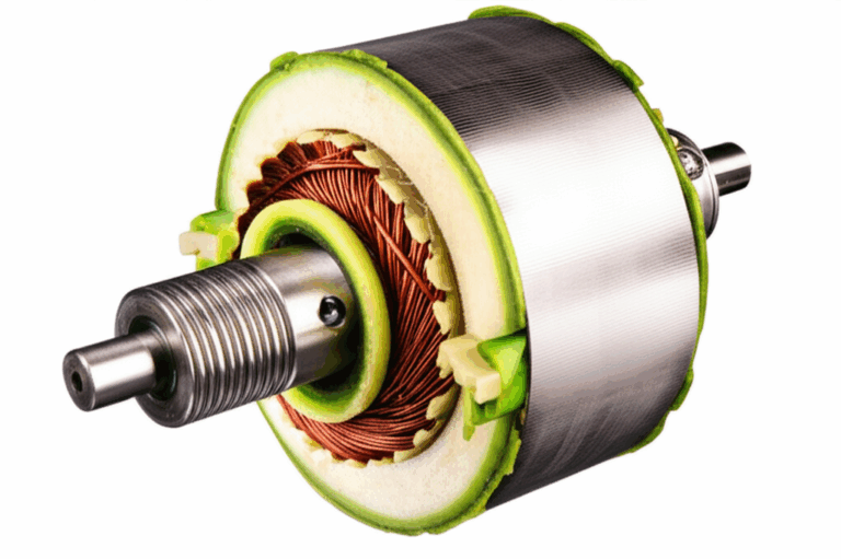
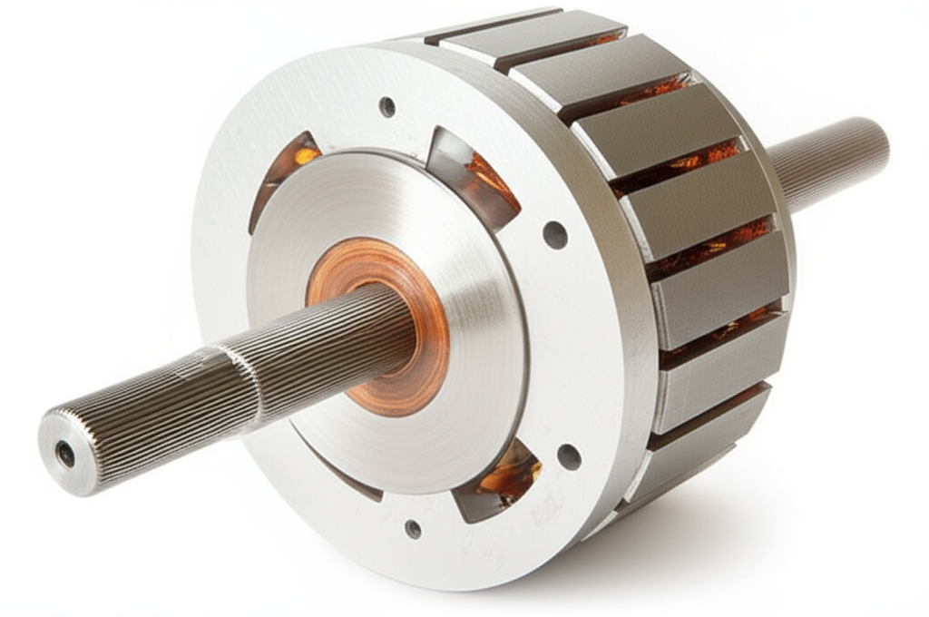
III. What is a rotor? The rotating core
If the stator is the stage the rotor is the dancer. It sits on bearings and spins inside the stator’s bore. The rotor carries its own steel core and either conductors or magnets. Its only job is to interact with the stator’s field to create torque in a motor or to cut magnetic flux and induce EMF in a generator.
A. Rotor types: squirrel cage, wound rotor, and permanent magnet
- Squirrel cage rotors: These live inside most AC induction motors. The rotor carries bars of conductive metal connected by end rings. No brushes. No electrical connection to the outside. Simple and tough.
- Wound rotors: These carry actual windings on the rotor with slip rings that bring current in or out. You see them less often now yet they still make sense for some starting and control needs.
- Permanent magnet rotors: These use magnets instead of rotor windings. You find them in brushless DC motors and many synchronous machines. Strong magnets deliver high torque and high efficiency.
B. Rotor bars, windings, and magnets in action
Rotor design shapes how the machine behaves. I like to think of it as personality. A deep‑bar squirrel cage gives strong starting torque. A skewed rotor cuts down noise and torque ripple. Wound rotors can insert resistance at start to control current. Permanent magnets slam you with torque at low speed which is why EVs love them.
If you want to see how steel and slots come together on the spinning side this overview of rotor core lamination is a good reference. Rotor laminations fight the same eddy current battles as stators and careful geometry makes the torque smooth.
IV. The physics that make it all work
Once you see the parts the physics starts to feel less mysterious. Two principles do almost all the heavy lifting.
A. Faraday’s Law and electromagnetic induction
Michael Faraday showed that a changing magnetic field induces a voltage in a conductor. Spin a coil through a magnetic field and the flux it sees changes. Voltage appears. That is a generator in one sentence. Push magnetic field through a stationary coil and change it with time. You also get voltage. Motors exploit this too because changing fields show up everywhere inside them.
B. Lorentz force and the motor effect
A current‑carrying conductor placed in a magnetic field feels a force. That is the Lorentz force. In a motor that force acts on rotor conductors. The direction follows a right‑hand rule. Current and magnetic field form two fingers and force stands as the thumb. It is a neat party trick with magnets and wire. It is also why your washer drum spins when current flows.
C. Rotating magnetic fields and why rotation begins
Here is the part that clicks for most people. If the stator generates a rotating magnetic field the rotor tries to align with it. In an induction motor the stator field races ahead which induces currents in the rotor bars. Those new rotor currents create their own magnetic fields which push against the stator field. The rotor chases the stator field. It never quite catches up which we call slip. In a synchronous motor the rotor uses magnets or DC field windings so it locks step with the stator field and spins at the same speed.
V. Motor mode: how electrical energy becomes mechanical energy
In motor mode electricity goes in and rotation comes out. The path differs a bit by type so I will lay out the common families I deal with most.
A. AC induction motors
- Stator: Three‑phase currents create a rotating magnetic field at the synchronous speed. That speed depends on AC frequency and the number of magnetic pole pairs. Raise the frequency with a variable frequency drive and the field spins faster and the motor speeds up.
- Rotor: The rotating field cuts the rotor bars which induces currents. Those currents set up their own fields. The rotor sees torque that pulls it along.
- Slip: The rotor must lag the rotating stator field to keep inducing current. That gap in speed is slip. High slip at startup and small slip at rated speed. More load means more slip which gives more torque to balance the load.
- Squirrel cage vs wound rotor: Squirrel cage is simple and rugged. Wound rotor allows resistance control during start which tames current and boosts torque.
- Why industry loves them: They are efficient and cheap and predictable. They run pumps, fans, compressors, and conveyors all day. Add a VFD and you get smooth speed control and soft starts that save belts and couplings.
B. Synchronous motors and BLDC motors
- Synchronous motors: The rotor’s field is created by DC windings or permanent magnets. The rotor locks to the rotating stator field. No slip in steady state. These can correct power factor in some plants and deliver precise speed.
- Brushless DC (BLDC) motors: These are synchronous machines that use permanent magnets on the rotor and electronic commutation on the stator windings. You get high efficiency and great power density. Many BLDC designs top 90 percent efficiency and premium designs push into the mid 90s. That is one reason you see them in drones fans and electric vehicles.
- Control: In BLDC and permanent magnet synchronous motors the electronics measure rotor position with sensors or estimators. Then they time the current so the stator field stays a quarter turn ahead of the rotor’s magnets. Think of it like a friend pulling you along with a rope. They always tug at just the right angle so you keep moving smoothly.
C. DC motors with commutators and brushes
- Stator: A fixed magnetic field from permanent magnets or field windings.
- Rotor (armature): Carries windings. Current flows into them through brushes that press on a segmented ring called a commutator. As the rotor turns the commutator switches which coils get energized. The result is a steady torque in one direction.
- Back EMF: As the rotor spins it generates a voltage that opposes the supply. That is back EMF. At higher speed back EMF rises which reduces current and keeps the motor from running away. It also makes speed roughly proportional to applied voltage in simple DC motors.
VI. Generator mode: how mechanical energy becomes electrical energy
Flip the script. Feed mechanical power into the shaft and electricity comes out. Wind turbines spin the rotor with wind. Hydroelectric plants spin with falling water. Engines spin alternators in cars. The rotor carries magnets or energized windings that sweep past stator coils. Flux through those coils changes which induces voltage. Hook the stator to a load and current flows.
In a synchronous generator the rotor spins at a speed that matches grid frequency and pole count. Operators control the rotor’s field current to set the output voltage and reactive power. In an induction generator the rotor is driven a bit faster than the stator field created by the grid. That reversal of slip pushes power back into the grid. Small wind and micro hydro sometimes use induction generators because they are robust and simple.
VII. Key differences across machine types
A. AC induction motors
- Stator: Creates a rotating magnetic field.
- Rotor: Squirrel cage or wound. It always slips behind the stator field so it can generate torque.
- Pros: Rugged and cost‑effective. Simple to maintain. Great for pumps and fans.
- Cons: Lower efficiency than premium permanent magnet machines in some ranges. Power factor needs help without VFD or capacitors.
B. Synchronous motors and generators
- Stator: In motor mode it creates a rotating field. In generator mode it collects induced current from moving rotor magnets or windings.
- Rotor: Permanent magnets or DC field windings. It locks to the stator field.
- Pros: Precise speed and great efficiency. Strong at power factor correction in big plants. Perfect for alternators.
- Cons: Needs a starting method if not self‑starting. Electronics or excitation systems add complexity.
C. DC motors and generators
- Stator: Permanent magnets or field windings. Field is fixed in place.
- Rotor: The armature carries current and the commutator switches it.
- Pros: Simple speed control with voltage and great low‑speed torque.
- Cons: Brushes wear. Commutators arc. Maintenance adds up.
D. Stepper, servo, universal, and linear motors at a glance
- Stepper motors: Move in precise steps by energizing stator phases in sequence. They hold position without feedback at low speeds which makes them great for 3D printers and small CNCs.
- Servomotors: Usually permanent magnet synchronous or BLDC with feedback sensors. They deliver exact torque and position under closed‑loop control.
- Universal motors: Run on AC or DC. High speed and high noise. You find them in drills and some appliances.
- Linear motors: Unroll the stator and rotor to get straight‑line motion. Maglev trains take this idea to an extreme.
VIII. The “hidden” heroes: air gap, bearings, housing, and cooling
The air gap is the tiny space between rotor and stator. Typical gaps range from fractions of a millimeter in small motors to a couple millimeters in larger ones. Shrink the gap and magnetic coupling strengthens which boosts torque per amp and efficiency. Shrink it too much and the rotor can rub the stator during thermal growth or vibration. Precision machining pays off here.
Bearings carry the rotor with low friction. Good alignment and lubrication reduce losses and extend life. Housing and frames protect the windings and provide paths for heat to escape. Cooling can be simple airflow or forced liquid cooling in high power machines. I have seen motors fail not from electrical issues but from heat and contamination. Keep them cool and clean and they will run for years.
IX. Materials and design choices that make or break performance
A. Electrical steel, laminations, and core design
Core losses come from changing magnetic fields inside steel. Laminations minimize eddy currents because thin insulated sheets block sideways currents. Material grade matters. Higher silicon content reduces losses yet affects magnetization. Designers juggle thickness, alloy, and stacking factor to hit efficiency and cost targets.
If you want a broader view of the stack that sits at the center of every motor take a look at motor core laminations. You will see how stator and rotor stacks align in purpose. The metal and the geometry keep losses low so the windings can do their work without wasting energy.
Engineers often start with the steel itself. Grain‑oriented versions help transformers. Non‑oriented electrical steels serve motors where flux rotates. If the metallurgical side interests you this explainer on electrical steel laminations shows why the base sheet matters as much as the final stack.
B. Magnets, copper vs. aluminum, and core losses
Permanent magnets changed the game. Neodymium magnets can create fields far stronger than ferrites. Designers shrink the rotor and lift the torque density. That is why modern EV traction motors can pack 100 kW or more into surprisingly small packages. Copper makes great windings thanks to low resistive losses. Aluminum works in rotor bars thanks to casting ease and cost. I have seen aluminum bars serve for decades in big fans. Copper can give a bit more efficiency and starting torque but cost and weight matter too.
Core losses break into hysteresis loss and eddy current loss. Thin laminations and good steel cut both. You will also hear about magnetic flux density. Run too high and the core saturates which hurts torque per amp and efficiency. Design is a balancing act. Push flux to shrink the motor or pull back to save energy and heat.
C. Toward higher IE efficiency classes
Efficiency standards keep rising across the world. IEC lists IE1 through IE5 from standard to ultra premium. Many regions require IE3 or better for new motors. Hitting those classes requires tight air gaps careful lamination stacks smart winding layouts and low‑loss bearings. Drives help too because they match motor speed to load. I have watched facilities cut power bills by swapping fixed‑speed motors on fans to VFD controlled units that ramp down when demand drops. Less noise. Less wear. Quick payback.
X. Real‑world applications and why this matters
Here is the scale that stunned me when I learned it. Electric motors consume nearly half of the world’s electricity. In many industrial plants motors take 70 to 80 percent of total power. That single fact explains why small gains in rotor‑stator design echo through energy bills and carbon footprints.
Everyday life runs on these machines. Your refrigerator compressor. The fan in your laptop. The pump moving water in your building. Industry leans on motors for pumps compressors mixers conveyors and robots. Transportation switched gears as EVs went mainstream. Most EVs use permanent magnet synchronous motors or AC induction motors. Power outputs range from tens of kilowatts to several hundred. Peak efficiencies often sit above 90 percent and top designs cross 95 percent in sweet spots. Thermal management and magnetic design make that possible.
Power generation tells the same story from the other side. Wind turbines use generators with permanent magnet or doubly fed induction designs. Hydroelectric plants spin massive synchronous generators. Behind each machine sit the same two players. A stator that carries windings and a rotor that brings the changing field.
Air gap optimization deserves a special note. Typical gaps run from 0.2 mm in small motors to a couple millimeters in larger units. Tighter gaps improve magnetic coupling and power factor. They demand better machining and alignment. The payoff is real. Precision in that one dimension often separates standard motors from premium ones.
Smart motors keep growing too. Plants now embed sensors that watch temperature vibration and current in real time. Predictive maintenance catches rotor imbalance or stator insulation breakdown before downtime hits. The market for smart motors has been growing steadily because uptime and efficiency pay for themselves.
XI. Common questions I hear and how I explain them
A. Why does the rotor actually move
I ask people to picture a compass needle near a rotating magnet. The magnet’s north pole sweeps around. The needle swings to follow. In an induction motor the rotor does not have a permanent magnet yet currents appear in the rotor bars which create a magnetic field. That induced field wants to align with the stator’s field so torque appears. The rotor chases the moving magnetic target. In a synchronous motor the target and the chaser lock together so they spin in sync.
B. What is back EMF and why should I care
Spin a motor and it acts like a generator. It produces a voltage that opposes the applied voltage. That is back EMF. At low speed back EMF is small so current rises and torque is strong. At high speed back EMF grows and current falls if you hold the same supply voltage. This natural feedback keeps DC motors from running away and it shapes speed control strategies. It also shows up in BLDC control where the controller measures back EMF to estimate rotor position.
C. What is slip in an induction motor
Slip is the difference between the stator’s rotating field speed and the rotor speed. If the stator field spins at 1800 rpm and the rotor spins at 1740 rpm the slip is 60 rpm. No slip means no induced rotor current which means no torque. More load means more slip until torque balances the load. Too much load and the motor cannot keep up so the speed falls and the motor overheats. VFDs help by raising voltage and frequency together which keeps flux optimal and torque available across a wide speed range.
XII. Reliability, protection, and smart monitoring
When motors fail I usually find one of a few culprits. Overheating cooks insulation. Bearings wear or starve for grease. Vibration loosens everything. Voltage imbalance or overvoltage stresses windings. Moisture attacks insulation. Simple steps avoid most headaches. Keep things clean and cool. Align shafts and couplings. Use proper overload protection and soft starts. Monitor current and temperature.
Smart sensors changed the maintenance game in places I have worked. Vibration analysis catches rotor imbalance or bearing defects early. Thermal sensors flag cooling problems. Partial discharge testing and insulation resistance checks catch stator insulation breakdown before a short turns into smoke. Predictive maintenance keeps motors in service rather than on the repair bench.
XIII. Final thoughts
After years of building, selecting, and fixing motors I keep coming back to one simple idea. The stator shapes a magnetic field and the rotor responds. Motors turn electricity into motion. Generators turn motion into electricity. Everything else is nuance and optimization.
When you choose materials wisely and minimize core losses you lift efficiency. When you tighten the air gap you boost torque density. When you match control to machine physics you squeeze out wasted energy. Want to go deeper on materials? These primers on stator core lamination, rotor core lamination, and motor core laminations lay out the building blocks. If you are curious about base steels this quick guide to electrical steel laminations shows why those thin sheets matter so much.
Big picture. Electric motors use 45 to 50 percent of the world’s electricity and far more inside factories. That scale makes every percent of efficiency worth chasing. It also makes rotors and stators the quiet heartbeat of modern life. Learn how they work and you can spot them everywhere. You will hear the hum of a fan and you will know exactly which two parts make that melody.