Electrical Steel Laminations: What I Learned Building Better Motors and Transformers
Table of contents
- Introduction: Why laminations matter in the real world
- The physics that actually move the needle
- Materials I’ve used and why they worked
- Picking laminations for electric motors
- Stator cores: slots, teeth, and the stack
- Rotor cores: cages, magnets, and saturation
- BLDC and PM machines: what bit me and what fixed it
- Stack building: punching, laser cutting, bonding, and burrs
- Coatings, insulation, and stacking factor
- Winding and thermal realities you can’t ignore
- Transformer cores: EI, UI, step-lap, and hum control
- Quality control that saved me money and time
- Manufacturing trade-offs that change the outcome
- Common mistakes I made and how I solved them
- Cost versus performance: how I justify the spec
- A practical selection checklist you can reuse
- Final thoughts
Introduction: Why laminations matter in the real world
When I built my first motor core I treated the laminations like an afterthought. Steel is steel right. I learned fast that it isn’t. The right electrical steel and the way you stack it changes everything. Heat. Noise. Efficiency. Even how the motor feels when it pulls under load.
The same story played out with transformers. I once shipped a prototype that met voltage under no-load yet ran hot and buzzed under load. The fix wasn’t a different winding pattern. The fix started with better core material and a smarter stack.
In this guide I’ll share what I learned the hard way. I’ll break down how laminations work. I’ll walk through material choices. Then I’ll connect that to stators, rotors, and transformer cores you can actually build and ship. If you’re choosing between grades, thicknesses, coatings, and manufacturing methods you’re in the right place.
The physics that actually move the needle
I keep three loss mechanisms in my head when I design with laminations. Hysteresis loss. Eddy current loss. And mechanical loss from magnetostriction and vibration.
- Hysteresis loss comes from cycling the magnetic domains. It scales with frequency and with the area of the B-H curve. Narrower B-H curve better. Lower loss at the same flux. Alloy and heat treatment matter here.
- Eddy current loss comes from loops of current induced in the steel. Thin laminations cut those loops. Good interlaminar insulation helps. Eddy loss rises roughly with the square of thickness and frequency. That pushes me to thinner material for high-speed motors or high-frequency transformers.
- Magnetostriction drives hum and hiss. It changes dimension as it magnetizes. Bad joints and loose stacks turn that into noise and heat. I always think about mechanical clamping along with magnetic path.
Then there’s saturation. If I drive the flux density B too high I get a cliff. Inductance collapses and the core soaks up current. Motors lose torque per amp and heat up. Transformers sag and buzz. I aim for a peak flux that keeps margin under worst case conditions. High ambient. Tolerance stack-ups. Coil heat. Real loads rarely match the textbook.
Materials I’ve used and why they worked
I group choices into three buckets. Grain-oriented silicon steel. Non-grain-oriented silicon steel. And specialty alloys.
- Grain-oriented silicon steel (CRGO) shines in transformers with a dominant direction of flux. It gives low core loss along the rolling direction. It isn’t ideal for motors since motor flux rotates. I use CRGO for power transformers and chokes with a steady flux direction.
- Non-grain-oriented steel (CRNGO) works for rotating machines. Flux sweeps around the stator and rotor. CRNGO gives more uniform properties in all directions. I pick the grade and thickness based on speed, frequency, and efficiency targets.
- Thickness picks matter. 0.5 mm makes sense for low frequency, low cost. 0.35 mm or 0.3 mm helps at higher speed or where every watt counts. I’ve used 0.2 mm for serious high-speed work and the cost curve climbs fast.
- Coatings matter more than I first thought. The interlaminar insulation reduces eddy currents between sheets. It also sets how the stack bonds and how it tolerates heat and varnish. I match the coating to my bonding method and my bake schedule.
The umbrella category often called electrical steel laminations covers these families. I look at core loss curves at my operating flux and frequency. I compare permeability, coating class, and thickness. Then I talk to the stamping house about burr and flatness. The datasheet sets the ceiling yet the process sets the floor.
Picking laminations for electric motors
Stator cores: slots, teeth, and the stack
The stator is where I feel the trade-offs the most. Slot shape sets copper fill and thermal path. Tooth width and yoke thickness set saturation. Skew and step in the lamination pattern change torque ripple and noise.
Here’s what I do now.
- I start from slot fill and thermal. If I can’t get copper in cleanly nothing else matters. I keep a realistic fill factor. Insulation, slot liners, and winding heads eat space. I leave margin.
- I check tooth flux density at peak current. I run finite element analysis when I can. I still sanity check with area times flux numbers on the back of a napkin. If the tooth saturates I widen it or raise stack height.
- I plan skew early. A distributed skew across a few laminations reduces cogging and torque ripple. It can extend build time and cost. I’ll use partial skew if I need a compromise.
- I pick a lamination thickness that fits my speed. Higher electrical frequency needs thinner laminations. That is true in induction machines and PM machines. I look at iron loss at my maximum speed not just rated speed.
- I work the stack factor into my geometry. You never get 100 percent dense metal. Coating, burr, and bonding reduce effective cross section. I use a realistic stacking factor in my magnetic calculations.
If you are new to stator design start with a proven tooth and slot ratio. Then tune the slot opening for your winding method. Talk to your lamination supplier about what slot opening and bridge widths they can hold repeatably.
When I tightened tolerances on the stator core lamination I saw a clean drop in torque ripple. The slot-to-slot repeatability improved the back EMF waveform. The motor ran quieter at the same load. That single change saved me more than any control algorithm tweak I tried before it.
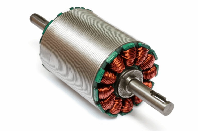
Rotor cores: cages, magnets, and saturation
Rotors make or break the design. Squirrel cages want deep bars or double cages for starting torque. PM rotors want bridges and ribs that support magnets without choking the flux.
A few lessons that stick with me.
- Don’t starve the rotor back. That thin band behind the magnets or bars saturates first. If it saturates your torque-per-amp falls off. I protect that section in my layout and I test it at overcurrent.
- Skew helps here too. A skewed rotor reduces cogging and acoustic noise. It often complicates manufacturing. I weigh the benefit against the stacking and balancing effort.
- Watch for flux leak across magnet bridges. Bridges add mechanical strength yet they create a parallel path. I shape them to limit leakage. Finite element analysis earns its keep here.
- Balance the rotor early. Even small asymmetries in magnet glue or bar fill can shake the machine apart at speed. I plan balance features in the core before I cut steel.
Refining the rotor core lamination layout gave me a cooler rotor at high load. That helped the magnets stay under their temperature limit. The motor kept its torque and didn’t drift in performance after long duty.
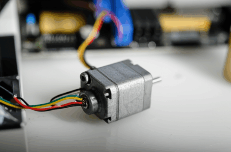
BLDC and PM machines: what bit me and what fixed it
BLDC motors look simple on paper. Three phases. Magnets. Commutation. The devil hides in the lamination geometry.
What bit me first was slotting. I had a sharp slot opening that increased harmonics in the back EMF. The motor sang at certain speeds. I softened the opening and added a slight skew. That pushed the noise out of the most audible range. It also smoothed current draw.
Second was eddy loss in the stator tooth tips. I ran too thick a lamination for the speed. The iron loss rose more than my estimate. I moved to thinner material and improved cooling paths. The motor stopped cooking itself during high-speed tests.
Third was surface finish on the magnet cavities. Burrs and sharp edges concentrated flux that didn’t help torque. They also chewed up sleeves during assembly. A tighter stamping process and a short deburr step solved both.
For PM rotors I always think about demagnetization. The worst case event lives at stall with high current or during a short. I check that event in the model. Then I confirm during test with a controlled pulse. Laminations won’t save a weak magnet plan. They still hold the path that keeps the flux where it should go.
Stack building: punching, laser cutting, bonding, and burrs
How you cut and stack laminations sets practical limits. I’ve used punching, laser cutting, and even wire EDM for one-off prototypes.
- Punching wins on volume and consistency. The die cost hurts up front. The burr control and speed pay back when you make more than a handful. I spec burr height tightly for small air gaps and thin bridges.
- Laser cutting works for prototypes and small batches. It leaves a heat affected zone. That zone raises local loss. It can create micro craters that hurt insulation. I reduce power and use a clean assist gas. Then I accept the loss for early learning. When the design locks I move to a tool.
- Wire EDM gives beautiful edges with minimal HAZ. It is slow. I use it for test coupons and critical rotor slots when I must prove geometry before I commit to a die.
- Bonding beats welds for loss. Insulating coatings plus adhesive bonding can give a high stacking factor and good damping. It can raise cost. I use it when noise and loss targets demand it.
Welding and interlock tabs still have a place. Just place them in low flux areas. If you must weld across a high flux region you will pay in loss and local saturation.
I track burr direction and stack orientation. If burrs point into the air gap the effective gap shrinks. That changes torque and efficiency. I’d rather point burrs away from the gap and control them at the source.
Coatings, insulation, and stacking factor
Coating selection sets friction in the stack, insulation between sheets, and bake behavior. I think about three things.
- Electrical resistivity. Higher resistivity between laminations reduces interlaminar eddy currents. That helps in high-frequency or high-speed designs. It also helps with noise because sheets can’t rub metal-on-metal.
- Thermal class. The coating needs to survive my varnish bake and my operating temperature. Some coatings don’t like high bake cycles. They chalk or crack. I learned to check compatibility early.
- Bonding behavior. Some coatings accept glue well. Others don’t. If I plan to bond the stack I match the adhesive to the coating. I test peel strength and vibration resistance on coupons.
Stacking factor captures how much steel you get in the build height. A higher stacking factor means more metal per unit stack. Better flux capacity. I’ve seen values from the low 90s to the high 97s. Coating thickness, burr, and bonding method drive this. I don’t assume a number. I measure a sample stack and use that in my models.
Winding and thermal realities you can’t ignore
The lamination design doesn’t live alone. It meets copper and insulation. That meeting point becomes the hot spot if you get it wrong.
- Slot liner thickness eats space. Thicker insulation is safer and more durable. It cuts fill. I match liner grade to voltage stress and thermal class. I take the hit on space rather than invite partial discharge and carbon tracking.
- End turns need room. I leave radius and relief so windings don’t fight the lamination edges. Sharp slot openings shred enamel. I soften those edges or use chamfered teeth.
- Impregnation improves thermal path. VPI or dip-and-bake helps move heat into the steel. It also glues everything and reduces movement under magnetic forces. I’ve fixed audible buzz more than once with better impregnation.
- Ventilation paths through the stack help. Little windows and ducts pay real dividends at high current. They complicate stamping and can lower mechanical stiffness. I weigh the thermal relief against rigidity and cost.
- Temperature rises kill coatings if you push too far. If the stack runs hot the interlaminar insulation can degrade. Then losses rise and it gets even hotter. I plan cooling early. I measure with embedded sensors when I can. I leave margin because field conditions surprise me.
Transformer cores: EI, UI, step-lap, and hum control
Transformers love good steel and smart joints. I started on EI cores because they are easy to source and assemble. Then I learned why UI frames and step-lap assemblies matter for bigger builds.
- EI cores are simple and versatile. You build the window and stack E’s and I’s. You can mix butt joints and make the best of stock material. Loss and noise are okay for many sizes.
- UI cores simplify assembly for certain windings and enclosures. They can provide a larger single window for coils that need extra space.
- Step-lap joints shine in larger transformers. They reduce flux disruption at the joint. That cuts loss and lowers magnetostriction noise. The transformer hum drops. Efficiency rises. The process takes planning and good cutting accuracy.
- Air gaps are real design tools. In flyback transformers and certain chokes you need a controlled gap. I never shim with random paper or tape. I use specified non-magnetic shims that can hold shape and temperature.
I lean on material data and test results when I pick steel for transformers. Grain-oriented steel earns its keep here. For a deeper look at options and shapes the overview of a transformer lamination core aligns with the trade-offs I see in the shop.
Noise control starts with magnetostriction and joints. Still I don’t forget mechanical clamping. Even a well-cut core hums if it can move. I add clamps and potting where it makes sense. Then I keep windings tight and well supported.
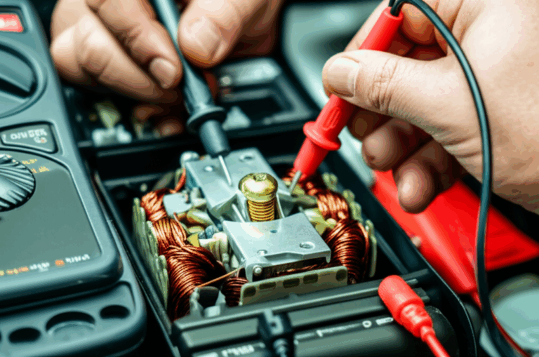
Quality control that saved me money and time
Inspection habits saved me from bad shipments and late-night fixes. These checks look simple. They catch big problems early.
- Measure thickness and flatness. A micrometer and a granite plate go a long way. If flatness drifts the stack won’t pack tight. You lose stacking factor and you fight assembly.
- Check burr height and direction. I run my finger along the edge and I measure with a feeler gauge. I decide stack orientation based on that. For tight air gaps burrs can wreck the plan.
- Test coating integrity. I use a simple dielectric test between sheets. I look for arcing spots or rubbed-off areas. I also soak a sample in my varnish and bake it. If the coating chalks I don’t approve it.
- Weigh the stack and measure height. That gives a direct stacking factor. No assumptions. I use that number in my magnetic calculations and in my thermal model.
- Run a core loss test on a ring or sample stack. I don’t always have a full Epstein setup. I still push a known flux at operating frequency through a test core and measure watts. Relative comparisons help me catch out-of-spec batches.
- For motors I run a back EMF test across slow speeds on a bare stator and rotor. The waveform shape tells me if slotting and tolerances line up. I also measure cogging torque before I wind. Early signals save rework.
Manufacturing trade-offs that change the outcome
I used to think tolerances were a single line on a print. Now I treat tolerances like a story. What you ask for changes the process. The process feeds back into cost and performance.
- Tight inside corner radii push you to wire EDM or better dies. That adds cost. It can add life to your motor performance when slot shape matters. I don’t tighten radii unless it moves the needle.
- Skewed stacks require special fixturing and sometimes special dies. I plan the skew angle around standard options. I design assembly steps that keep it simple.
- Interlock features reduce secondary operations. They can increase local loss if you place them in high flux areas. I move them to the yoke or away from teeth when possible.
- Welds are quick. They raise local loss and can warp. I weld into low flux areas and I clamp during weld to hold shape.
- Adhesive bonding gives great damping and uniform stacks. It needs clean parts and process control. I choose it when noise or loss goals demand it. I skip it in rugged low-cost units where the gains won’t show.
Each choice touches the others. I keep a living spreadsheet of what a change buys in performance and what it costs on the floor. That keeps me honest when I promise a spec to a customer.
Common mistakes I made and how I solved them
- I once spec’d a thin lamination for a slow, heavy-duty motor. The iron loss improved a little. The cost jumped. The machine ran no cooler because copper loss dominated. I moved back to thicker stock and used the budget on better winding fill and cooling.
- I ignored coating compatibility with my varnish. After the bake the coating turned powdery. Stacking factor dropped in the next batch because friction changed. I added a bake test in my incoming inspection and solved it.
- I let burrs face the air gap in a small high-speed motor. The gap closed unevenly and torque ripple shot up. We flipped the stack orientation and trimmed burrs at the source. Cogging dropped and noise fell.
- I trusted “nominal” flux numbers without worst-case current spikes. The rotor back saturated in a PM motor under a short pulse. Torque-per-amp went off a cliff. I thickened the rotor back and added a demag check to the test plan.
- I used laser-cut laminations for a high-efficiency prototype and believed the numbers. The final stamped version ran cooler at the same load. The HAZ from the laser had hidden loss. I now flag laser-cut data as provisional.
Cost versus performance: how I justify the spec
I’ve learned to quantify the value of better laminations. I take the incremental cost of a better grade or thinner sheet and translate it into watts saved at typical duty. Then I convert watts into energy and temperature rise.
- If my motor runs many hours per day energy savings add up. The better steel pays for itself over time.
- If I chase torque density the better steel lets me shrink stack height or reduce copper. That drops weight and material. It can save more than it costs.
- If I need low noise and smooth torque better laminations and better stacking reduce acoustic signature. That can open doors in markets that care about sound.
- If I face thermal limits the reduction in iron loss gives me margin. That margin can avoid a fan, a bigger heat sink, or a redesign.
I don’t upgrade blindly. I test at representative points. I build a small A/B comparison. I let data make the case.
A practical selection checklist you can reuse
When I start a new motor or transformer this is the checklist I run.
1) Define operating frequency and peak flux. Include worst-case current and speed.
2) Choose GO vs NGO steel based on flux direction. Motors want NGO. Power transformers often want GO.
3) Select lamination thickness based on frequency and budget. 0.5 mm for low frequency. 0.35 mm or thinner for higher frequency or high efficiency.
4) Pick a coating that matches bonding and bake process. Confirm thermal class.
5) Set realistic stacking factor. Confirm with a sample stack before final modeling.
6) Design slots and teeth with winding and insulation in mind. Leave space for end turns and liners.
7) Decide on skew and interlock early. Check the impact on tooling.
8) Set tolerances you can hold. Align with your stamping or cutting method.
9) Plan inspection: thickness, flatness, burr, coating, stacking factor, and sample core loss.
10) Validate with early builds. Measure back EMF, cogging, and temperature rise before full tooling.
If I’m focused on motors I start from stator and rotor requirements and loop back to material. If I’m focused on transformers I start from volt-per-turn and core area then pick a joint strategy.
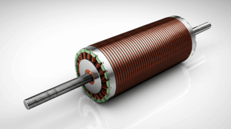
A quick note on component specifics. When I dig into complete motor assemblies I review the core stack, slot pattern, and row-to-row consistency. Resources that walk through complete assemblies of motor core laminations help me scope trade-offs across stators and rotors. If I’m diving deep into a single stator geometry the more focused look at a stator core lamination has been useful for slot and tooth considerations. When I’m troubleshooting magnet placement and mechanical strength in the rotor the detail in a rotor core lamination overview lines up with the realities I see on the bench. For broader material background and coating options the overview of electrical steel laminations sets a solid foundation for decision making.
Final thoughts
Laminations don’t look glamorous. They decide how your motor or transformer behaves under stress. The right material and a clean stack turn a decent design into a great product. The wrong choices leak heat and noise into everything you build.
I keep things simple now. Model with realistic stack factors. Choose steel for the job not for the brochure. Cut and stack with discipline. Test early. Inspect always.
Do that and your iron will carry you instead of fighting you.