Do DC Motors Use Stators? The Definitive Answer
If you design, source, or maintain electric motors you have probably run into the term stator. You see it everywhere in AC machines and BLDC data sheets. Then someone shows you a brushed DC motor with a commutator and says the windings are on the rotor. So… is there even a stator in a DC motor?
Short answer. Yes. Every DC motor has a stationary magnetic system that plays the stator’s role. The naming shifts by motor type which is what causes the confusion. Once you see how the stationary part creates the magnetic field the picture clears up fast.
Before we dive in let’s set up a quick roadmap.
In This Article
- What is a Stator? A Quick Definition
- Stators in Traditional (Brushed) DC Motors
- Stators in Brushless DC (BLDC) Motors
- Comparing Stator Function Across DC Motor Types
- Why the Confusion? Stator vs. Field System vs. Armature
- Material and Lamination Fundamentals for DC Motor Stators and Rotors
- Manufacturing and Assembly Options for Stator and Rotor Cores
- Which Application Is This For? Selection Guide
- Key Takeaways: Is a Stator Used in DC Motors?
- Frequently Asked Questions (FAQs)
- Sources and Standards
What is a Stator? A Quick Definition
A stator is the stationary part of an electric motor or generator. It provides a magnetic field that the rotor interacts with to produce torque. That field can come from permanent magnets or from windings energized as electromagnets. The rotor is the rotating part. The air gap sits between them. Magnetic flux crosses that air gap. Torque follows the Lorentz force law which says a current-carrying conductor in a magnetic field experiences a force.
Engineers also speak about armature windings and field windings. The armature carries the power that interacts with the magnetic field to produce torque. The field winding provides that magnetic field if magnets are not used. In AC motors the armature usually sits on the stator. In many brushed DC motors the armature sits on the rotor. That inversion drives most of the naming confusion.
Stators in Traditional (Brushed) DC Motors
You will not always hear the word stator around brushed DC motors. You will hear field system, field winding, yoke, and pole pieces. Those words point to the same stationary function a stator provides.
The “Field System”: The Brushed DC Motor’s Stator Equivalent
The field system is the stationary magnetic circuit. It bolts to the housing or yoke. It shapes the magnetic flux that crosses the air gap to meet the rotor or armature.
Two main versions exist.
- Permanent Magnet DC (PMDC) Motors
- Permanent magnets mount on the yoke. They create fixed North and South poles. No field current is needed.
- The magnets function as the stator’s source of magnetic field. There are no stator windings in this case.
- You still need a laminated path for flux in the frame or pole shoes. The aim is to minimize core losses and hold magnet shape and tolerances.
- PMDC motors shine in small DC motor applications like toys, fans, and automotive actuators. Low cost. Simple control with a DC power supply and a speed control circuit.
- Wound Field DC Motors: Series, Shunt, and Compound
- Coils wrap around pole pieces on the yoke. Those coils form electromagnets called field windings. They generate the main field.
- The windings are stationary. Engineers often call this assembly the stator or field system.
- Series wound DC motors deliver high starting torque. Shunt wound DC motors offer good speed regulation. Compound wound motors mix both features.
- Field current can be varied for control. That gives design freedom for torque and speed curves in traction and industrial drives.
In both PMDC and wound field designs the stationary magnetic field comes from the field system. It is the stator by function.
The Role of the Armature (Rotor) in Brushed DC Motors
The rotor carries the armature windings. Current enters through brushes and a commutator. The armature interacts with the stationary magnetic field. The commutator provides mechanical commutation so torque stays in a consistent direction. The armature generates back EMF proportional to speed. That back EMF affects current and thus speed control. Bearings support the shaft. End bells and the housing close the assembly.
Key pieces to remember
- Armature winding on the rotor
- Commutator and brushes handle switching
- Torque production depends on the interaction of armature current and stator field
- Interpoles and compensating windings correct commutation issues in large machines
- Proper air gap and pole shoe geometry influence performance and noise
Stators in Brushless DC (BLDC) Motors
BLDC motors bring the word stator back front and center. The stator contains the armature windings. The rotor carries permanent magnets. An electronic controller switches the stator currents. Hall effect sensors or back EMF detection provide rotor position feedback. That coordination creates a rotating magnetic field in the stator. The magnets on the rotor chase that rotating field. Torque follows.
Where the Stator Truly Shines: The BLDC Configuration
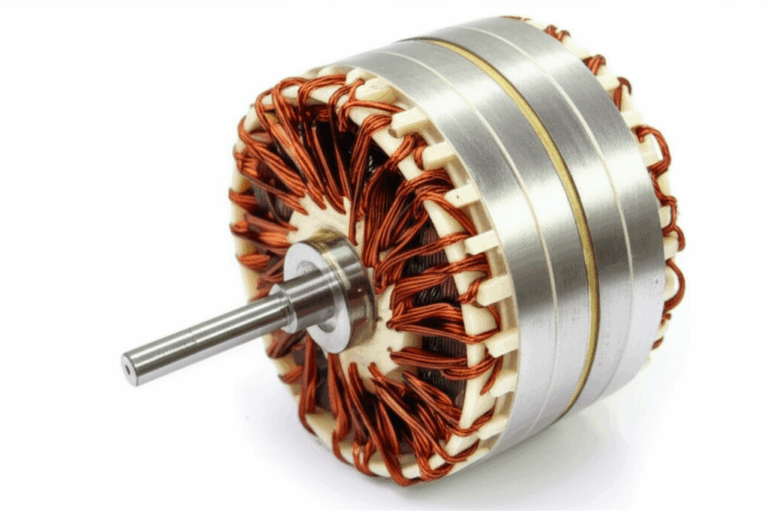
- The stator is a laminated steel core with slots. Copper coils sit in the slots as three-phase windings. The controller commutates electronically. The result is a smooth rotating magnetic field.
- Stator laminations reduce eddy currents and hysteresis loss. That keeps efficiency high. It lowers temperature rise and extends service life.
- The BLDC stator aligns with the AC motor stator concept. The armature windings are stationary which simplifies heat removal and insulation life.
- You can choose distributed windings or concentrated windings. You can choose slot-pole combinations to tune torque ripple and back EMF shape.
The Rotor in BLDC Motors: Permanent Magnets Take the Stage
- Rotor magnets can be surface-mounted or interior (IPM). IPM rotors allow saliency which enables field-weakening for higher speed ranges.
- Magnets set the peak flux density. Magnet selection affects back EMF constant and torque constant. You must manage demagnetization risk and temperature limits.
- Rotor balance, mechanical retention of magnets, and low-loss rotor sleeves matter for high speed.
Comparing Stator Function Across DC Motor Types
Let’s draw a clean line.
- Brushed DC Motors
- Stationary magnetic field comes from permanent magnets or field windings. That is the stator function even if people call it the field system.
- Armature windings live on the rotor. The commutator handles switching mechanically.
- Brushless DC Motors
- Stator contains armature windings. The controller switches them to create a rotating magnetic field.
- Rotor carries permanent magnets. No brushes. No commutator. Electronic commutation replaces them.
- Stepper Motors and Servo Motors
- Stepper motor stators carry multiple phase windings. The controller energizes phases in sequence. The rotor aligns step by step.
- Many servo motors use BLDC or AC synchronous designs. The stator carries the armature windings. An encoder provides position feedback.
Different names. Same physics of magnetic field generation and torque production.
Why the Confusion? Stator vs. Field System vs. Armature
Terminology tracks where the armature windings sit.
- In AC induction motors and synchronous motors the stator holds the power windings. Everyone calls it the stator. The rotor is either a squirrel cage or a magnet/salient pole assembly.
- In brushed DC motors the windings that carry armature current sit on the rotor. The stationary magnets or field coils are called the field system. Many textbooks reserve stator for AC machines which muddies the waters for newcomers.
- BLDC motors align with the AC approach. The armature sits on the stator. The stationary part is universally called the stator.
If you focus on function you avoid confusion. The stator is the stationary magnetic field creator. That function exists in every DC motor.
Material and Lamination Fundamentals for DC Motor Stators and Rotors
Now let’s get practical. The stationary magnetic field rides through steel. The details of that steel and how you build the core have a direct impact on torque, back EMF, losses, and noise. That is where laminations matter.
Why laminations exist
Alternating magnetic fields induce circulating currents inside conductive cores. We call them eddy currents. Think of them like little whirlpools in a river. They waste energy as heat. Thinner insulated laminations chop those whirlpools into tiny swirls. Losses drop. Hysteresis losses also matter. The material’s B-H curve shape and coercivity affect how much energy the core uses to flip magnetization each cycle.
Back to DC motors. Brushed DC motors see ripple in flux due to commutation and slotting. BLDC motors see time-varying fields as phases are switched. Induction due to slot harmonics and PWM adds to the picture. Laminations help in all of these cases.
Common lamination materials
- Non-oriented silicon steel (CRNGO)
- Good all-purpose choice for stator and rotor cores in many DC motors. It balances cost and performance. It handles multi-directional flux paths common in BLDC stators.
- Grain-oriented silicon steel (CRGO)
- Designed for transformers with uni-directional flux. It has very low loss along the rolling direction. It sees less use in rotating machines because flux rotates.
- High silicon grades and low-loss M-grades
- Higher resistivity. Lower eddy current loss. Often used in higher frequency or high efficiency designs.
- Cobalt alloys
- Very high saturation flux density. Useful for high power density and aerospace. They cost more.
- Soft magnetic composites (SMC)
- Powder iron with insulation around each particle. Useful for 3D flux paths. Often limited in core loss vs silicon steel at higher frequency.
You will see these materials specified as electrical steel laminations. You will see surface coatings for interlaminar insulation. Coating classes affect punchability, weldability, and stacking factor. You can explore options for electrical steel laminations that align with your frequency range and loss targets.
Lamination thickness and core loss
- Thinner laminations reduce eddy current loss. They raise cost and may reduce stacking factor. Typical thickness spans 0.2 to 0.65 mm for many machines. High-speed BLDC designs can push thinner.
- Hysteresis loss scales with frequency and material coercivity. Lower coercivity helps. Material grade selection matters.
- Surface coatings matter. They provide insulation between sheets. They also influence press lubrication and weld behavior. Pick coatings that fit your assembly process.
Magnetic circuit considerations in DC motors
- Flux density in the teeth and yoke
- Air gap length and uniformity
- Pole shoes shape and chamfer that control flux distribution
- Interpoles and compensating windings in large brushed machines for commutation stability
- Back iron thickness to prevent saturation
- Slot-Pole combinations in BLDC that set cogging torque and torque ripple
- Core losses in rotor stacks in BLDC if you use interior permanent magnets or flux barriers
Think of magnetic permeability like how easily a sponge soaks up water. A material with high permeability lets magnetic flux flow with less “resistance.” That reduces magnetizing current for wound field systems and keeps flux where you want it.
Stators and rotors as stacks
Real motors use stacks of punched or cut laminations. The stacks form the stator core and the rotor core. The quality of the stator core lamination and the quality of the rotor core lamination drive performance. Dimensional tolerances affect slot fill. Stacking factor affects axial length requirements. Burr height affects interlaminar shorting and core loss. Heat-affected zones from laser cutting can alter magnetic properties if not managed.
Manufacturing and Assembly Options for Stator and Rotor Cores
You have several paths from CAD to stacked cores. Each path carries tradeoffs for cost, tolerances, and performance.
Blanking and stamping
- High-volume go-to. Hard tools deliver speed and tight repeatability. Per part cost drops at scale. Upfront tooling cost is higher.
- Careful tool design keeps burrs low. Burr direction matters for stacking. Grain direction matters for materials that are sensitive to rolling direction.
- Tool coatings and lubrication extend life and improve edge quality.
Laser cutting and waterjet
- Ideal for prototypes and low-volume runs. Complex geometries are easy. No hard tooling cost. Per part cost runs higher.
- Laser cutting introduces a heat affected zone. That zone can raise local loss if you do not optimize parameters. Post processing can help.
- Waterjet avoids thermal effects. Edge quality and taper need attention.
Wire EDM
- Great edge quality with minimal burr. Slow. Often used for precision thin webs and special prototypes.
Bonding, welding, riveting, and interlocking
- Interlocking laminations snap together like LEGO bricks. They create rigid stacks without welding. They avoid thermal damage. They require features in the lamination design.
- Bonded stacks use adhesive coatings or resin to bond layers. Very good for noise control and loss reduction. Process control is critical.
- TIG or laser welding sets end joints or outer seams. Manage heat to protect magnetic properties. Welding can raise local loss if overdone.
- Riveting and cleating provide mechanical fastening. They add local stress and can complicate assembly.
Coatings and insulation
- Coating class influences punchability. It influences bonding and weld compatibility. It sets interlaminar resistance which targets eddy current suppression.
- Pick coating types that fit your assembly route and operating temperature.
Slot insulation and copper choices
- Slot liners protect the winding from core edges. Choose materials rated for temperature class.
- Copper wire grade and insulation class influence current density and thermal life. Litz wire can help at higher frequencies and with PWM harmonics.
- Winding method matters. Form wound vs. random wound. Concentrated vs. distributed. Each affects fill factor and thermal path.
Tolerances and metrology
- Slot width tolerance affects slot fill and insertion force. It also affects tooth tip geometry which can alter flux density.
- Rotor OD and stator ID tolerances set the air gap. That gap drives torque constant and efficiency. You need consistent bearings and end bells to hold the gap in service.
- Lamination burr height control prevents interlaminar shorts. Keep it low and consistent.
For BLDC programs you often evaluate a dedicated bldc stator core for each pole-slot variant. That lets you dial in torque ripple, acoustic noise, and efficiency with fewer mechanical compromises.
Which Application Is This For? Selection Guide
Let’s match motor type and use case to stator function, material choice, and manufacturing approach. This guide helps you move from concept to a manufacturable core.
Brushed DC Motor (PMDC)
- Stationary part
- Permanent magnets on a steel yoke. No stator windings.
- Pros
- Simple control and low cost. No field losses.
- Consider if you need
- Small DC motor components in toys, fans, small appliances, and automotive actuators.
- Material and process
- Yoke and pole shoes in low-loss steel if you expect ripple. Magnet grade sets torque constant. Press-brake formed housings are common. Use stamping for any pole shoes.
- Watch for
- Demagnetization risk at high temperature and high armature current. Brush wear. Balance between torque ripple and acoustic noise.
Brushed DC Motor (Wound Field: Series, Shunt, Compound)
- Stationary part
- Field windings on laminated pole pieces. This is your stator by function.
- Pros
- Adjustable field for speed control. High starting torque for series motors. Strong industrial heritage.
- Consider if you need
- High power industrial drives. Traction motors in legacy platforms. Robust torque control via field current.
- Material and process
- Non-oriented silicon steel for pole pieces with proper lamination thickness. Stamping makes sense at volume. Bonding or interlocking keeps losses low. Good for repair and maintenance because field coils are accessible.
- Watch for
- Brush and commutator maintenance. Spark suppression. Thermal rise with high current. Interpoles or compensating windings may be needed for clean commutation.
BLDC Motor
- Stationary part
- Laminated stator with three-phase armature windings. This is the stator in name and function.
- Pros
- High efficiency. No brushes. Wide speed range with electronic control. Good power density.
- Consider if you need
- Drones, robotics, EV traction auxiliaries, medical devices, computer fans, servo applications.
- Material and process
- Low-loss non-oriented silicon steel at appropriate thickness. Stator slot design to manage cogging torque. High fill factor windings. Consider skew, fractional-slot combinations, or shaping of the magnet and tooth tips to reduce torque ripple.
- Watch for
- Controller cost and complexity. EMI management. Rotor containment for high speed. Thermal path from copper to housing.
Stepper Motor
- Stationary part
- Laminated stator with many poles. Phases switch in sequence.
- Pros
- Precise positioning without feedback at short stroke or low speed.
- Consider if you need
- 3D printers, CNC indexing, cameras, and valve actuation.
- Material and process
- Laminations with tooth shaping for holding torque. Assembly methods that keep stacks rigid and quiet.
- Watch for
- Resonance and vibration. Efficiency is lower than BLDC at high speed. Heat at hold torque.
Universal Motors
- AC or DC operation with a series field winding and a commutated armature on the rotor.
- Pros
- Very high speed. High power density. Simple control on line power.
- Watch for
- Brush wear. Noise. Use in appliances and power tools where duty cycles are short.
Your Options Explained: Material Considerations vs. Manufacturing Processes
Here is a clean way to frame your decisions.
Material considerations
- Silicon steels (M grades and CRNGO)
- Ideal for general-purpose DC motor components. Good balance of cost and performance. Works for BLDC stators and brushed field poles. Look at grade data sheets for loss vs. frequency.
- Cobalt alloys
- High saturation for maximum torque density. Use when space is tight and budgets allow. Great for aerospace and high power density equipment.
- Permanent magnets
- PMDC and BLDC depend on magnet grade. NdFeB offers strong flux. SmCo tolerates heat better. Ferrite lowers cost for less torque density.
- Laminated steel core thickness
- Thinner reduces core loss at higher electrical frequencies. It increases part count and handling complexity. You must balance loss and cost.
- Coatings
- Choose based on assembly process and operating temperature. They set interlaminar resistance and affect weldability.
You can also review broad material families under electrical steel laminations to see typical grades and coatings used in stators and rotors.
Manufacturing and assembly processes
- Stamping
- Best for high-volume production. Low cost at scale.
- Laser cutting
- Best for prototypes and low volume. Watch for heat affected zones. Great for quick iteration when you are exploring slot-pole variants and magnet arcs.
- Bonding and interlocking
- Great for low noise and low loss. Interlocking avoids weld heat. Bonding improves damping and acoustic behavior.
- Welding and riveting
- Useful for mechanical integrity. Apply carefully to protect magnetic properties.
- Winding and insertion
- Automated insertion speeds production for distributed windings. Needle winding suits concentrated windings. Fill factor and slot liner selection set current density limits.
If you are targeting a BLDC program with fractional slot concentrated windings a proven bldc stator core baseline shortens development. You still own optimization of slot geometry, skew, and magnet shape to hit torque ripple and acoustic targets.
What’s Really Going On? The Engineering Fundamentals
Let’s connect the physics to what you see on the bench.
- Magnetic field generation in DC motors
- Field poles produce flux. The flux crosses the air gap and reaches the armature. The armature carries current. The Lorentz force law drives torque.
- Back EMF in DC motors
- A moving conductor in a magnetic field generates voltage. That is Faraday’s law of induction. In a motor that voltage is called back EMF. It rises with speed. It limits current naturally at higher speed. It also provides a way to estimate speed in sensorless BLDC.
- Direction and control
- Reverse polarity to reverse DC motor rotation. BLDC reverses by swapping phase sequence in the controller.
- Magnetic materials
- Laminated steel core raises efficiency by reducing eddy currents and hysteresis losses. Laminations help both stators and rotors. Even rotors with magnets benefit from laminated back iron. Interior PM rotors often use segmented laminations with flux barriers for saliency.
- Losses and heat
- Core losses include eddy currents and hysteresis. Copper losses scale with current squared. Mechanical losses come from bearings and windage. Brush contact adds loss in brushed motors. Temperature rise follows the loss balance and cooling method. Manage it for service life.
Imagine the magnetic circuit like roads in a city. The stator yoke is a ring road. Teeth are the on-ramps. Flux traffic wants the shortest path through the air gap to the rotor. Laminations keep the roads cool and smooth. Good design moves flux without bottlenecks.
Matching the Right Solution to Your Application
No single stator construction fits every DC motor. Use these quick patterns.
- High torque at stall or low speed
- Series wound brushed DC or BLDC with many poles. Watch copper loss and heat. Use thicker copper and robust slot liners. Ensure mechanical commutation or electronic commutation remains stable.
- High efficiency across a wide speed range
- BLDC with well-designed stator slots and magnets. Use lower loss laminations and thin sheets. Tune the controller for field weakening if needed. Optimize for low core losses at your PWM frequency.
- Low cost and simple control
- PMDC with ferrite magnets for lower torque density or NdFeB for more torque. Maintain clean brush commutation and adequate cooling.
- Precise positioning
- Stepper motor with a stator tuned for holding torque and low resonance. Or BLDC servo with encoder and high bandwidth control.
Procurement and manufacturing strategy also matters.
- Prototype and early pilot builds
- Laser cut laminations or waterjet. Accept slightly higher loss for speed of iteration. Focus on slot fill and thermal path. Validate torque and back EMF constants.
- Pre-production
- Shift to stamped laminations or hybrid flows. Introduce bonding or interlocking. Validate acoustic targets and temperature rise.
- Mass production
- Fully tooled stamping with high repeatability. Optimize coating selection and line balancing. Lock in stacking, skew, and QA checks. Audit air gap variation across builds.
For complete motor programs you will likely source both stator and rotor stacks. Review motor core laminations to align stack strategies with your cost and performance envelope.
Key Takeaways: Is a Stator Used in DC Motors?
- Yes. Every DC motor has a stationary magnetic component that fills the stator role. The naming changes by motor type.
- Brushed DC motors
- The stationary part is the field system. It uses permanent magnets or field windings. That is the stator by function.
- Brushless DC motors
- The stator is explicit. It houses the armature windings. The controller energizes them to create a rotating magnetic field. The rotor carries magnets.
- Laminations matter
- Laminated steel cores slash eddy current loss. They control hysteresis loss. They set your efficiency and temperature rise.
- Manufacturing choices drive outcomes
- Stamping rules at volume. Laser cutting powers prototyping. Bonding and interlocking reduce noise and loss. Welding and riveting provide mechanical integrity with care.
- Design for your use case
- Choose materials, lamination thickness, and assembly to match your torque, speed, efficiency, and budget targets.
Frequently Asked Questions (FAQs)
Q: What’s the main difference between a brushed and brushless DC motor’s stationary part?
A: In a brushed DC motor the stationary part is the field system. It uses permanent magnets or field windings to create a fixed magnetic field. In a BLDC motor the stator holds the armature windings. The controller switches them to create a rotating magnetic field.
Q: Can a DC motor operate without a stator?
A: No. A DC motor needs a stationary magnetic field source to interact with the rotor. You can call it the stator or the field system. The function must exist.
Q: Are the windings in a DC motor always on the stator?
A: No. In brushed DC motors the armature windings sit on the rotor. In BLDC motors the armature windings sit on the stator. Field windings, if present in brushed motors, sit on the stationary frame.
Q: What material is a stator typically made from?
A: Laminated electrical steel forms the stator core. The laminations are thin sheets with insulation between layers. Copper wire forms the windings in wound stators. Permanent magnets may sit on the stationary frame in PMDC designs.
Q: How does lamination thickness affect motor efficiency?
A: Thinner laminations reduce eddy current loss which improves efficiency and lowers temperature rise. They increase manufacturing complexity and cost. You choose thickness to match frequency content and cost targets.
Q: What is the yoke in a DC motor?
A: The yoke is the outer frame that completes the magnetic circuit. It supports field poles and provides a path for flux. It is part of the stationary magnetic circuit.
Q: What are interpoles and compensating windings?
A: Interpoles are small auxiliary poles between the main poles in large brushed machines. They help commutation by inducing a voltage that counters armature reaction. Compensating windings sit in slots in the pole faces. They also counter armature reaction under heavy load.
Q: Does the BLDC rotor need laminations?
A: Even with permanent magnets the rotor back iron often uses laminations to reduce loss from slot harmonics and PWM fields. Interior PM rotors use laminated stacks with flux barriers for saliency and strength.
Q: How do I reduce cogging torque in BLDC motors?
A: Use fractional slot windings. Skew the stator or magnets. Optimize tooth tips and magnet arc. Adjust slot opening. These techniques smooth the torque ripple.
Q: Which standards should I consider?
A: IEC 60034 covers rotating electrical machines. Many materials follow recognized specifications from ISO and ASTM. Performance validation often references IEEE papers and test practices.
Problem – Explain – Guide – Empower: Your Practical Next Steps
Problem
- You must decide if a DC motor includes a stator and what that means for your design and sourcing. You also need to pick materials and processes for the stationary magnetic circuit. Your choices hit efficiency, torque, cost, and lead time.
Explain
- Every DC motor uses a stationary magnetic field. That is the stator’s function. In brushed DC motors we call it the field system. In BLDC the stator holds the armature windings. Laminated electrical steel cores reduce core losses. Permanent magnets set flux where used. Commutation is mechanical in brushed motors and electronic in BLDC.
Guide
- Choose motor type first. Brushed for simplicity and high starting torque. BLDC for efficiency and low maintenance. Then pick materials and lamination thickness to match frequency content and performance. Decide on stamping for volume or laser cutting for prototypes. Select bonding or interlocking for lower losses and noise. Validate torque, back EMF, temperature rise, and acoustic noise with representative prototypes. Confirm tolerances that hold a consistent air gap.
Empower
- Define your motor’s duty cycle, peak torque, continuous torque, speed range, and ambient temperature. Lock the slot-pole combination and magnet approach. Select lamination grade and thickness with supplier input. Review sample stacks or request a design for manufacturability check. If you plan high volume start conversations about tooling and QA gates now. If you are still iterating keep to flexible processes. You can explore stator core lamination and matching rotor core lamination options to align engineering targets with a realistic supply plan.
Sources and Standards
- IEC 60034 Rotating electrical machines
- IEEE Transactions on Energy Conversion and IEEE Transactions on Industry Applications for peer-reviewed motor design and materials research
- Material data sheets from established electrical steel producers for loss curves, B-H curves, and coating specifications
Final note. Names can mislead. Physics will not. Whether you call it a stator or a field system the stationary magnetic circuit makes or breaks your DC motor. Choose your materials and processes with care. Validate early. Then scale with confidence.