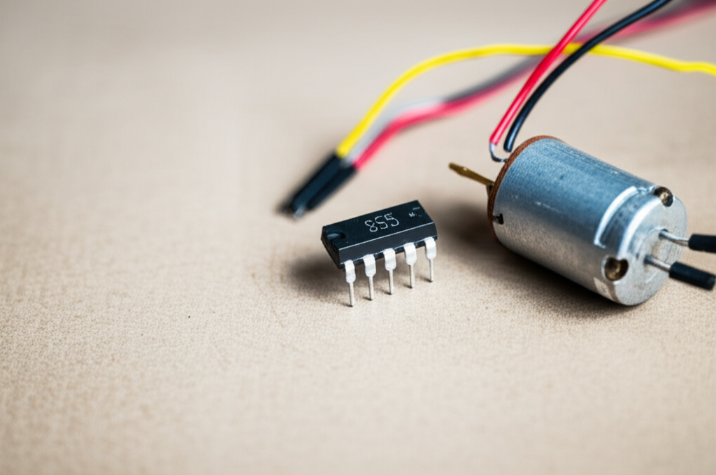
Can I Use a 555 Timer on a 3V Motor? (Yes, Here’s How I Make It Work)
Table of contents
- Introduction: The short answer and what matters most
- Understanding 555 timer compatibility with 3V systems
- Output current limits and why direct drive fails
- Minimum operating voltage for different 555 variants
- Essential external driver circuits for 3V motors
- Option 1: Single transistor or MOSFET driver
- Option 2: Dedicated H-bridge motor driver ICs
- Powering and grounding a 3V motor PWM circuit
- Designing a 555-based 3V motor speed controller
- My go-to schematic and how I wire it
- Component selection guide
- Choosing PWM frequency and duty cycle
- Example values that work on the bench
- Common issues and how I troubleshoot them
- Alternatives to a 555 for 3V motor control
- Practical tips, small mistakes, and lessons learned
- Conclusion: Use the 555 as a PWM brain, not a bicep
Introduction: The short answer and what matters most
I’ll give you the straight answer first. You can absolutely use a 555 timer to control a 3V DC motor. I do it often when I want a quick and cheap PWM speed controller. The trick is simple. Don’t drive the motor directly from the 555. Use the 555 as a PWM generator and pass the heavy lifting to an external switching stage like a logic-level MOSFET or a motor driver IC.
When I first tried this years ago on a tiny toy motor I wired the motor straight to the 555 output because the datasheet said “high output current.” The chip got hot. The motor twitched then stalled. That was my wake-up call. A 3V motor pulls way more current than a 555 can source or sink, especially at startup and stall. You need a driver.
Here’s the plan. I’ll walk you through what works for me at 3V, which 555 variant to pick, how to wire a MOSFET driver with a flyback diode, the PWM ranges that feel smooth, and the common mistakes that waste batteries or blow parts. I’ll also share when I switch to a dedicated H-bridge like the DRV8833 for bidirectional control.
Understanding 555 timer compatibility with 3V systems
Output current limits and why direct drive fails
A 555 timer looks tough on paper. Many bipolar NE555 datasheets show high output drive capability. On the bench the story changes. A small 3V DC motor can draw 100 mA to 500 mA under load and several times that at stall. Even when the motor spins freely the current spikes at turn-on and whenever the load changes. The 555 was never meant to deliver that kind of current to an inductive load.
I learned this the hard way. The 555 gets warm, the motor sags, the supply droops, and the PWM duty cycle goes weird. You also risk inductive kickback from the motor winding going straight into the 555 output stage. That’s a fast track to latch-up or failure. Bottom line. Use the 555 to create a clean PWM signal. Let a transistor, MOSFET, or motor driver IC handle current.
Two other gotchas show up when you push a 555 hard at low voltage:
- The output does not swing perfectly to the rails on many bipolar versions. At 3V every tenth of a volt matters.
- The output resistance and voltage drop grow with current. That wastes precious battery power and robs the motor of torque.
Minimum operating voltage for different 555 variants
Not all 555s behave the same at 3V. This matters more than people think.
- Standard NE555 (bipolar): Typical VCC range is 4.5 V to 16 V. I don’t use an NE555 directly on a 3V supply.
- CMOS 555 variants like TLC555, LMC555, and similar: These can operate down to around 2 V to 3 V depending on the exact part. They draw less quiescent current and the outputs swing closer to the rails. That helps a lot when you need to drive a MOSFET gate at 3 V.
I keep a small bag of CMOS 555s just for low-voltage projects. When the battery is only two alkaline cells or a single lithium cell, CMOS wins by a mile.
Essential external driver circuits for 3V motors
Option 1: Single transistor or MOSFET driver
This is my default for simple speed control in one direction.
- N-channel logic-level MOSFET
- Why I prefer it: Low voltage drop, higher efficiency, and better at handling stall current. With the right device the motor sees almost the full 3 V.
- What to look for: A logic-level MOSFET with a low Rds(on) specified at Vgs = 2.5 V or even 1.8 V. That spec matters. If the datasheet only shows low Rds(on) at 10 V you’ll get disappointing results at 3 V.
- Examples that have worked for me: AO3400, Si2302, IRLML6344, PMV30UN. Many others can work if they have a solid Rds(on) at low gate voltage.
- Bipolar Junction Transistor (BJT)
- When I use one: For very small motors with low current, or if I only have BJTs on hand.
- Trade-offs: A BJT in saturation drops 0.2 V to 0.7 V depending on current. On a 3 V supply that hurts torque. You must size a base resistor and supply enough base current. BJTs also waste more power as heat at higher currents.
- Flyback diode
- Non-negotiable. A motor is an inductor. Every time you switch it off the winding spits out a voltage spike. The diode clamps that spike and protects your MOSFET or BJT.
- What I reach for: A Schottky like SS14 or 1N5819 for small 3 V motors. If you only have 1N400x it works, though it’s slower. Size the diode for at least the stall current and give it a comfortable margin.
- Where it goes: Across the motor terminals, cathode to supply plus, anode to the transistor side. Keep the leads short.
Wiring in a sentence: 555 output goes through a small gate resistor to the MOSFET gate, motor connects from +3 V to MOSFET drain, MOSFET source to ground, and a flyback diode across the motor.
Option 2: Dedicated H-bridge motor driver ICs
If you want forward and reverse or you expect higher currents, an H-bridge driver saves time and headaches. The DRV8833 and TB6612FNG both handle 3 V motors well. They accept PWM and direction inputs, they protect against shoot-through, and they drop less voltage than old bipolar drivers.
A quick note on the classics. L293D and L298N get used a lot in tutorials, yet they are bipolar devices with significant voltage drop across the outputs. At 3 V that drop eats most of your headroom. I avoid them for low-voltage builds.
How I pair a 555 with an H-bridge:
- I let the 555 generate PWM.
- I send that PWM to the driver’s PWM input or EN pin.
- I use simple switches or a microcontroller to toggle direction pins if I need reverse.
Powering and grounding a 3V motor PWM circuit
Low-voltage motor control lives and dies by good power wiring. I learned to overdo the basics because 3 V systems have no room for sloppy drops.
- Power source
- Two alkaline AAs or AAAs work well. They sag under load so use fresh cells for testing.
- A single Li-ion or LiPo cell gives more torque but it sits at 4.2 V when full. You can either run the motor from the raw cell and regulate the 555 down or pick parts that tolerate the higher voltage.
- Decoupling
- Put a 100 nF ceramic close to the 555 VCC pin and a 10 µF to 47 µF electrolytic nearby.
- Add a bulk capacitor across the motor supply rails. I use 100 µF to 470 µF for little motors. This helps with battery sag and reduces audible chatter.
- Grounding
- Star the grounds if you can. The motor return current should not share long thin ground traces with the 555. I keep the 555 ground and timing network off the noisy motor return path.
Designing a 555-based 3V motor speed controller
My go-to schematic and how I wire it
Here’s the mental picture I use when I build the circuit on a breadboard or perfboard.
- 555 in astable mode to generate PWM. I use the “diode around the pot” trick so I can adjust charge and discharge times separately. That widens the duty cycle range.
- 555 pinout basics
- Pin 1 to ground, Pin 8 to +3 V.
- Pin 4 (RESET) tied to VCC for normal operation.
- Pin 5 (CONTROL) decoupled with a 10 nF capacitor to ground for noise immunity.
- Pins 2 and 6 tied together for astable mode.
- R1 from VCC to discharge pin (Pin 7), R2 and a diode network between Pin 7 and Pins 2/6, timing capacitor C from Pins 2/6 to ground.
- Output on Pin 3 drives the gate of the MOSFET through a small resistor (47 to 220 ohms).
- MOSFET low-side switch with a pull-down on the gate (100 k to ground) so the motor stays off during power-up.
- Flyback diode across the motor.
- Potentiometer in the timing network to adjust duty cycle.
If you prefer simplicity you can skip the diode around the pot. You’ll still get PWM but the duty cycle range gets narrower and you’ll see a minimum around 10% to 15% and a maximum around 85% to 90% depending on values.
Component selection guide
- 555 timer
- Pick a CMOS variant like TLC555 or LMC555. These run at 3 V and present a friendlier output for MOSFET gates at low voltage.
- External driver
- Logic-level N-channel MOSFET with low Rds(on) at Vgs = 2.5 V. For small table-top builds AO3400 and Si2302 do great work. For larger currents pick a device in a package that can shed heat.
- If you must use a BJT use a 2N2222 or similar and add a base resistor. Size it so base current is at least one tenth of collector current for decent saturation. Expect more heat and less speed at the same supply voltage.
- Flyback diode
- Use a Schottky like SS14 or 1N5819 for fast recovery and lower drop. Rate it for at least the stall current.
- Timing resistors and capacitors
- Pick values that place PWM frequency in the low kHz range. I aim for 1 kHz to 20 kHz.
- At 1 kHz you may hear the motor whine a bit. At 16 kHz and above the whine usually moves out of hearing range for most adults.
- Potentiometer
- 10 k to 100 k works well for the duty control. I like 50 k with a small series resistor to set a floor and ceiling for duty cycle so I don’t hit 0% or 100%.
- Gate resistor and pull-down
- 100 ohms in series with the MOSFET gate dampens ringing. 100 k to ground as a pull-down keeps the MOSFET off if the 555 output floats during startup.
Choosing PWM frequency and duty cycle
A few rules of thumb from my bench time:
- Frequency: 1 kHz to 4 kHz = easy and efficient. 8 kHz to 20 kHz = quieter. Above 20 kHz = safe for audible noise but switching losses in the MOSFET rise slightly.
- Duty cycle: Motors need some minimum duty before they overcome static friction. Many small 3 V motors start around 10% to 20% duty with no load. Under load they may need 30% or more to kick over. I design for a 5% to 95% duty range and I’m happy if I get 10% to 90%.
If you use the standard 555 astable without the diode hack the classic equations apply:
- Frequency f ≈ 1.44 / ((R1 + 2R2) × C)
- Duty cycle ≈ (R1 + R2) / (R1 + 2R2)
With a diode across part of R2 you break the symmetry. One path charges through one resistance. The other path discharges through another. That lets you slide duty without moving the frequency as much.
Example values that work on the bench
Here’s a set I return to when I build a small 3 V controller for a toy motor.
- C = 10 nF
- R1 = 1 k
- R2 = 100 k potentiometer with a 4.7 k series resistor
- A diode (1N4148 or similar) in parallel with part of R2 to separate charge and discharge paths
- MOSFET: AO3400
- Flyback: SS14
- Gate resistor: 100 ohms
- Gate pull-down: 100 k
- Bulk cap across supply: 220 µF electrolytic plus 100 nF ceramic
That set lands me near 1.5 kHz to 3 kHz. The motor speed adjusts smoothly, and I don’t hear much whine. If I need near-silent operation I swap C to 4.7 nF to push the frequency up around 8 kHz to 12 kHz.
Common issues and how I troubleshoot them
I’ve built this circuit enough times to know where it goes sideways. Here’s my short list.
- Motor not spinning or barely twitching
- Check the MOSFET orientation. Source to ground, drain to motor, gate to 555 output.
- Verify the motor’s stall current. Many “3 V” motors stall above 1 A. That can exceed your MOSFET or battery.
- If you used a BJT check the base resistor. Too large and you starve the base. Too small and you stress the 555.
- Make sure the flyback diode is across the motor with correct polarity. Backwards diodes cause headaches.
- 555 timer overheating
- This almost always means the motor current sneaks through the 555 somehow. Recheck your wiring. The 555 should only drive the MOSFET gate.
- Look for a short from output pin to VCC or ground through a low resistance path.
- Unstable operation or random resets
- The motor noise might be blasting the supply. Add more bulk capacitance near the motor. Improve the ground layout. Keep the timing network leads short.
- Add a 10 nF cap on the 555 CONTROL pin. Tie RESET to VCC solidly.
- Some breadboards have loose contacts that wreak havoc at kHz PWM. Re-seat or move the build.
- No speed control or odd duty range
- If the PWM frequency is too low you’ll see jerky motion. Raise frequency by lowering C or lowering R.
- If the duty range is narrow add the diode across the timing resistor to separate charge and discharge paths.
- Check the pot wiring. Wiper should go to the timing node with the two ends to the resistive path.
Alternatives to a 555 for 3V motor control
I love the 555 for quick PWM but it’s not the only game in town.
- Microcontrollers like Arduino, ATtiny, or ESP32
- They give you precise PWM, easy ramp profiles, and soft-start. You can read sensors, manage acceleration, and change direction with logic. At 3 V many MCUs run happily. You still need a MOSFET or driver to switch the motor current.
- Dedicated PWM generator ICs
- Some chips generate clean PWM without an MCU. These shine if you need stability over temperature or very specific duty ranges. They also offload the gate drive to external stages just like a 555.
- Motor driver ICs
- H-bridge drivers such as DRV8833 or TB6612FNG simplify wiring, support bidirectional control, and add current limiting and thermal protection. On small robots or toy mods I pick these when I want forward and reverse without fuss.
Practical tips, small mistakes, and lessons learned
Let me share a few lessons from real builds. These are the little things that save time.
- Don’t rely on gate threshold voltage
- The MOSFET’s Vgs(th) is the point where it barely starts to conduct. That number does not mean it’s fully on. Look for the Rds(on) at your actual gate voltage. At 3 V this single check prevents the “motor runs but weak” complaint.
- Respect stall current
- Measure it if you can. If the motor binds or the load jumps the current spikes. Size your MOSFET and diode for stall and then some. I had a gearmotor that stalled near 1.2 A. My tiny SOT-23 MOSFET lived on the edge until I swapped it for a beefier package.
- Heatsinking at 3 V
- People assume heat is a 12 V or 24 V problem. It’s not. Current causes heat in the silicon no matter the voltage. A MOSFET with low Rds(on) saves the day. If the package is small spread copper on the PCB or mount it where it can shed heat into air.
- Battery sag is real
- Two AAs look fine on a multimeter with no load. Under load they sag. Your 3 V turns into 2.4 V and the motor slows down. Add bulk capacitance and choose cells with decent internal resistance. Rechargeables like NiMH often sag less under short bursts.
- Use a scope if you have one
- Watching the gate waveform answers so many questions. You see ringing, slow edges, and supply dips. If you don’t have a scope, a multimeter on DC and AC ranges plus your ears do more than you think. Audible whine tells you if your PWM is in the audible band.
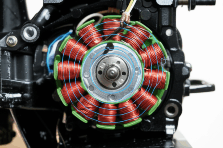
A quick detour into motor construction and noise
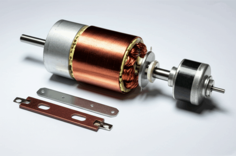
When you push a small DC motor at low voltage, efficiency and noise rise to the surface. The quality of the motor’s magnetic circuit shapes torque ripple and buzz. If you’ve ever torn down a motor you’ve seen the stack of thin metal sheets inside. Those sheets are laminations. They reduce eddy current losses and improve performance at higher speeds and PWM frequencies.
If you’re curious about what sits inside many motors and transformers these resources give a sense of the materials and shapes:
- You can see how manufacturers build and stack stator core lamination packs for compact motors.
- The rotating side uses matching steel stacks known as rotor core lamination.
- For a broader overview of different motor geometries and materials check out motor core laminations.
- If you want the material science angle, these are essentially precision-cut electrical steel laminations that tame eddy currents.
Why does this matter to a 3 V PWM build? Because PWM sends sharp edges into the windings. Better lamination and magnetic design reduce iron loss and heat at those frequencies. You get smoother speed control and less audible chatter.
Real build walkthroughs: what I actually did
Two quick examples from my bench.
- Tiny desk fan at 3 V
- Goal: Quiet speed control with a coin-cell sized brushed motor.
- Build: TLC555 for PWM, AO3400 MOSFET low-side, SS14 diode, 10 nF timing cap, 50 k pot, 220 µF bulk cap.
- Frequency: 12 kHz to push the whine out of earshot.
- Result: Smooth control from barely turning to full blast. The MOSFET stayed cool. Battery life improved compared to a series resistor because PWM wastes less power.
- Mini-robot drive
- Goal: Two motors forward and reverse with speed control on a 1S LiPo.
- Build: DRV8833 H-bridge with PWM from a TLC555 at first, then I swapped the PWM to a small MCU for independent channel control. 555 drove early tests just fine.
- Frequency: 2 kHz for the DRV8833. I bumped it to 10 kHz later to reduce audible noise in a quiet room.
- Result: Clean starts at mid duty cycle, strong torque, and less fuss about ground noise because the driver manages current paths.
Frequently asked questions I hear all the time
- Can a 555 directly drive a 3 V motor
- Not safely in my experience. Even if it twitches, the long-term reliability and performance suffer. Use an external switch.
- Is a BJT good enough
- For very small motors, yes. For anything with measurable torque, a logic-level MOSFET at 2.5 V or 3.3 V gate drive beats a BJT on drop and heat.
- What PWM frequency should I start with
- Start at 2 kHz. If you hear the motor whine and it bothers you, go up to 8 kHz to 16 kHz. Watch MOSFET temperature at higher frequencies.
- Why does the motor buzz at certain speeds
- You’re hitting mechanical resonances or your frequency sits squarely in the audible band. Change frequency or add a bit of bulk capacitance to damp supply ripple.
Quick wiring checklist so you don’t chase ghosts
- CMOS 555 powered at 3 V, RESET tied high, CONTROL pinned to ground through 10 nF.
- Astable network with a pot and diode gives wide duty range.
- 100 nF decoupling at the 555 VCC. 100 µF to 470 µF across the motor supply.
- Logic-level N-MOSFET with low Rds(on) at Vgs = 2.5 V. Gate series resistor 100 ohms. Gate pull-down 100 k.
- Flyback diode across the motor, short leads, correct polarity.
- Ground layout that keeps motor current out of the timing network.
- Battery that can deliver the current. Fresh cells or a capable Li-ion.
- Measure stall current. Size MOSFET and diode for it.
Microcontroller vs 555: when I switch tools
I still reach for the 555 when I want a one-knob speed control for a small 3 V motor. If I need:
- Bidirectional control with braking
- Acceleration ramps and soft-start
- Multiple channels with synchronized PWM
- Telemetry or closed-loop control with a tachometer
I go straight to a microcontroller and a proper driver IC. The code takes a bit more time. The result behaves better under changing loads, and I can tune it without swapping resistors and capacitors.
Safety and reliability notes I stick to
- Keep your hands off live wiring while testing. Even at 3 V the motor can pinch or fling small parts.
- Add a fuse or polyfuse on the battery if you expect high stall current. It’s cheap insurance.
- If the MOSFET runs warm in free air it will cook inside a sealed box. Ventilation matters. A small copper plane on a PCB does wonders.
- Label your breadboard power rails. I’ve reversed polarity more than once when I rushed.
Conclusion: Use the 555 as a PWM brain, not a bicep
Here’s the bottom line from my workbench. A 555 timer can control a 3 V DC motor very well. It should not and does not need to drive the motor directly. Let the 555 generate clean PWM. Hand the current to a logic-level MOSFET or a dedicated H-bridge. Pick a CMOS 555 for low-voltage operation. Size the MOSFET and flyback diode for stall current. Keep your power wiring tight and your grounds clean. Start around 2 kHz to 10 kHz for smooth speed control.
Do that and your 3 V motor will spin like a champ. You’ll get better efficiency, less heat, and longer battery life. Most of all you’ll avoid the common traps that frustrate beginners. I learned those lessons by burning a few parts and listening to buzzing motors in quiet rooms. You don’t have to.
Build it. Tweak the duty range. Nudge the frequency. Once you see the motor respond to your knob the way you expect, you’ll understand why the 555 still earns a place in my toolkit.
Happy building.