Can a Faulty Stator Damage Your Rectifier? An Engineer’s Guide to Root Causes, Testing, and Better Lamination Choices
Every design engineer has seen this movie. The battery keeps dying. Lights dim at idle. You swap a rectifier-regulator, and it fails again. The question bubbles up fast. Can a bad stator damage the rectifier? Yes. A failing stator can absolutely stress and ultimately destroy a rectifier-regulator. The two parts live in a tight feedback loop. When one drifts out of spec, the other picks up the slack until it overheats, breaks down, or melts connectors. That is the immediate problem.
Now let’s go deeper. Under the covers you are dealing with material science, lamination physics, heat paths, and switching electronics. Engineers know this isn’t just a “swap the black box” issue. The quality of the stator core and its laminations sets the stage for the life of the charging system. The physics of eddy currents, coil resistance, and thermal limits tells you why. Smart material and manufacturing choices make rectifier failures less likely. That is the big picture.
This guide walks you through the fundamentals and the fixes. You will see how stator failure modes create rectifier regulator damage. You will get practical, testable steps for diagnosis. Then you will see how lamination material, thickness, insulation coatings, and processes influence performance, heat, and lifespan. The goal is simple. Help you make better design and procurement decisions that prevent this failure chain from repeating in your products.
In This Article
- The Stator–Rectifier Relationship in Plain English
- Engineering Fundamentals: Charging System Basics and Why Laminations Matter
- How a Bad Stator Damages the Rectifier
- Symptoms You’ll See in the Field
- Diagnosis: Separate Stator vs Rectifier Faults
- Material and Design Choices That Reduce Failures
- Process Controls and Preventive Maintenance
- Application Fit: Motorcycle, ATV, Marine, EV, and More
- Procurement and Cost Considerations
- Engineering Takeaway and Next Steps
The Stator–Rectifier Relationship in Plain English
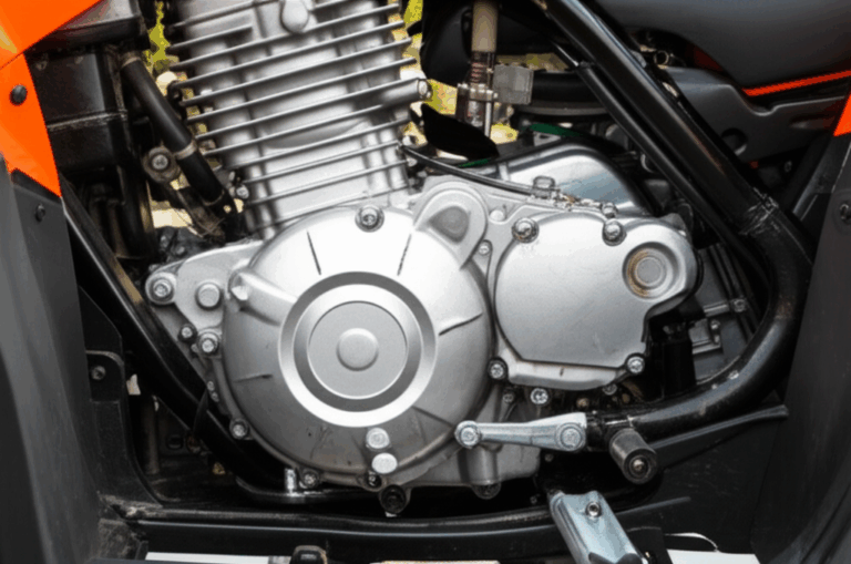
Here is the short version. The stator generates AC. The rectifier converts that AC to DC and regulates system voltage for the battery and loads. If the stator runs hot, shorts a winding, opens a phase, or leaks to ground, the rectifier has to process current and voltage that no longer match its design envelope. That creates excess heat. Heat cooks diodes or MOSFETs. Heat fatigues solder joints. Heat degrades potting. Heat is the silent killer in electronics.
In the field this looks like repeated charging system problems. Mechanics see stator failure symptoms and rectifier regulator damage arrive together. You see melted connectors, ripple voltage, dimming lights, engine cutting out electrical under load, or a battery that dies overnight. The root cause can be in the magnetic core. It can live in the copper and steel. It can hide in the coatings and assembly. It can show up in how the rectifier is mounted or cooled. You need a plan that covers both the electrical system diagnosis and the upstream design choices that set reliability.
Engineering Fundamentals: Charging System Basics and Why Laminations Matter
Let’s map the system in clear terms.
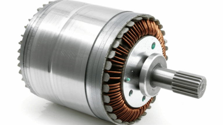
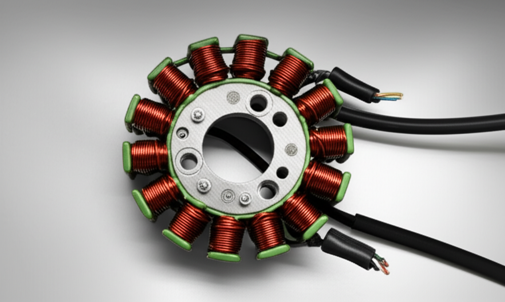
- The stator is a set of coils wound around a laminated iron core. A permanent-magnet rotor spins around it. That motion cuts magnetic flux through the coils and produces AC voltage. More engine RPM equals more voltage and current up to thermal limits.
- The rectifier-regulator (often a single unit) uses diodes or MOSFETs to rectify AC to DC. Then it clamps output to a proper charging voltage at the battery. Most 12 V systems target roughly 13.8 to 14.8 V during normal operation. Your repair manual provides the exact spec.
- The battery smooths ripple and supplies current when loads spike. It stabilizes system voltage for the ECU, ignition system, lights, and accessories.
Why do stator laminations matter? Eddy current loss. Hysteresis loss. Heating. Imagine eddy currents like tiny whirlpools in a river. A changing magnetic field induces currents in the iron core itself. Those currents generate heat and waste power. Thin, insulated laminations break up those whirlpools. Less loss. Cooler operation. Lower temperature rise in the windings. Better stator output voltage at a given RPM. Less electrical stress on the rectifier.
- Hysteresis loss depends on the material’s B-H curve and coercivity. Think of coercivity as the material’s resistance to changing its magnetic state. Lower coercivity reduces hysteresis loss for the same flux swing.
- Eddy current loss grows with lamination thickness and the square of frequency. Thinner laminations cut this loss. So does a high-quality insulation coating between sheets.
That’s why the choice of electrical steel laminations matters for the stator core. Better laminations lower core loss. Lower loss equals lower heat. Lower heat protects the winding insulation and the rectifier downstream.
How a Bad Stator Damages the Rectifier
Failures rarely happen in a vacuum. Most are a chain. Here is the chain that links a failing stator to rectifier damage.
- Overheating due to excessive or irregular current
- Shorted stator windings drive high current through the rectifier. The rectifier’s heat sink tries to keep up. The internal diodes or MOSFETs run hot. Thermal stress cracks them over time. The rectifier gets hot to the touch fast and stays hot at idle.
- Open circuit stator windings knock out one phase in a three-phase stator output. The rectifier must work with poor input. That means higher ripple and uneven loading of remaining phases. The regulator section chases a stable DC current and voltage. Heat rises again.
- Burnt stator windings or degraded insulation lead to inter-turn shorts. That drops coil resistance and raises current. The rectifier sees excessive current and dies young.
- Voltage spikes and fluctuations
- Inconsistent stator output creates irregular AC. The rectifier’s solid-state components see voltage spikes or dips. MOSFET rectifier regulator designs handle a lot. They do not like out-of-bounds transients.
- Lack of regulation margin. The regulator can clamp overvoltage within design limits. A bad stator can push it beyond safe operation. Overvoltage and excessive current hit the rectifier together. Damage follows.
- Prolonged stress and overwork
- The rectifier processes heat for breakfast. It cannot digest lunch and dinner as well. If the stator runs weak or erratic for weeks, the rectifier works overtime. Thermal cycles fatigue everything inside. You often see new rectifier burned out soon after a stator failure that went undiagnosed.
- Heat dissipation issues get worse when mounting lacks airflow or thermal paste. A rectifier running at its thermal cliff will not last long when a stator goes off-spec.
These mechanisms match what mechanics report every day. A weak stator output leads to rectifier output too low. The battery not charging masks the real problem for a while. Then the regulator overcompensates and runs hot. Sometimes you see the reverse. A rectifier output too high overcharges the battery. That can cook electrolyte. It also points to a regulator that is already damaged. So you test both.
Symptoms You’ll See in the Field
Charging system symptoms overlap. Use this list to separate signals from noise.
- Battery-related issues
- Dead battery. Battery not holding a charge after rides or runs. Parasitic draw charging system checks show normal draw. You still find undercharging on the road.
- Overcharging is less common from a stator alone. It happens if the rectifier fails in a way that lets voltage climb. Watch for swelling and cooked smell from the battery.
- Dimming headlights or dashboard lights at idle or under load. Headlight dimming charging issues often point to low DC output from the rectifier or weak AC from the stator.
- Engine performance problems
- Engine cutting out electrical at low RPM when the charging system cannot support ignition and ECU loads.
- Misfires at steady throttle if voltage dips. Poor throttle response when DC voltage sags.
- Difficulty starting due to low battery and weak DC supply.
- Visible and audible cues
- Burning smell from stator or rectifier. Melted wires or connectors near the rectifier due to resistive heating and excessive current.
- An excessively hot rectifier. They run warm. They should not be too hot to touch within seconds after short idling.
- Gauge flicker charging problem. Voltage readouts on bikes with displays will flutter when ripple voltage rises.
- Charging system context
- Motorcycle no charge scenarios show up after accessories get added. High current draw stator conditions can appear if the machine runs extra lighting or heated gear without margin.
- Marine engine rectifier problems get worse with poor cooling airflow. ATV stator issues often track with mud, water, and heat cycles. Snowmobile charging systems live in cold air but deal with thermal shock and vibration.
From a brand angle, none of the big names are immune. Honda, Yamaha, Kawasaki, Suzuki, and Harley-Davidson all use permanent magnet stator systems on many models. Automotive alternator vs stator rectifier designs differ because automotive alternators use wound rotors with field control. Different failure modes. Similar physics. The principle stands. Excess heat and erratic input destroy rectifiers.
Diagnosis: Separate Stator vs Rectifier Faults
You need a multimeter and the repair manual. The manual provides test points, proper charging voltage, torque specs, and safety notes. You bring a clear method.
- Essential tools and setup
- Multimeter with AC and DC voltage modes and a diode test. Good test leads and clips. A safe test stand or clear access to connectors.
- The motorcycle wiring harness diagram or charging system schematic. Follow the path from stator to rectifier to battery. Note connector pins and grounds.
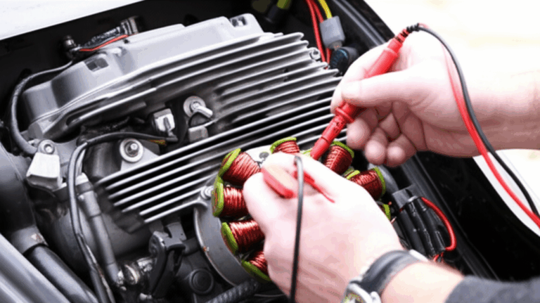
- Stator testing
- AC voltage output test. Unplug the stator from the rectifier. Start the engine and measure AC current from stator indirectly through AC voltage between phases. For a three phase stator test, check all three pair combinations. Voltage should rise with RPM smoothly. The repair manual lists nominal ranges. Big imbalances point to a shorted stator coil or open circuit stator.
- Resistance test. With engine off and stator unplugged, measure resistance between each pair of phases. They should match closely. A stator resistance too low suggests inter-turn shorts. A stator resistance too high suggests a poor connection or partially open winding.
- Ground fault test. Check each phase to engine ground. You should read open circuit in most permanent magnet stator systems. Any continuity points to a ground fault stator. That can cook the rectifier fast.
- Rectifier testing
- DC output test. With the rectifier connected, measure DC voltage at the battery at idle and through the RPM range. You want a stable charging voltage within spec under load. Use lights and fans to add load. A rectifier output too low or too high signals trouble.
- Diode test. Many service manuals document how to test the diode bridge rectifier using the multimeter’s diode mode. Reverse conduction indicates diode failure. MOSFET rectifier regulator designs add complexity. You still can perform a basic sanity check.
- Visual inspection. Look for heat discoloration, cracked potting, melted connectors, or signs of silicone rectifier damage from previous overheating.
- Why proper diagnosis matters
- Avoid replacing the wrong part. Avoid installing a new rectifier on a shorted stator. That is the fastest way to get a new rectifier burned out. Replace both only when tests say both are bad. Otherwise you waste time and money.
When in doubt, measure ripple voltage at the battery. Excessive ripple means poor rectification or a missing phase. That narrows the search quickly.
Material and Design Choices That Reduce Failures
You can treat symptoms forever. Better to address root causes during design and sourcing. The stator core, windings, insulation system, and the rectifier’s thermal design all shape system reliability. Here is a practical guide to the choices that matter.
Material considerations
- Silicon steels (non-oriented grades)
- Good general-purpose choice for rotating machinery across motorcycles, ATVs, UTVs, and many industrial motors. Solid balance of cost and magnetic performance at typical charging frequencies tied to engine RPM. Lower core losses than plain carbon steels. Consistent performance in permanent magnet stator systems.
- Watch lamination thickness and insulation quality. Thinner sheets reduce eddy current loss. High-quality coatings cut interlaminar shorts.
- Cobalt-based alloys
- Outstanding saturation flux density and high-frequency performance. You pay for it. Consider cobalt for aerospace or compact high-power-density alternator designs where weight and size are critical. Use it when budget supports the premium.
- Grain-oriented silicon steel (CRGO) vs non-oriented (CRNGO)
- CRGO shines in transformers where flux runs primarily in one direction. CRNGO suits rotating magnetic fields and is the standard for traction and alternator stators. Use CRGO for transformer lamination core designs. Use CRNGO for rotating machines.
- Insulation coatings
- Choose coatings with the right thermal class and chemical resistance. The coating must survive varnish bake cycles, oil mist, and heat. Poor coatings lead to stator winding insulation breakdown and interlaminar shorts. That pushes current higher and heats the rectifier.
For a broad overview of core material families and trade-offs, see these resources:
- A primer on motor core laminations
- The role of high-grade stator core lamination
Lamination thickness and core loss
- Thinner is cooler. Eddy current loss scales with thickness and frequency. You lower loss by using thinner laminations. That cuts stator heat at high RPM. The rectifier sees steadier AC input and runs cooler.
- Watch the cost curve. Thinner gauges raise cost and may require tighter die control. Your design window should weigh performance vs stamping complexity.
Stack design and rotor interaction
- Flux path symmetry matters. Unbalanced flux raises vibration and local heating. It also injects ripple into the rectifier.
- Rotor magnet grade, geometry, and air gap control your flux density. Aim for a clean sinusoidal induced voltage. Trapezoidal waveforms raise harmonic content and ripple voltage. That stresses the rectifier-regulator. A well-matched rotor core lamination and magnet set reduces harmonics.
- BLDC and PMAC differences. A [bldc stator core] can be optimized for trapezoidal back EMF and Hall-based commutation. PMAC targets sinusoidal back EMF. Either way, lower core loss equals cooler electronics.
Winding, slot fill, and resistance
- Copper fill factor is a balancing act. More copper reduces resistance and improves output at low RPM. Too much fill makes winding and impregnation hard. It can trap heat. It can also raise leakage inductance depending on geometry.
- Use Ohm’s Law as your sanity check. For a given load current, voltage drop across winding resistance becomes heat. Keep resistance and I^2R loss under control.
Impregnation and bonding
- Varnish impregnation supports heat transfer from copper to laminations and on to the housing. Good impregnation stabilizes windings against vibration. Poor impregnation lets wires rub and break insulation over time. That shows up later as shorted stator windings, weak stator output, and intermittent charging issues.
- Bonded stacks vs interlocking vs welding
- Interlocking laminations work like LEGO bricks. They build a strong stack without heavy welding that can degrade magnetic properties near the weld.
- Adhesive bonding offers excellent damping and tight stack factor. It can reduce audible buzz. It adds process steps.
- Welding is simple and strong. It introduces localized heat-affected zones. Use it carefully. Anneal when required to restore magnetic performance.
Manufacturing process choices
- Progressive die stamping
- Best for high volumes. Great repeatability. Low burr when dies are sharp and maintained. Burr height control matters because burrs puncture insulation and cause interlaminar shorts.
- Laser cutting
- Ideal for prototypes and low-volume parts. You get freedom for complex geometries. Heat-affected zones can increase loss locally. Post-cut stress relief and coating touch-up help.
- Fine blanking and wire EDM
- Niche processes for exceptional edge quality. Use when performance demands justify the cost.
Rectifier design and mounting
- Heat sink and airflow
- A rectifier bolted to a subframe with thermal paste and a clean path to airflow will live longer. Avoid pockets that trap hot air. Avoid locations near exhaust heat.
- Component choice
- Diode rectifiers are robust. MOSFET rectifier regulator designs offer improved regulation and lower internal dissipation. MOSFETs still face thermal limits and voltage spikes. Give them margin.
- Grounding and connectors
- Damaged rectifier from poor ground is common. A bad ground charging system raises heat and ripple. Use solid grounds and sealed connectors. Corrosion is a silent killer.
Process Controls and Preventive Maintenance
You can design the best system on paper. Manufacturing and maintenance will still decide the real lifespan.
- Process controls
- Verify lamination insulation integrity after stamping. Measure stack factor. Inspect burr height. Track anneal cycles and coating cure.
- Control varnish viscosity and bake profiles. Check penetration and void content on cut sections.
- Validate winding resistance and inductance per lot. Compare against SPC limits. Small drifts signal insulation damage or copper diameter changes.
- Preventive maintenance in the field
- Regular battery checks. A weak battery can overwork the charging system. The regulator runs hotter when it has to push more current for longer.
- Inspect wiring harness and connectors for corrosion or looseness. Check for heat discoloration near the rectifier and stator leads.
- Ensure adequate airflow to the rectifier for cooling. Clean debris. Reroute heat shields if needed.
- Address charging system warnings promptly. Intermittent charging issues now become failed charging system components later.
Application Fit: Motorcycle, ATV, Marine, EV, and More
Different vehicles push different stressors onto the charging system. Tailor lamination and rectifier choices to the use case.
- Motorcycles and ATVs
- Permanent magnet stator systems dominate. They generate AC current from stator at all RPMs. The rectifier bleeds excess as heat at high RPM if the system uses a shunt regulator. Better laminations lower stator heating. MOSFET regulators cut rectifier dissipation compared to SCR shunt types.
- Dirt and water intrusion challenge connectors. Vibration challenges winding stability. Choose coatings and impregnation with that in mind. Many forum threads show stator and rectifier failing together on Honda, Yamaha, Kawasaki, Suzuki, and Harley-Davidson models. The physics is the same across brands.
- Marine engines
- Cooling airflow can be limited. Salt and humidity add corrosion risk. Use sealed connectors and robust grounds. Heat dissipation rectifier strategy matters a lot. A cooler stator helps keep the rectifier cooler.
- Snowmobiles
- Thermal shock dominates. Cold starts. Rapid warm-up. Use insulation systems with matching thermal expansion. Varnish that stays flexible at low temperature helps.
- Automotive alternators
- Alternator designs use wound rotor field control. The regulator adjusts field current to control output. A failing stator still increases rectifier diode heat. The same causes of rectifier failure show up. Overheating, diode breakdown, and voltage regulation issues still apply.
- Industrial and EV traction motors
- Higher frequency content from switching inverters changes the loss picture. For PMAC stators, use thinner laminations and tailored coatings. Keep an eye on ripple current and voltage spikes from the inverter that can interact with auxiliary rectifiers or DC/DC converters on-board.
Procurement and Cost Considerations
Engineers and procurement must meet budget while protecting reliability. A few practical tips.
- Specify what matters most
- Lamination grade, thickness, coating class, burr limits, flatness, and anneal requirements. Put these in the drawing and the PO. Vague specs lead to high variation.
- Ask for process capability
- Request SPC data on thickness, burr height, and coating resistance. Ask for sample stacks with measured stack factor.
- Consider the total system
- A slightly more expensive lamination stack that reduces core loss can save you rectifiers under warranty. The ROI often looks better when you include labor, returns, and brand impact.
- Choose trustworthy partners
- If you need a high-level overview of available stacks and materials, start with a general guide to core lamination stacks. You will find examples across industries and formats.
Quick Reference: Common Faults and Their Clues
You will run into the same patterns again and again. Keep this mini checklist handy.
- stator failure symptoms
- Low or no AC output. Imbalanced phases. Rising heat at idle. Burnt smell near the engine cover. Discolored windings.
- voltage regulator failure signs
- Erratic charging voltage. Overvoltage at high RPM. Undercharging with load. Excessive case temperature quickly after startup.
- rectifier diode failure
- High ripple voltage. Battery drains when parked. Heat at connector. Melted plastic at plugs.
- ground fault stator
- Blown fuses. Shocks or tingles near case. AC voltage readings changed when measuring to ground rather than between phases.
- ripple voltage charging system
- Flicker in lights and gauges. Electrical noise into ECU or radios. Unstable idle AFR due to ECU seeing noisy power.
Tie these clues back to the physics. Excess heat leads to insulation breakdown. Shorts drive excessive current. Voltage spikes hit component breakdown limits. Those three kill rectifiers.
Safety and Testing Notes You Should Not Skip
- Always unplug the stator to test AC output. Testing through the rectifier can mask failures.
- Use proper meter settings. AC for stator output. DC for battery voltage. Diode mode for rectifier checks. Bad meter setup yields nonsense.
- Keep fingers clear of rotating parts. Measure with clip leads when possible. Wear eye protection. Hot connectors and spinning rotors are no joke.
- Follow the repair manual. OEM specs differ by model. Shindengen MOSFET regulators on sportbikes have different test steps than some older SCR units.
Frequently Asked Design Questions
- Can a faulty stator ruin a battery
- Yes when a bad stator causes chronic undercharging. The battery sulfates and loses capacity. Overcharging usually points to the rectifier-regulator.
- Why does my rectifier keep failing
- Heat usually. Check airflow. Check grounds. Verify the stator for shorts or imbalanced phases. Confirm the battery is healthy. A weak battery increases rectifier duty cycle.
- Is a MOSFET rectifier worth it
- Often yes. They regulate better under varying loads and reduce internal heat. They still need clean stator input and good cooling.
- Should I replace both stator and rectifier
- Test first. Replace both only when both fail checks or when field experience for your platform shows paired failures are common and you need to reduce repeat labor.
Engineering Takeaway and Next Steps
Here is the distilled list you can act on today.
- A bad stator can and often will damage a rectifier. The mechanism is excess heat driven by high current, spikes, and ripple.
- The stator core’s lamination material, thickness, insulation coating, and manufacturing quality set the baseline for heat and reliability.
- Testing is simple. Unplug and measure stator AC, resistance, and ground faults. Check rectifier DC output and diode behavior. Inspect connectors and grounds.
- Preventive steps work. Maintain batteries, clean connectors, and ensure airflow to the rectifier. Address early signs like dimming lights and gauge flicker.
- Good design choices up front save money. Match lamination grade and thickness to your frequency range. Control burrs and coatings. Choose robust rectifiers with proper cooling.
- Align design and procurement. Specify what matters. Ask for process data. Balance cost against field reliability and warranty risk.
If you are refreshing a platform or sourcing a new alternator-stator assembly, start with the stator core. Better laminations cut losses and temperature. That reduces electrical stress on the rectifier. For a deeper material and process overview, review motor core laminations and specific stator core lamination options. If your design work includes rotor optimization, look at the interplay with rotor core lamination. You will make faster progress when you consider the full magnetic circuit.
Final tip. Keep the mantra close. Clarity over complexity. Diagnose with a meter. Design with physics. Specify with care. Your charging system will thank you with stable voltage, cooler components, and fewer returns.
Notes on terminology and standards you may encounter:
- Diodes and MOSFETs are solid-state devices that control current direction and regulate voltage. They have breakdown limits that spikes can exceed.
- Ohm’s Law links voltage, current, and resistance. It is enough to estimate heat in windings and rectifiers with I^2R.
- ASTM and IEC specifications govern sheet steel grades and coatings. IEEE publications discuss core loss, permeability, and lamination effects. Use these references to align material data with your performance targets.
By taking a system view and tightening your material and process choices, you turn a frustrating “why did my rectifier melt” failure into a design you can trust over the full lifecycle.