Can a Bad Stator Cause Weak Spark? (Yes, Here’s How to Diagnose It)
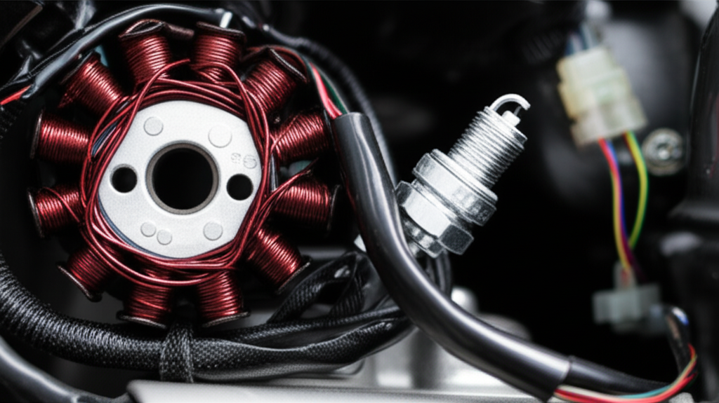
If you’re chasing a weak spark, start at the stator. In many motorcycles, ATVs, outboard motors, and small engines, the stator feeds the ignition module and charges the battery. When it falters, spark energy drops. Misfires follow. The short answer to your question is yes. A bad stator can absolutely cause weak spark. This article explains why, how to prove it with real measurements, and what to do next. We’ll also connect the dots to material and manufacturing choices, because how you design and build the stator core laminations sets the floor for long-term reliability.
We’ll take a practical, engineering-first approach. Clear steps. No fluff. Straight to the point so you can diagnose, decide, and move on with confidence.
In This Article
- Why Weak Spark Often Starts at the Stator
- The Engineering Fundamentals: How a Stator Makes Spark Possible
- Symptoms That Point to the Stator
- Step-by-Step Diagnosis With Real Numbers
- Differential Diagnosis: When It Isn’t the Stator
- Material and Manufacturing Choices That Influence Stator Reliability
- Which Approach Fits Your Application
- Cost, Repair, and Procurement Notes
- Engineering Takeaways and Next Steps
Why Weak Spark Often Starts at the Stator
Problem first. You see a yellowish spark instead of a crisp blue one. The engine hard-starts or stumbles. Maybe it idles rough or dies when hot. Many techs jump straight to coils and plugs. That makes sense. Yet the stator sits upstream and it sets the stage for strong ignition.
Here’s the core idea. The stator and flywheel (magneto) generate AC voltage. Your CDI unit or ignition module uses that voltage to charge a capacitor or a coil. The ignition coil then steps that energy up to tens of thousands of volts at the spark plug. If the stator output sags because of damaged windings, an internal short circuit, or corrosion at connectors, the ignition never gets full charge. The coil’s magnetic field weakens. The spark turns thin and yellow. Combustion suffers.
You asked whether a bad stator causes weak spark. It does. Now let’s unpack the “why” and the “how” with just enough physics to keep you grounded.
The Engineering Fundamentals: How a Stator Makes Spark Possible
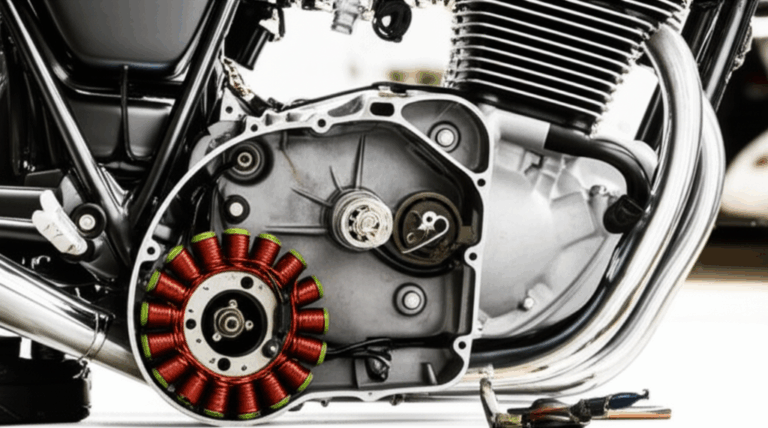
Think of the stator as a fixed set of copper windings wrapped around an iron core. The flywheel carries permanent magnets. As the flywheel spins past the stator, it sweeps a changing magnetic field through the windings. Faraday’s law goes to work. Changing flux induces voltage. That AC feeds two key subsystems:
- The ignition system: CDI or inductive ignition needs a healthy AC feed or a trigger from a pickup coil.
- The charging system: a regulator rectifier converts AC to DC to charge the battery and power loads.
A couple of simple but crucial concepts explain why weak spark shows up when the stator degrades.
- Flux and magnetic circuit: High magnetic permeability in the stator core lets flux flow easily, much like water through a wide pipe. Laminations break up eddy currents that would otherwise waste energy as heat. Better laminations mean lower core losses and more stable voltage under load.
- Eddy currents and hysteresis: Eddy currents are like little whirlpools inside the steel. Thinner, insulated laminations act like rocks in the river that break up big whirlpools into small ones. Hysteresis loss depends on the material’s coercivity, which is its resistance to demagnetization, and it scales with frequency and peak flux. Both losses convert energy into heat that doesn’t help your spark.
- Winding resistance and shorts: Stator windings age. Heat breaks down insulation. Oil contamination accelerates it in wet-stator designs. A shorted turn or a partial short to ground drops output voltage. An open circuit kills a phase entirely.
- System dependence: On many motorcycle and ATV systems, the CDI charges from a dedicated source coil on the stator. Low stator voltage means the CDI capacitor never charges fully. The ignition coil receives a weaker pulse, so the spark weakens. In battery-fed inductive systems, poor charging drags system voltage down, which can still cause weak spark under cranking or at low RPM.
That’s the big picture. Now let’s talk about how faults in the stator translate to spark behavior you can see.
How a Faulty Stator Leads to Weak Spark: The Electrical Path
- Insufficient voltage output: Damaged windings, an internal short circuit, or an open circuit within a stator coil reduces AC voltage. Lower voltage means the CDI unit cannot fully charge its capacitor, and the ignition coil never stores enough energy. You get weak spark, misfires, and backfires.
- Impact on the CDI unit: The CDI wants a certain voltage window to charge quickly between sparks. When output drops, the CDI pulse shrinks. That smaller pulse leads to poorer ignition coil primary current and less magnetic field strength. Result: yellow spark instead of bright blue or white.
- Direct stator-to-coil systems: Some small engines drive ignition coils directly off the magneto. Low stator flux or shorted windings give you weak primary current. If it looks anemic at the plug, look upstream.
- Intermittent failures: Partial shorts or corroded connectors cause voltage to come and go. The engine runs fine at times then coughs or dies. Heat can open a fault as the winding expands. Vibration can make a broken strand touch and release. You see intermittent misfires or weak spark under load or at specific RPM ranges.
You can spot these failures by measuring real outputs, not by guessing. We’ll get to that.
Symptoms That Point to the Stator
Weak spark is the headline. Other signs help you narrow it down faster.
Engine performance issues:
- Hard starting or no start condition
- Misfires and rough idle
- Stalling at idle or while cruising
- Poor acceleration with flat throttle response
- Backfiring on decel or under load
- High RPM weak spark that shows up only near redline
- Low RPM weak spark that shows up during cold starts
Charging system problems:
- Battery not charging or battery that constantly drains
- Dim headlights or flickering dash lights
- Accessories that brown out at idle
- Regulator rectifier overheating when the system tries to compensate
Other observable signs:
- Burning smell from overheated windings
- Oil contaminated stator in wet sump designs
- Discolored, burnt, or cracked stator windings on visual inspection
- Corroded stator connectors and green crust on pins
- Dying while running with no warning
Pattern-based hints:
- Weak spark on one cylinder suggests a per-cylinder coil or lead, yet multi-phase stator failures can mimic this if one phase feeds a subcircuit.
- Intermittent weak spark that correlates with heat points to insulation breakdown or a pickup coil issue.
- Weak spark at high revs can indicate insufficient stator output frequency response, an ignition coil saturation limit, or CDI charge time constraints.
You now have symptoms on paper. Time to prove the cause.
Step-by-Step Diagnosis With Real Numbers
You need a multimeter. An inductive timing light or an adjustable spark tester helps. If you have an oscilloscope, even better. Always consult the service manual for your specific engine. Values vary by model and by year.
Safety first:
- Disconnect the battery when checking resistance.
- Secure the vehicle to avoid accidental starts.
- Keep metal tools clear of the flywheel magnets.
1) Visual inspection
- Look for frayed wires, pinched harnesses, and oil-soaked stators.
- Check the wiring harness and ground wire terminations. Clean, tight, and corrosion free is the standard.
- Verify the pickup coil gap and alignment with the flywheel trigger. A damaged pickup coil can cause weak or no spark.
2) Resistance (ohms) test
- Use an ohm meter or multimeter set to the lowest range that fits. Measure between stator output wires according to the stator wiring diagram.
- Compare to the service manual’s stator resistance chart or specs. Open circuit means infinite resistance. That indicates a break. Substantially lower than spec often means a short between turns. Higher than spec can indicate corrosion or partial opens.
- Check each stator coil to engine ground. You should see no continuity in most designs. Continuity often means a short to ground.
3) Continuity and ground short test
- With the meter on continuity, check from each stator lead to the stator core. You should not hear a beep. A beep signals a stator ground fault or insulation breakdown.
4) AC voltage output test
- Reconnect the stator, start the engine, then measure AC voltage across stator leads with the stator disconnected from the regulator rectifier. This isolates the stator.
- Typical outputs vary widely. For many multi-phase stators you might see 20 to 70 VAC per phase at idle that climbs with RPM. Some single-coil ignition source windings for CDI can produce hundreds of volts AC unloaded at higher RPM. Always check the service manual for stator output voltage specifications.
- Low readings indicate stator output insufficient for reliable spark and charging.
5) Pickup coil and crankshaft position sensor checks
- Measure pickup coil resistance to spec and verify output AC voltage during cranking. Pickup coil weak signals can produce weak spark timing or misfires.
- Many engines call this part the pulse generator. Others use a crankshaft position sensor that feeds an ECU. Low amplitude or noisy signals can cause weak or erratic spark.
6) Inductive coil checks
- For an ignition coil, measure primary and secondary resistance. Compare to the manual. Out-of-range values suggest a failing coil that can mimic stator failure.
- Use an inductive pickup coil test with a timing light or a current clamp to confirm primary current ramp.
7) Battery and charging checks
- Measure DC voltage at the battery with the engine running. A healthy system shows an increase over static battery voltage. If it stays low, suspect stator or regulator rectifier.
- Perform a voltage drop test from grounds to confirm the ground network integrity. Bad grounds cause weak or no spark.
8) Oscilloscope insight when available
- Check the stator AC waveform. Flattened peaks or asymmetric waveforms can reveal internal stator short circuits.
- Look at the CDI primary pulse and ignition coil primary current. A shrunken pulse points upstream to poor stator or CDI behavior.
9) Spark quality check
- Use a spark tester with an adjustable gap. A strong system jumps a larger gap with a blue arc. A weak system barely crosses a small gap and glows yellow or orange. This gives you a repeatable baseline.
10) Cross-check with heat and RPM
- Run the engine to operating temperature. Repeat key tests. Some failures only show up hot. Test at idle and at a mid RPM. Intermittent weak spark often tracks with temperature and speed.
If the stator fails resistance or AC output tests, you found your culprit. If it passes, keep reading.
Differential Diagnosis: When It Isn’t the Stator
Weak spark has many causes. Don’t swap parts until you rule out these common issues.
- Faulty ignition coil: A weak or shorted ignition coil won’t store energy. Check primary and secondary resistance. Use a scope or a current clamp if you can. A coil that saturates poorly gives a weak spark.
- Malfunctioning CDI unit: CDI boxes fail with age and heat. Many lack easy bench tests. Substitution with a known good unit may be the only definitive move. A failed CDI can deliver a CDI box weak spark symptom that mimics a stator issue.
- Damaged spark plug or wire: Inspect plug tips. Gap to spec with a feeler gauge. Replace if fouled or cracked. Measure plug wire resistance. High resistance creates weak spark.
- Weak or failing battery: Even CDI systems rely on a healthy electrical environment for sensors and relays. Inductive systems rely heavily on battery health. A weak battery can cause weak spark during cranking.
- Bad regulator rectifier: The R/R mainly affects charging. Yet a failing unit can overload or cook the stator over time. It can also introduce electrical instability that leads to intermittent misfires and weak spark.
- Poor grounds: Corroded or loose grounds break circuits and introduce voltage drops. Clean and torque them. A bad ground can cause weak spark, dead modules, and ghost codes.
- Pickup coil or crankshaft position sensor faults: Bad triggers cause timing drift and misfires. Poor timing can look like weak spark when the real problem is late or inconsistent spark.
- Air-fuel side issues: A clogged jet or injector can make the engine feel flat. Weak spark often makes a rich condition because unburned fuel increases HC and CO. Some users ask if a bad stator can cause a lean condition. Weak spark doesn’t create a lean mixture. It causes incomplete combustion that oxygen sensors can misread which may push the ECU to add fuel.
You want a clean bill of health on these items, or a clear match to your stator test results, before you buy parts.
Material and Manufacturing Choices That Influence Stator Reliability
Now we put on the design and procurement hat. Why do stators fail in the field and what can you do up front to minimize that risk? Laminations and winding quality sit at the center of the stator’s life expectancy. You can move the needle through material selection, lamination thickness, manufacturing process, insulation systems, and thermal management.
Core lamination materials and thickness
- Electrical steel laminations: Choose high-quality nonoriented electrical steel with appropriate grade and thickness for your operating frequency. Thinner laminations reduce eddy current loss at higher frequency which keeps temperature under control and preserves winding insulation.
- Silicon steel laminations: Silicon increases resistivity and reduces core loss. Classic motor grades balance cost and performance. Thicknesses like 0.35 mm or 0.50 mm serve many low frequency machines. High frequency applications may push thinner.
- Cobalt alloys: You get higher saturation flux density and lower loss at elevated frequency. Cost rises sharply. Use them when power density or temperature margins demand it.
- Standards and datasheets: Consult material standards such as ASTM A677 or ASTM A683 for nonoriented silicon steel. For motors and generators, IEC 60034 provides relevant performance test frameworks. These references help you set defensible specs.
Core stack construction
- Stamping vs laser cutting vs wire EDM: Stamping excels in volume with low unit cost once you amortize tooling. Laser cutting supports rapid iteration and complex features with minimal tooling cost which suits prototyping and low volume builds. Wire EDM brings precision at higher cost for specialty geometries. Laser and EDM can create heat-affected zones that may increase loss if you skip post-process stress relief. Stamping requires quality die maintenance to avoid burrs that raise interlaminar shorts.
- Interlocking vs welding vs bonding: Interlocking laminations work like LEGO bricks. They hold a tight stack without heavy heat input. Welding adds rigid strength but can locally degrade magnetic properties if you apply too much heat. Modern bonding methods with thin adhesives can reduce vibration noise, improve stack integrity, and keep loss low.
- Coating and insulation: The interlaminar coating resists shorting between plates. Good coating equals lower eddy currents and more predictable heat behavior. Choose coatings that tolerate your operating oil and temperature environment.
Winding and insulation system
- Copper quality and fill: Higher slot fill improves performance, yet it must not damage enamel. Tight corners and sharp edges can nick insulation which invites internal short circuits later.
- Slot liners and impregnation: Use proper slot liners and vacuum pressure impregnation where appropriate. A robust insulation system resists heat and oil which slows aging stator failure and prevents internal stator short conditions.
- Thermal path design: Ensure oil flow or airflow paths keep windings and core at safe temperatures. Excess heat degrades enamel and raises resistance which reduces output. Good thermal design fights overheating stator damage.
Manufacturing controls and diagnostics
- Incoming material verification: Verify thickness, coating class, and magnetic properties of electrical steel. Material mix-ups happen. Good QA catches them.
- Stator testing tool suite: Add resistance tests, surge tests, hipot to ground, and partial discharge checks as needed for your product class. These tests catch insulation breakdown before the unit leaves the line.
- Process control on stack height and pressure: Stack compression affects magnetic path and mechanical stability. Keep it consistent. Poor stack control shows up as variable flux and noise.
- Connector and harness quality: Corroded stator connectors in the field often trace to poor plating or sealing. Invest in better terminals and boots. It pays off in reliability.
Design-for-service
- Shield the pickup coil from debris. Tighten tolerance on air gap and mount stiffness.
- Specify robust grommets and strain reliefs. Vibration breaks wires if you ignore cable dynamics.
- Provide clear test points for stator output voltage test and continuity test. Field techs need easy access.
If you want a deeper dive into how core design choices drive reliability and performance, see these resources:
- How the quality of the stator core lamination influences flux uniformity and heat
- A broad overview of motor core laminations for different machine topologies
- Material tradeoffs in electrical steel laminations for motors and generators
- Complementary considerations for rotor core lamination geometry and losses
Which Approach Fits Your Application
You need a solution that matches your use case. One size never fits all. Use this map to pick a path that aligns to performance, cost, and production volume.
Application focus: small engines, powersports, and outboards
- Priorities: ruggedness, thermal endurance, oil compatibility, serviceability.
- Material choice: mid-grade nonoriented silicon steel with stable coating. Thickness tuned to your stator output frequency. Many magneto systems run at relatively low electrical frequency tied to engine RPM and pole count which eases core loss constraints.
- Manufacturing: stamping for volume. Laser for quick design turns. Interlocking stacks for low heat input with tight assembly. Bonding when noise and rigidity matter.
High power density EV traction or high-frequency BLDC
- Priorities: low core loss at higher electrical frequency, minimal torque ripple, high slot fill.
- Material choice: premium nonoriented steel or cobalt alloys in thinner gauges. The bldc stator may also push for skewed slots to cut cogging torque.
- Manufacturing: precision stamping with excellent burr control or laser with post-cut relief. Bonded stacks for stiffness and NVH control.
Harsh environment industrial machinery
- Priorities: thermal robustness, contamination resistance, long service life.
- Material choice: conservative lamination thickness with coatings that handle moisture and oil. Slot liners with high thermal class.
- Manufacturing: stamping with tight die maintenance. Generous creepage and clearance at terminations.
Low-volume prototypes and R&D
- Laser cutting shines for rapid iteration. You avoid tooling lead time.
- Expect slightly higher core losses unless you manage edge effects. Heat treat or stress relief can help.
Honest constraints:
- Laser cutting offers fantastic flexibility and edge quality in small runs. For large production, stamping wins on cost and consistency.
- Bonding improves mechanical integrity and noise. It adds process steps and cost. Evaluate. Don’t assume.
- Thinner laminations cut core loss at higher frequency. They raise raw material cost and can challenge stamping dies and handling.
Cost, Repair, and Procurement Notes
When you confirm a bad stator, you have two choices. Replace it or rewind it.
Replacement
- OEM parts carry known fit and spec. Cost runs from about $50 for small engines to several hundred dollars for multi-phase motorcycle or ATV stators.
- Aftermarket parts range from excellent to questionable. Vet the supplier. Poor winding or weak insulation invites early failure. Cheap regulators can overheat and take a good stator with them.
- Replace the regulator rectifier if you see signs of overheating or voltage instability. A bad R/R can cook a new stator.
Rewind service
- Stator rewind service can save cost in low-volume or legacy applications. A skilled shop can match wire gauge, turns count, and insulation class. Ask for test documentation that includes resistance and hipot to ground.
Labor
- Accessibility dictates labor cost. Some stators sit behind a simple side cover. Others hide behind complex assemblies. Expect one to four hours of labor. Shop rates vary by region.
Procurement tips for new builds or redesigns
- Lock electrical specs and tolerances early. Winding turns, wire size, and core lamination geometry define output and heat.
- Insist on test data: resistance per coil, surge test results, hipot, AC output at defined RPM and load.
- Qualify the lamination stack: verify grade, thickness, coating, and stack height.
- Document the stator output frequency range and target AC voltage at key RPM points. Add an oscilloscope stator waveform capture to the PPAP or first article package if the application is critical.
Frequently Asked Engineering Questions About Weak Spark and Stators
How much voltage does a stator produce for ignition
- CDI source coils can produce from tens to hundreds of volts AC depending on design and RPM. Always check your service manual. Some systems charge a capacitor directly from the stator then dump it into the ignition coil.
What causes a stator to go bad
- Heat is the number one culprit. Electrical overload, poor oil quality, vibration, corrosion, and aging stator failure all play roles. Insulation breaks down which leads to internal stator short or an open circuit stator segment.
Can a weak battery cause weak spark
- Yes in battery-fed inductive ignitions. The coil never reaches full primary current when system voltage sags. You see weak spark, especially during cranking.
Can a bad ground cause weak spark
- Absolutely. The ignition coil and CDI need a solid ground path. Voltage drop at the ground wire steals energy from the spark.
Why is my spark yellowish instead of blue
- Yellow or orange spark often signals low energy. Root causes include stator voltage low, ignition coil weak, CDI issues, plug gap too wide, or high resistance in plug leads.
Blue vs yellow spark
- Blue or white suggests strong ionization and higher energy. Yellow suggests lower energy and slower rise time.
Can a bad stator cause a lean condition
- Not directly. Weak spark causes misfire and unburned oxygen in the exhaust which the O2 sensor can interpret as lean. The ECU may add fuel which creates a rich-running symptom.
Weak spark at high revs vs low revs
- High RPM weak spark often indicates inadequate CDI charge time or limited stator output at speed. Low RPM weak spark often points to low stator output at idle, high plug gap, or poor coil saturation.
Weak spark on one cylinder
- That often points to a per-cylinder coil, plug wire, or plug issue. A multi-output stator usually affects all cylinders unless the architecture routes distinct phases oddly.
What tools help
- A multimeter for ohm meter stator test and AC voltage test. A spark tester shows spark strength at a set gap. An oscilloscope reveals waveform anomalies. An inductive pickup coil test shows primary current behavior.
What about spec sheets and charts
- Use the service manual for stator resistance test values and stator resistance chart equivalents. Manufacturers publish stator output voltage specifications that fit the exact engine model.
When should I replace vs rewind
- If the stator shows physical damage or multiple coils test out of spec, replacement with a quality part is often faster. Rewind if the core and hardware are unique or expensive and a trusted shop can verify quality.
Putting It All Together: A Clear Troubleshooting Procedure
- Confirm the symptom: use a spark tester and observe color and gap distance. Blue spark good. Yellow spark suspect.
- Check the easy stuff: battery health, ground integrity, plug condition, plug gap setting for spark plugs, and obvious wiring issues.
- Measure stator resistance across coils. Compare to the manual. Look for open circuits or low resistance shorts. Check each wire to ground.
- Perform a stator voltage output test with the stator disconnected from the regulator rectifier. Measure AC at idle and at a set RPM. Compare to spec. Document.
- Verify pickup coil resistance and output. Ensure proper air gap to the flywheel trigger.
- Scope it if you can. Look at the stator output and the CDI primary pulse. Confirm the ignition coil primary current ramp.
- If stator numbers are low, replace or rewind the stator. Consider replacing the regulator rectifier if there are signs of overheating.
- Retest spark. Confirm that the system now jumps the intended gap with a strong blue arc.
This process catches 85 to 95 percent of stator-related weak spark complaints quickly. Intermittent issues sometimes need the extra step of heat soak testing or scope work.
Where Motor Laminations Meet Real-World Spark Reliability
For product designers and procurement teams, weak spark in the field traces back to choices you make months earlier. A few practical design levers help you reduce risk.
- Choose lamination grade with sufficient magnetic permeability to hit your target flux without overdriving the core. This keeps heating in check and preserves winding life.
- Set lamination thickness to control eddy current loss at your electrical frequency. Thinner laminations help at higher frequencies but raise cost and handling complexity. Balance is key.
- Specify robust interlaminar coatings that maintain insulation under oil, heat, and vibration.
- Control burrs tightly. Burrs create interlaminar shorts that raise loss and temperature. Good die maintenance or proper post-process finishing pays dividends.
- Engineer the winding insulation system for your thermal class and oil exposure. Thermal runaway crushes winding life.
- Test early and often. AC voltage test at defined RPM. Resistance baseline for all coils. Continuity to ground. Surge test on windings if the application warrants it.
Do this and you’ll see fewer stator failures that cause weak spark or no spark in the field. You also protect the regulator rectifier and the battery because the system runs cooler and more stable.
Your Engineering Takeaway
- Yes, a bad stator can cause weak spark. It starves the CDI or the ignition coil of energy.
- Diagnose with data. Use resistance tests, AC voltage tests, and if possible scope captures. Always compare to your service manual.
- Don’t overlook the simple culprits. Spark plugs, grounds, battery health, and ignition coils often fail too.
- Stator reliability starts with core design. Electrical steel quality, lamination thickness, stack construction, and winding insulation determine long-term performance.
- Match your manufacturing process to your volume and geometry. Stamping wins in volume. Laser or EDM shine for complex or low-volume parts.
- When you source stators or laminations, ask for real test data and material certs. Control burrs, coatings, and stack heights. Verify ground integrity and connector sealing.
Actionable next steps
- If you’re troubleshooting today: perform the resistance and AC voltage output tests. Use a spark tester to confirm spark energy. Replace or rewind the stator if it fails spec, then retest.
- If you’re designing for tomorrow: define lamination material, thickness, and coating that meet your frequency and thermal limits. Choose a stack assembly method that protects magnetic properties. Build a test plan that includes waveform and temperature checks.
- If you’re sourcing parts: request material certifications, process controls, and test reports on every batch. Verify that the supplier’s insulation system and coating hold up in your oil and temperature range.
Need a deeper technical discussion about stator cores, materials, or stack construction? Bring your application details, target RPM range, pole count, and performance requirements. A short engineering review can save months of trial and error and a pile of field returns.
Glossary and Fast Reference
- Stator: The stationary part of a generator or motor that houses windings.
- Magneto: A permanent magnet generator used to power ignition and accessories.
- CDI unit: Capacitor Discharge Ignition, an ignition module that stores energy in a capacitor then discharges it into the ignition coil.
- Regulator rectifier: Converts stator AC to DC and regulates voltage for charging and accessories.
- Eddy current loss: Energy lost as circulating currents in the core material due to changing magnetic fields.
- Hysteresis loss: Energy lost during each magnetization cycle due to the material’s magnetic properties.
- Coercivity: A material’s resistance to demagnetization.
- Continuity test: A check for a continuous electrical path. Used to find shorts to ground.
- Open circuit: A break in the electrical path that results in infinite resistance.
- Short circuit: An unintended low-resistance path that bypasses normal circuit routes.
Reference Notes and Standards
- For rotating electrical machines, IEC 60034 provides guidance on testing and performance definitions.
- For nonoriented electrical steel, see ASTM A677 and ASTM A683 for specification frameworks. Material datasheets from trusted mills will give loss curves, saturation flux density, and coating specifications.
- Service manuals from OEMs provide the authoritative stator resistance values, AC output ranges, and ignition system diagnostics for your specific model.
You now have a clear path. Test the stator. Confirm the cause. Fix it the right way. Then design and source laminations that make weak spark a rarity instead of a recurring headache.

